[Francis* et al., 4(4): April, 2017]
ISSN: 2349-5197
Impact Factor: 2.715
I
NTERNATIONAL
J
OURNAL
OF
R
ESEARCH
S
CIENCE
&
M
ANAGEMENT
MULTI PURPOSE AGRICULTURAL TRUCK
Albert Francis A
*1& Gowtham K
2*1&2
UG Students, Department of Mechanical Engineering, K.Ramakrishnan College Of Engineering,
Tiruchirappalli,Tamilnadu,India-621112
Keywords
:
agriculture truck,discharge valve,hydraulic piston,hydraulic stand,weight lifting rail trackAbstract
The design of carrier unit of the existing tippers must be modified to facilitate the collection of loads from the tippers into pockets or bags. The dropping of loads from a tipper can be done only at the rear side of the vehicle, it is to be modified to meet the requirements of dropping the loads on sides of the vehicle. While changing the direction of discharge from tippers the equilibrium of the vehicle must be considered to maintain the stability of the vehicle. So it requires special arrangements to maintain the equilibrium of the vehicle. Special vehicles are used to load heavy particles into the tippers, to increase the efficiency and to decrease the process cost a machine is to be attached with the vehicle to perform the loading operation..
Introduction
Harvesting is a major operation in agricultural process. Now-a-days machines are used to harvest the crops. In such machines cutting, threshing and cleaning operations are performed to remove the grains from straw. The grains are collected in a tank that is kept inside the machine, the discharged grains from the machine is normally collected in tippers of a tractor. The collection and packaging of the grains from such normal tipper is difficult. By concerning this we have designed six discharge valves are attached to the bottom of the tipper. This discharge unit includes a control valve.The unloading of tippers can be done only in one direction,this is a great disadvantage. This can be over come by including two or more lifting pistons at the bottom of the tipper. The rotation of the tipper must be done to change the direction of the discharge, this rotation is possible by including a gear arrangement between the bottom of the tipper and its frame.Loading of heavy particle such as trees and other materials requires more man power. By introducing a weight lifting mechanism, the loading of such particles would be easy.
Literature review
According to the design of the existing tippers, there is only one way to discharge or unload the particles present in the tipper. In some cases the particles present in the tipper must be collected and packed in bags. In the existing design such collection and packing is very difficult, so the introduction of discharging units will be helpful to perform such collection and packing operations.The rotation of tipper is not possible in the existing design. If the rotation is done on the existing tippers, due to overweight on one side and the imbalance in equilibrium, the tipper is disturbed in its position.Lifting of heavy particles to the surface level of the truck is very complicated If a machine or mechanism is introduced to carryout such lifting it would be a great invention.
[Francis* et al., 4(4): April, 2017]
ISSN: 2349-5197
Impact Factor: 2.715
I
NTERNATIONAL
J
OURNAL
OF
R
ESEARCH
S
CIENCE
&
M
ANAGEMENT
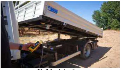
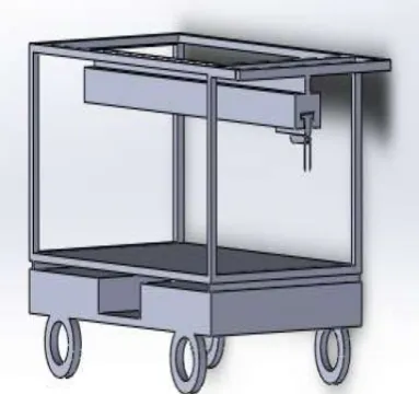
Fig 2.2 single side lifting truck
Objective
To provide a discharging unit that suits for easier collection of the grains or particles present
in the tipper. To control the rate of discharge at the discharging unit by introducing a control
valve. To change the direction of unloading method use in the tipper. To make the particles
dropped at the required places, rather than in only one direction. To perform the unloading
operation at very small and complex positions present between buildings.To make the loading
of heavy particles easier. To reduce the man power required loading of heavy particles. To
reduce the time consumption required for loading the heavy particles. To lift any load easily
without more man power.
Features
Grains discharge
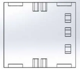
The introduction of new discharging units in a tipper will be very helpful for the discharging the grains or loads that is packed in bags. Such a discharging unit designed and it as follows. The bottom of the tipper is made into holes and these holes are attached with a tunnel shaped object for easier collection of material. Each hole represents each discharging unit. These holes are closed with the help of a lid. This lid is technically termed to be a control valve, as it can control the rate of discharge of the grains or loads from the tipper. The discharging units are totally independent and they does not depends on each other. That implies the opening or closing of one discharging unit does not affects the operation of another discharging unit. All of the discharging units can be opened or closed at the same time, that is dependent upon the requirement.
[Francis* et al., 4(4): April, 2017]
ISSN: 2349-5197
Impact Factor: 2.715
I
NTERNATIONAL
J
OURNAL
OF
R
ESEARCH
S
CIENCE
&
M
ANAGEMENT
Fig 4.1.2 tipper bottom
Tipper rotation
[Francis* et al., 4(4): April, 2017]
ISSN: 2349-5197
Impact Factor: 2.715
I
NTERNATIONAL
J
OURNAL
OF
R
ESEARCH
S
CIENCE
&
M
ANAGEMENT
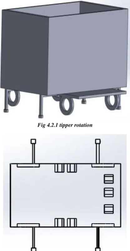
Fig 4.2.1 tipper rotation
Fig 4.2.2 bottom view
[Francis* et al., 4(4): April, 2017]
ISSN: 2349-5197
Impact Factor: 2.715
I
NTERNATIONAL
J
OURNAL
OF
R
ESEARCH
S
CIENCE
&
M
ANAGEMENT
Weight lifting
The loading of heavy particles on a tipper is very difficult as it requires more man power or any other special lifting vehicles.. If a machine or a mechanism that can lift such heavy particles is attached to the tipper, that would be greatly helpful. Our mechanism fulfills such requirements . The roof of the tipper, that is the top covering unit is attached to a motor that can move horizontally over the roof. The supports used to fix the roof must be tough enough to withstand the fractures done while lifting heavy loads. The motor has a arrangement of chain that is used to tie the heavy particle which is to be lifted. When the motor is operated it drives the chain and lifts the load to the surface of the tipper.
Fig 4.3.1 weight lifting rail wheel
Fig 4.3.2.side view of rail
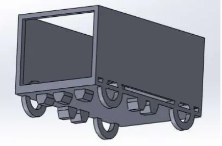
Brief description of drawing
Fig 2.1 and 2.2 represents the existing truck models, with lifting facility at only one side using hydraulic piston. Fig 4.1.1 Denotes the bottom of the tipper, that is provided with grain discharge units and control valves. Fig 4.1.2 Represents the two-dimensional layout of bottom view of the newly designed tipper
[Francis* et al., 4(4): April, 2017]
ISSN: 2349-5197
Impact Factor: 2.715
I
NTERNATIONAL
J
OURNAL
OF
R
ESEARCH
S
CIENCE
&
M
ANAGEMENT
Fig 4.2.2 Intimates the two dimensional bottom view of the tipper that can rotate.
Fig 4.2.3 Represents the actions of the additional hydraulic frames that takes place before the rotation of the tipper. Fig 4.3.1 Represents the isometric view of the weight lifting device that is designed in the tipper.
Fig 4.3.2 Represents the side view of the weight lifting rail and the rotating gears present in the mid portion.
Conclusion
Our design is reasonable , and it will overcome the existing problems in loading and unloading of tippers. The rotation of tippers is provided with necessary arrangements to prevent the vehicle from being disturbed from its equilibrium position
References
[1] DESIGN AND FABRICATION OF MULTI PURPOSE AGRICULTURAL EQUIPMENT by R Jaffar
Sadiq, Dr.S.G.Gopala krishna, Dr.N.G.S.Udupa ,NCET.Banglore.
[2] AHMAD MOHSENIMANESH “Modeling of pneumatic tractor tyre interaction with multi‐layered soil.
[3] Design of a multipurpose agricultural vehicle and attachments for developing countries David D. Wilson
and John H. Lumkes
[4] Modelling and Analysis of Multifunctional Agricultural Vehicle by Kshirsagar Prashant R ,Kuldip
Ghotane , Pritesh Kadam , Omkar Arekar , Ketan Insulkar.
[5] Sirisak Chertkiattipol , Tanya Niyamapa , Wanwisa Jantaradach , and Kridsada Saensuwan“The
performance of rotary power tiller using prototype rotary blades in dry-land field.
[6] Jeevarathinam A. Velmurugan C. Design modification and analysis of rotavator blade IOSR