Laboratory Study on Grout Injection for Improving Subgrade
of Airfield Pavements
Teck Shang Goh
1,*and Osamu Takashi
21WCT Berhad, No. 12, Jalan Majistret U1/26 Seksyen U1, Lot 44, Hicom-Glenmarie Industrial Park, 40150, Shah
Alam, Selangor Darul Ehsan, MALAYSIA.
2Department of Civil and Environmental Engineering, Nagaoka University of Technology, 1603-1 Kamitomiokamachi,
Nagaoka Niigata 940-2188, JAPAN.
Received 15 September 2014; accepted 20 December 2014; available online 28 December 2014
1.
Introduction
Pressure grouting is a common method used to modify soil properties in order to improve the bearing capacity, reduce permeability and deformability of the soil formation. The method is not new, however, the effectiveness of the method is difficult to evaluate. It is influenced by various factors and relies upon on-site experience and engineering judgments.
Grouting was used to improve the weakened subgrade soil of airport pavements at Kuala Lumpur International Airport in Malaysia. The method was chosen because it was easy to apply and cost effectiveness than many other soil improvement techniques. The advantages were: (1) the work could be carried out without damaging pavement surfaces, (2) the work areas could be re-open to traffic several hours after grouting and (3) no need to replace the existing soil materials. This would minimize the impact of daily airport operations. Because the funding for the rehabilitation project was restricted, the grouting work was carried out without developing an initial investigation to predict the grouting performance. It is important to conduct a grout trial program, hence the test results can be used as a reference for refining the method of rectification. Recognizing the importance of grout trials, a laboratory study was conducted to investigate the effectiveness of grout injection in soil strengthening.
The performance of grout materials with different water to cement ratio was made clear by previous researchers [1,2]. However the strength in the ground after grouting has not been sufficiently known. The objective of this study was to investigate the effect of cement grout mixtures and its penetrated distance in the treated area. Information on the KLIA case history was taken into account for the study.
2.
Case History of Grouting Work in KLIA
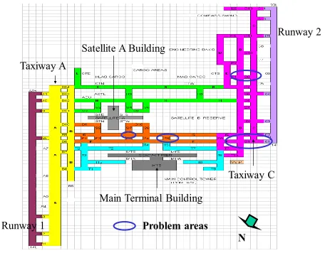
Fig. 1 illustrates the airfield layout plan of KLIA and also the areas of grouting work [3]. The grouting work was carried out at Rapid Exist C1, D and F. About 4,600 m2 of airfield pavements had depression. The areas were
located on the landfill areas. The standard penetration tests (SPT) and cone penetration tests (CPT) were conducted inside of boreholes. The subgrade soil was generally orange-brownish in color and mainly consisted of fine sand, silt and clay. In general, the SPT results indicated that the subgrade soil was loose. The average N value at the depth of 1.5 m to 2.5 m was 7-8 [4].
The rectification works comprised of five stages including removal of the fittings of airport ground lights (AGL) at the affected areas, grouting work, milling work, resurfacing of wearing course and reinstate the AGL fittings. The closure time for the grouting work was from 8.30 a.m. to 5.30 p.m. and normal airfield operation
Abstract: This paper shares the authors’ experience of using low pressure grouting to improve the subgrade
performance. The first part of the paper introduced a case history where low pressure grouting was applied in weakened subgrade of the active airport pavements in Kuala Lumpur International Airport (KLIA). The treated areas seemed to have been improved and only one of all eight treated areas had reoccurrence of depression. However, the performance of the treated area was difficult to be evaluated. The latter part of the paper investigated the effectiveness of grout injection through laboratory experiments. The laboratory equipment used for the grout injection tests included an injection mold and a steel tank of 1 m length x 0.6 m wide x 0.6 m depth for subgrade soil sample. Three grout types namely neat cement grout, fly ash cement grout, bentonite cement grout were used for this study. Six tests were conducted on sandy soil samples to examine the effect of grout type on the effectiveness of injection. The sandy soil was compacted to approximate 80 % of the maximum dry density. The injection pressure was fixed at 0.5 MPa. Insitu CBR test was also conducted to determine the strength of the grouted sample. The results showed that the fly ash cement grout could penetrate further than the neat cement grout; however its strength was lower than the neat cement grout.
resumed at night. The work areas would be closed section by section.
The tube a manchette (TAMS) system was used. The grouting mechanism was as follows. A starting pressure of 25 bars was used to break through the rubber sleeve covering openings in the manchette tube. Once the grout began to flow into surrounding soil, the injection pressure was reduced to 2 to 5 bars. The injection material was the cement grout mix. The water to cement ratio was 1:1. The grout slurries under pressure would fill up the fissures. Thus it would create the reinforcement in the surrounding area. The method was accepted for implementation as it could be applied in all range of soils [5].
Runway 2
Runway 1 Taxiway A
Taxiway C
Main Terminal Building Satellite A Building
N Problem areas
Fig. 1 KLIA layout plan indicated the problem areas.
The grout holes were laid out in a grid pattern on a spacing of 2.5 m each way. The depth of grouting was between 1.5 m to 2.5 m below the pavement. The cement grout was injected into the ground until the refusal was reached. After injecting every 10 bags of cement, ground survey was carried out to check the ground surface. This was to monitor the sign of surface heaved due to grouting.
Elevation survey was carried out to monitor the surface unevenness of airport pavements in the following times; immediately following completion of the grouting, completion of resurfacing work, at 60 days, 180 days and 360 days later. It was found out that one of the treated areas, C1 had shown severe depression. Re-grouting was conducted during the period of defect liability. No further deformation has been noted thereafter.
Five years later, the airport authority carried out a non-destructive testing (NDT) to evaluate the pavement structure for the purpose of upgrading works for new large aircraft A380 operations. The surface deflections in NDT were measured by Falling Weight Deflectometer. Visual distress survey was conducted using Pavement Condition Index method. Runway roughness condition evaluation, samples coring and dynamic cone penetration (DCP) tests were also carried out [6]. The test results generally indicated that the airport pavements were in good condition except at Taxiway C1, C2 and D2, which indicates a loading failure problem. The PCI values rating
the surface characteristic of those sections were fair. However, the data of DCP test showed that the subgrade strength of treated areas were higher than un-treated areas. When the test result of dynamic cone penetration was converted to equivalent CBR value, for example, the CBR for Runway 1 (untreated area) was ranged from 11% to 44%. The treated areas such as Taxiway F had a CBR value ranging from 21% to 95%. The treated area at Taxiway C1 was 53% [5]. This indirectly showed that the bearing capacity of the subgrade had been increased via grouting. However, the actual grout penetration was difficult to quantify and conclude. Some questions such as the effectiveness of grout material, how far the grout could be penetrated, what was the appropriate distance to locate the grout hole remain as the issue that should make clear.
3.
Laboratory Study of Grout Injection for
Weakened
Subgrade
of
Airfield
Pavements
One of the research objectives of this study was to investigate whether the grouting has the potential to increase the strength to 9% of CBR value. The strength of the subgrade soil of Haneda Airport in Japan was increased from 3% to 9% via soil mixing method with 2.6% of lime [7]. If the treated ground of airport pavement in Haneda is weakened after operation, the result of this study can be used as a reference for comparing solutions and refining appropriate rectification method.
3.1 The grout injection equipment
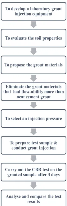
To have a better understanding on grout spread, a grout injection model was developed. The study approach is shown in Fig. 2. The overview of the grout injection model is shown in Fig. 3. The grout injection model consists of a centrifugal compressor (act as a pump), injection equipment with an injection mold, pressure meter, control valves, a grout delivery line (nylon tube) and an injection sleeve pipe. The direct injection system was used in this study. The injection mold could contain 4 liters of grout mix at one time. The grout mix was delivered to the injection pipe via a nylon tube. This injection system had three valves; one was to control the injection pressure, one was to control the grout volume from the injection mold to the delivery line and one was to control the grout volume from the injection pipe into the soil. Four nozzle holes for injection with 3.5 mm diameter were created surrounding at the injection pipe. The injection rate was directly related to the injection pressure. The injection pressure was controlled via adjusting the control valve. A lot of initial works were carried out to ensure the results produced by the equipment were reliable.
Fig. 2 Overview of the grout injection test model.
3.2 The soil sample
The soil sample of subgrade was collected from the embankment of Agano River of Kanto area in Japan. It was a fine to medium soil. The soil sample was selected because of the low CBR value ranged from 2% to 3%. The characteristics of the soil sample had the similarity to the subgrade condition at Haneda Airport. The subgrade
soil test section was prepared in 600cm x 100cm x 60cm of soil tank for grout injection test. The subgrade soil was compacted to an approximate 80% degree of compaction. This was to simulate the weakened soil condition. No movement of ground water was assumed in this study.
3.3 The grout mix
Cement grout mixtures were chosen as an injected material. It is the most economical and has been used for a long period. The grout mix was designated by water to cement ratio, where the components were proportional on a weight basis. Two ratios of cement grout mixes was examined, namely 1:1 water to solid ratio (w:s) mix and 2:1 w:s ratio mix. The w:s ratio of 1:1 mix had been used in KLIA project, and the w:s ratio of 2:1 mix was proposed based on the literature review [2,4]. The w:s ratio of 1:1 mix was expected to provide sufficient strength to increase the strength of grouted masses. The w:s ratio of 2:1 mix was expected to have a farer-grouted zone.
Cement used for this study was ordinary Portland cement. Three types of cement grouts mixes were studied in this experimental work. One was the water to cement base grout, called neat cement grout, and the others were fly ash cement base grout mix and bentonite cement grout mix. Fly ash was chosen as it has the effective pozzolanic characteristic and without much affect to the viscosity. Bentonite was chosen as it has the ability to reduce bleeding [4,8]. However it would increase the viscosity and cohesion of the mix. In the literature, the content or proportion of the fly ash used in concrete mixture design and soil mixing was well defined by the designer [9]. Generally, high content of fly ash is suggested in concrete mix and soil mixing. However, it is not the same for the grout mix design. The use of fly ash or bentonite for grout mix has not been well established.
For this study, the fly ash and bentonite were as partial substitute for Portland cement in two of the test sections. According to the guideline issued by U. S. Army Corps of Engineers, the maximum amount of fly ash should not exceed 30 percent of the cement by weight so that a replacement material of the cement will not affect the strength and durability [10]. This study followed the recommendation that 30 % of the cement content was substituted with fly ash and bentonite each. One of the test sections, approximate 2 kg of fly ash was added in the 2:1 w:s cement grout mix.
Table 1 shows the list of the proposed grout mixtures and their flow cone test results. Flow cone test were carried out to determine the viscosity of the grout. The viscosity of w:s ratio of 1:1 mix and 2:1 mix were 14s and 11s. By adding approximate 2 kg of fly ash in w:s ratio of 2:1 neat cement grout mix, the viscosity was increased from 11s to 12s. It had very little effect on viscosity value. The viscosity of w:s ratio of 1:1 fly ash cement grout mix had a flow-ability of 16s. For the w:s ratio of 2:1 fly ash cement mix, the viscosity was 12s. The viscosity of w:s ratio of 1:1 bentonite cement grout mix had increased viscosity and cohesion. The cement
To develop a laboratory grout injection equipment
To evaluate the soil properties
To propose the grout materials
Eliminate the grout materials that had flow-ability more than
neat cement grout
To select an injection pressure
To prepare test sample & conduct grout injection
Carry out the CBR test on the grouted sample after 3 days
Analyse and compare the test results
grout mix became a very thick cement paste that not able to flow through the flow cone. This grout mix would not be selected for further grout injection test. The w:s ratio of 2:1 bentonite cement mix had the viscosity of 15s.
Table 1 Proposed grout mixtures and their flow cone test.
No Mix ID Flow cone Average
test (s) 1 1:1 w:s ratio of neat cement grout mix 14
2 2:1 w:s ratio of neat cement grout mix 11
3 2:1.5 w:s ratio of fly ash cement grout mix 12
4 1:1 w:s ratio of fly ash cement grout mix 16
5 2:1 w:s ratio of fly ash cement grout mix 12
6 1:1 w:s ratio of bentonite cement grout mix ability (>60s) Low
flow-7 2:1 w:s ratio of bentonite cement grout mix 15
3.4 The grout intake
The groutability is the accepted of the grout by the types of soils. The broad general classification of soils is an index to groutability. The groutability ratio of the soil is D15 of the soil /D85 of the grout [11]. The groutability ratio of this study was 16, smaller than 25. It meant that cement grout might not be sufficiently penetrated, as the particular size of the soil might not be fully accepted by the soil sample.
3.5 The injection pressure
The fractures in soil are different from each soil types. The opening in soil by fractures would facilitate the grout penetration. The question was at what injection pressure the fractures would start and expand or propagate. Water injection test was carried out to select a suitable injection pressure for the grout injection test. Four liters of water would be injected into the soil sample, at an injection pressure of 0.1, 0.3, 0.5 and 0.7 MPa respectively. The moistures of the injected samples were measured to evaluate the distance of the penetrability. Fig. 4 shows the result of the water injection test.
It is observed that the water-penetrated distance was up to 60 cm from the injection hole at 0.1 MPa. However, injection pressure of 0.1 MPa might not be sufficient to push the cement grout slurries to the desired penetrated distance. The data from 0.3 MPa injection pressure was not as good as 0.5 Mpa and 0.7 MPa. The water penetration caused by 0.7 MPa was the highest among all. However the water penetration reduced dramatically thereafter. The water-penetrated distance was limited at 60 cm. It meant that high-pressure injection might cause
turbulent. The entering fluid flowed away from this zone in all directions. However, the turbulent through the total treated area was not desired as it would result internal friction and reduced the flow volume. As a result, the grout-penetrated distance might be less than the expected one. Thus 0.5 MPa was chosen for this study. The data shows that the injection pressure of 0.5 MPa was sufficient to inject the water up to 60 cm. It could also provide sufficient fractures in soil and facilitated farer penetrability than that of 0.3 MPa and 0.7MPa.
Fig. 3 Water penetrated distance by different injection pressure.
Wet soil samples were taken at the depth of 5 cm, 10 cm and 15 cm respectively. It is observed that the water penetrated in the soil varied at different depth of the sample. Fig. 5 illustrates the detailed data of water-penetrated distance at an injection pressure of 0.5 MPa. The data indicated that the moisture content at 15 cm depth was higher than that at 10 cm, and the moisture at 10 cm was higher than that at 5 cm. This shows that when the injection stopped, the water flow tended to sink under the action of gravity. At here, it was assumed that the grout would perform the same way as water.
Fig. 5 Water penetrated pattern by 0.5MPa injection pressure.
refusal. The result showed that the refusal reached at 14 liters within 5 minutes. The flow rate was 2.8 liter/minute. This predicted that the injected volume of grout for 20 cm thickness of test soil should be less than 14 liters.
3.6 The test procedure
The test procedures for the grout injection are as follows:
1) The subgrade soil samples were constructed to 20 cm thickness in the soil tank, and all samples were compacted to approximate 80% degree of compaction by a handy compactor.
2) The density and the strength of the sample were measured before the injection test. The density was measured by using sand cone method.
3) The grout mix was prepared and the flow-ability of the grout mix was measured by flow cone test. 4) Make an injection hole of 100 mm so that the
injection pipe could be inserted into the soil sample. The annulus gap between the pipe and the injection hole was sealed with cement sand.
5) Set the injection pressure to 0.5 MPa and start the injection of the grout. The grout injection process was monitored by observation. The flow rate was controlled at 1 liter/minute.
6) Measure the strength of the grouted sample at every 20 cm, 40 cm, 60 cm and 80 cm from the injection points by in-situ CBR test after 3 days. The in-situ CBR tests were conducted according to ASTM standard. Fig. 6 shows the layout plan of the test section and the location for CBR test. The injection point was at 10 cm.
(cm)
(cm)
v
0 10 20 30 40 50 60 70 80 90
60
5
0
4
0
3
0
2
0
1
0
Fig. 6 The location for CBR test.
4.
Test Results and Analyses
In this study, nine test sections of the subgrade soil samples with 20 cm thickness were constructed and tested. Three out of the nine grouted samples were failed due to quick surface heaved. It was difficult to control the grout flow rate.
4.1 Strength and grout penetrated distance
The strength of the grouted sample was affected by a) the type of grout mix to be added, b) the injection pressure, c) the injected volume that could be accepted by
the type of soil. In this study, since the the injection pressure was fixed at 0.5 MPa, the affected factors were the grout materials and the acceptance of the grout based on the soil type. Table 2 presented the average CBR values and grout-penetrated distance achieved by each grout mixes. In general, the strength of all grouted samples was increased. Out of the six test sections, only the 1:1 w:s ratio of neat cement grout mix could increase the CBR value to 9%. It had the CBR values ranged from 3% to 14%. The effective grout penetrated distance was 60 cm from the injection point. This confirmed the situation that mentioned in literature review, the greater ratio of water to cement, the lower the viscosity will be; thus the strength was reduced [4, 12].
The 2:1.5 w:s ratio of fly ash cement grout mix had the second highest CBR values. The CBR values was ranged from 5.1% to 8.5%. The grout was able to penetrate up to 80 cm from the injection point. The grout seemed to be more stable and sustained longer pumping distance. Adding high volume of fly ash into neat cement grout not only improved the flow properties of grout but also greatly increased the strength to acceptable subgrade strength condition. The pozzolanic characteristic contributed to bond the soil where the Portland cement could not be reached. This confirmed with other researchers’ statement that adding additives into the grouts could improve the stability and rhelogical properties of the grouts in order to enhance the penetrability and flow characteristic of the grouting material [4,8].
Table 2 The strength of grouted samples with the respective cement grout mixes
Mix ID
CBR value after 3 days per penetrated distance (%) 30
cm cm 50 cm 70 cm 90 Ave. 1:1 w:s ratio neat
cement grout 14.0 11.3 4.5 3.0 8.2 2:1 w:s ratio neat
cement grout 5.2 5.7 5.0 4.2 5.0 2:1.5 w:s ratio fly ash
cement grout mix 8.0 8.5 6.5 5.1 7.0 1:1 w:s ratio fly ash
cement grout mix 5.6 5.6 5.3 3.4 5.0 2:1 w:s ratio fly ash
cement grout mix 4.4 4.8 4.0 3.8 4.3 2:1 w:s ratio bentonite
cement grout mix 6.4 6.5 5.3 4.1 5.6
a more cohesive mix. Thus, a more stable grout was injected into soil.
Even though fly ash had the pozzolanic characteristic, it is not as good as cement.The experiment results showed that fly ash was not a good replacement material of cement. The decrease of cement content and substituted with fly ash in both 1:1 w:s and 2:1 w:s grout mixes only increased the CBR value of 2% and 1.3%. It did not bring much benefit.
Fig. 7 The strength of achieved by the respective cement grout mixes.
Fig. 8 shows the photographs of an untreated sample and a grouted sample. When a fine-grained soil was treated with amount of cement, the cement hydration products would bind some particles together to form larger grains in the size range of fine sand particles. It created reinforcement effect.
2. Experiment work
Fig. 8 Photograph of the untreated sample (left) and grouted sample (right).
4.2
Grout intake
In this study, besides the behavior of the grout materials, the acceptance of the grout into the subgrade soil would also affect the strength of the grouted sample. Table 3 presents the data of the injection volume of respective test sections. Generally, after 9 liters of grout
was injected, the soil layer was lifted. The soil was not able to accept the grout any more. This volume represented approximate 8% of subgrade soil sample. This was in line with the water injection test, the volume of grout that could be injected into the sample was low.
To investigate whether there is any difference due to the thickness of soil sample, the soil sample thickness was increased to 30 cm. A 50 cm of asphalt layer was laid above the soil sample. The 2:1 w:s fly ash cement grout was injected into the soil. Similar situation occurred, the refusal of grout also reached at about 9 liters. The over flow occurred at the injection point and also at certain weak points. The experiment results indicated that, the grout intake for one grout hole under 0.5 MPa was low. The penetrated distance was approximate 80 cm from the injection hole. For the same type of soil and soil thickness, the allocated spacing between two grout holes could be designed at 160 cm.
Table 3 The grout intake of the respective samples
No Mix ID volume (l) Injected increased (%) Volume
1 1:1 w:s ratio neat cement grout 7 6%
2 2:1 w:s ratio neat cement grout 11 9%
3 2:1.5 w:s ratio fly ash cement grout 9 8%
4 1:1 w:s ratio fly ash cement grout 8 7%
5 2:1 w:s ratio fly ash cement grout 10 8%
6 2:1 w:s ratio bentonite cement
grout 9 8%
Average 9 8%
5. Conclusions
The conclusions of this research are summarized as follows.
i. The grout injection appeared to have a good potential to increase the CBR values to an acceptable strength level.
ii. The used of high volume of fly ash in 2:1.5 w:s cement grout had farer penetrated distance. The increased in strength was more than the 2:1 w:s neat cement grout mix.
iii. With the injection pressure of 0.5 MPa, the grout was generally could penetrate to 80 cm. The spacing between grout holes can be designed be at 160 cm for the same types of soil.
Acknowledgement
special thanks to all the members of Transportation Engineering Laboratory in Nagaoka University of Technology for their various support and kindness.
References
[1] Heenan, D., and Naudts, A. Advanced grouting program at Penn Forest Dam results in reduced construction costs and high quality product. Paper online: http://www.ecogrout.com, (2000), pp.1-9. [2] James, W. Practical handbook of grouting: soil, rock
and structures. John Wiley and Sons, Inc: Hoboken, New Jersey (2004), pp.1-720.
[3] Soil Central Lab Sdn Bhd. Deep sounding test report for runway 2, taxiway C, D and F. Unpublished Document, (2001).
[4] Kuala Lumpur International Airport Berhad. Contract document of rectification work for rapid exit C, taxiway D and taxiway F, Project Report, Volume 1, Unpublished Document, (2001).
[5] Munfakh, G.A., and Wyllie, D.C. Ground improvement engineering issues and selection. Paper online: http://lib.jzit.edu.cn, (2000), pp.1-27.
[6] Malayisa Airport Sepang Sdn Bhd. Non-destructive testing and pavement evaluation work. Project
Report, Volume 2, Unpublished Document, (2005), pp. 1-37.
[7] Port and Airport Research Institute. Subgrade soil improvement work of Haneda Airport. Project Report, Unpublished Document, (2004), pp. 3-4. [8] Mikkelsen, P.E. Cement bentonite grout backfill for
borehole instruments. Paper online: http://slopeindicator.com, (2002), pp. 38-42.
[9] Naudts, A., Eric, L., Stephen, H., and Ward, N. Additives and admixtures in cement based grouts. Paper online: http://www.ecogrout.com, (2003), pp. 1-14.
[10]US Army Corps of Engineers. Engineering and design in grouting technology. Paper online: http://www.usace.army.mil, (1984),pp. 1-159. [11]Mitchell, J.K. Soil improvement: state of art. Proc. of
Tenth International Conference on Soil Mechanics and Foundation Engineering. Stockholm, Sweden, (1981), pp. 509-565.