Dung Vo Tien 1, Radomír Gono 1 and Zbigniew Leonowicz 2,* 4
1 Department of Electrical Power Engineering, FEECS, VSB, Technical University of Ostrava, Ostrava, Czech 5
Republic; {Dung.vo.tien.st, radomir.gono}@vsb.cz 6
2 Faculty of Electrical Engineering, Wroclaw University of Science and Technology, Wroclaw, Poland; 7
* Correspondence: [email protected]; Tel.: +48-71-320-2626 9
10
Abstract: Power quality is a major concern in electrical power systems. The power quality 11
disturbances such as sags, swells, harmonic distortion and other interruptions have impact on the 12
electrical devices and machines and in severe cases can cause serious damages. Therefore it is 13
required to recognize and compensate all types of disturbances at an earliest to ensure normal and 14
efficient operation of the power system. To solve these problems, many types of power devices are 15
used. At the present time, one of those devices, Dynamic Voltage Restorer (DVR) is the most 16
efficient and effective device used in power distribution system. In this paper, design and modeling 17
of a new structure of multifunctional DVR for voltage correction is presented. The performance of 18
the device under different conditions such as voltage swell, voltage sag due to symmetrical and 19
unsymmetrical short circuit, starting of motors, and voltage distortion are described. Simulation 20
result shows the superior capability of proposed DVR to improve power quality under different 21
operating conditions. The proposed new DVR controller is able to detect the voltage disturbances 22
and control the converter to inject appropriate voltages independently for each phase and 23
compensate to load voltage through three single- phase transformers. 24
Keywords: compensation techniques; dynamic voltage restore; harmonic distortion; power quality; 25
short circuit; voltage sag; voltage swell 26
27
1. Introduction 28
With the increasing amount of sensitive devices (power electronic devices) that are quite 29
sensitive to power quality disturbances in the supply network, the problem of compensation of 30
power quality disturbances is ever increasing. Power quality disturbances are categorized into 31
voltage sags, voltage swells, transients, harmonics, interruptions. It can cause many technical 32
problems (such as extra heating, mis-operation, early aging of the devices etc.) and financial losses to 33
the power system operators and the customers. There are different ways for improvement of power 34
quality such as Distribution STATic synchronous COMpensator (DSTATCOM), Dynamic Voltage 35
Restorer (DVR), Active Filter (AF), Unified Power Quality Conditioner (UPQC), etc. Among these, 36
the DVR is one of the most effective and cost-efficient devices, which can used in power distribution 37
system. 38
Using DVR in the distribution system for power quality improvement has been analyzed and 39
proposed through many publications [1]-[18]. However, these research consider the solution for 40
each case, for example for mitigating voltage sags due to starting motors [9], or short circuits [4], [5], 41
[6], [13], mitigating balanced voltage sags and swells [6], compensating fluctuations and distortions 42
of voltage [2]. In this paper, the DVR is used for power quality improvement of any type 43
(multifunctional DVR), providing the solution for all cases above. The detailed configuration of DVR 44
is described in Section 3, and the multi-loop controller using PI (Proportional- Integral) controller 45
developed on the rotating coordinate system is presented in Section 4. A multifunctional DVR is 46
modeled using MATLAB-Simulink and tested for voltage swell, voltage sag due to starting motor, 47
symmetrical and unsymmetrical short-circuit and voltage distortions. Simulation results show the 48
capability of the DVR to control the fault and disturbance conditions of the distribution system. 49
2. Most Common Power Quality Problems 50
Although the problems described in this section are well known, for the sake of completeness, 51
we review shortly here the fundamentals of power quality problems. Power quality can be defined 52
as the ability of the power system to provide their customers with an uninterrupted flow of energy at 53
ideal sinusoidal waveform. Various power quality problems can be categorized as voltage sags, 54
swells, harmonics, transients, interruption considered are the most common power quality problems 55
in electrical distribution systems. Common Power quality problems are described briefly below, 56
following [2], [14], [15]. 57
Voltage sag or a dip is short duration reduction of amplitude, it occurs when the RMS of voltage 58
decreases between 10 to 90 percent of nominal voltage for one-half cycle to one minute. It is one of 59
most frequent disturbance in the distribution system. It is caused by faults in the power system, 60
transformer energizing or by the starting of a large induction motors, among other causes.. 61
Voltage swell is the opposite to voltage sag, it happens when the RMS of voltage increases 62
between 10 to 80 percent of nominal voltage for one-half cycle to one minute. It is not as common as 63
voltage sag. The main causes for voltage swells are switching of large capacitors or start/stop of 64
heavy loads, among other causes. 65
Interruption is defined as a reduction in voltage or current to less than 10 percent of nominal, 66
not exceeding 60 seconds in length. Sustained interruption happen when the supply voltage or 67
current falls to zero for more than 1 minute. These are the result of faults, equipment failure, control 68
malfunction or improper breaker tripping. 69
Harmonics are the waves with frequencies that are the integral multiple of the frequency of 70
reference wave (at which supply system is designed to operate). 71
Transient is defined as a short duration surge of electrical energy in power system caused by a 72
sudden change of state. There are two types of transients: impulse and oscillatory. The main causes 73
for harmonic distortion are rectifiers and, in general, all non -linear loads. 74
3. Multifunctional Dynamic Voltage Restorer 75
3.1. Configuration and components 76
The DVR is a power-electronic-converter-based device capable of protecting sensitive loads 77
from most supply-side disturbances [11]. A DVR is installed in a distribution system between the 78
supply and a sensitive load feeder at the so-called point of common coupling (PCC). Its primary 79
function is to rapidly inject/absorb additional energy in the system in order to avoid any power 80
disruption to that load event of disturbances in the system. The general structure of a DVR consists 81
of a booster transformer, a harmonic filter, a voltage source converter (VSC), and an energy storage 82
84
Figure 1. Configuration of DVR in the Power Distribution System. 85
3.1.1.Injection/booster Transformer 86
The injected voltage is supplied into the distribution system through an injection transformer. It 87
connects the DVR to the distribution system via HV- winding and transforms the injected 88
compensating voltage generated by the Voltage Source Converter (VSC) to the supply voltage after 89
the detection of any disturbance by the controller. In addition, the injection transformer serves the 90
purpose of isolating the DVR circuit from the system. For compensating unbalanced voltage sags, 91
three single-phase transformers can be used, however, this increases the size and cost of the DVR. To 92
select a suitable injection transformer into the DVR, the MVA rating, the primary winding voltage 93
and current ratings, the turn-ratio and the short–circuit impedance values of transformers are 94
required. 95
3.1.2. Harmonic Filter 96
The main task of the harmonic filter is to keep the harmonic voltage content generated by the 97
VSC at the permissible level. The filter is placed to damp the switching harmonics generated by the 98
PWM control of VSC. 99
3.1.3. DC- link and Energy Storage Unit 100
The main function of these energy storage units is to provide the desired real power during the 101
voltage sag. Two types of systems are considered; the first where energy is taken from the incoming 102
supply through a shunt converter, and the second where energy storage devices such as flywheels, 103
batteries, superconducting magnetic energy storage (SMES) and super capacitors are used [3]. The 104
energy storage devices have the advantage of fast response. 105
3.1.4. The Voltage Source converter 106
A VSC is a power electronic system that consists of a storage device and switching devices, 107
which converts the dc voltage from the energy storage unit to a controllable three phase ac voltage. 108
The inverter switches are normally fired using a sinusoidal Pulse Width Modulation (PWM) scheme. 109
In multifunctional DVR, the VSC can be operated with unbalanced switching functions for three 110
phases, and deal with each phase independently. Normally the VSC is not only used for voltage 111
3.2. Compensation Techniques 113
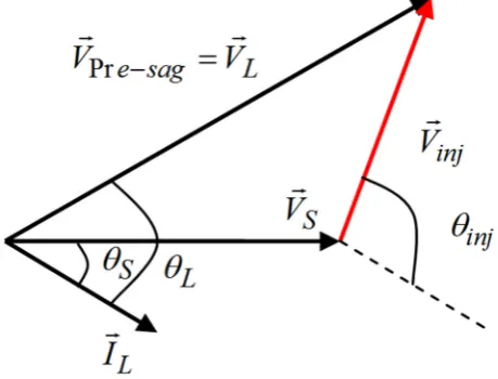
For the proposed DVR, the pre-sag compensation method is chosen because it is the best 114
compensation strategy to restore controlled pre-sag magnitude without phase change. The 115
magnitude and the angle of the injected voltage are 116
2 2 2 cos( )
inj L S L S L S
V = V +V − V V θ −θ
(1) 117
1 sin sin
tan ( )
cos cos
L L S S
inj
L L S S
V V
V V
θ θ
θ = − θ − θ
− (2)
118
However, the disadvantage of this method is that the injected active power is not controlled so 119
high capacity energy storage is required
.
120121
Figure 2. Phasor diagram of the pre-sag compensation technique. 122
3.3. Operation Modes of DVR 123
The DVR has three modes of operation: protection mode, standby mode (during steady state), 124
and injection/boost mode (during sag/swell). In Protection mode, the DVR is protected from the over 125
current on the load side due to short-circuit on the load or large inrush current. The DVR can be 126
isolated from the system by using the by-pass switches as shown in Figure 1. In standby mode, no 127
switching of semiconductors occurs and the load current will pass through the transformer primary 128
winding. In boost (Injection) mode, when the voltage disturbance occurs in the supply is detected, 129
the DVR will be injected a compensation voltage through the voltage injection transformer. 130
4. Control Techniques of DVR 131
In general, the process control of DVR includes 3 steps: 1. Detection of voltage sag/swell 132
occurrence in the system, 2. Comparison with the reference value and 3. Generation of gate pulses to 133
the voltage source inverter (VSI) to generate the DVR output voltages which compensates/absorbs 134
the voltage sag/swell. 135
4.1. Grid Synchronization Techniques 136
Synchronization to the supply voltages is very important in order to control the DVR. It keeps 137
an output signal synchronized with a reference input signal in frequency and phase. 138
Synchronization methods have been developed and presented in many publications [16]-[18]. The 139
most often used synchronization method in engineering applications, the phase-locked loop (PLL) 140
142
Figure 3. Phase locked loop to synchronize the DVR to the supply voltages. 143
Figure 3 shows the block diagram of three phase PLL. The voltages measured at PCC bus (Vabc) 144
is transformed from three phase frame to αβ frame using Clarke’s transform. 145
1 1
1
2 2 2
3 3 3
0
2 2
a
b
c V V
V V
V α
β
− −
=
−
(3)
146
and transformed from αβ frame to synchronously rotating dq frame using Park’s transform 147
cos sin sin cos d
q
V V
V V
α β
θ θ
θ θ
=
−
(4)
148
The Loop Filter is a low-pass filter, it is used to suppress high frequency components. The Loop 149
Filter provides controlled signal to voltage controlled oscillator (VCO) which work as an integrator. 150
Typically, this block is constituted of a first-order low-pass filter or a PI controller [16]. The 151
output of the PI controller is the inverter output frequency that is integrated to obtain inverter phase 152
angle θ. The PI regulator of the LF will set the angular position of the dq reference frame to make 153
Vd=0 in the steady state, which means that the PLL will be active when the difference between grid
154
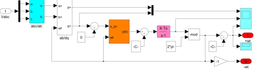
phase angle and inverter phase angle is reduced to zero. The model of PLL in MATLAB-Simulink 155
environment is present in Fig.4. 156
157
Figure 4. The MATLAB-Simulink model of PLL. 158
4.2. Sag/swell Detection Techniques 159
The voltage sag/swell phenomena are necessary to detect the starting point, the end point, sag 160
depth and phase shift. There are many different methods for detecting voltage sag, swell, such as 161
peak value, root mean square (RMS), Fourier transform, Wavelet transforms and Space Vector 162
method. In the number of methods, Space Vector control is the most effective method which is used 163
widely in DVR applications. In this method, the three phase voltages Vabc are transformed into a 164
information of voltage magnitude and angle shift is compared with the reference value in the dq 166
frame, which had to be transformed back to the three-phase frame. 167
168
2 2
, ( , , ) ( , , )
err dq ref d PCC d ref q PCC q
V = V −V +V −V (5)
169
,
err dq threshold
V >V (6)
170 171
If the voltage dip contains a phase jump, it will lead to a reduction in both the d- and 172
q-component. Details of this case are described in [17]. Figure 5 shows the voltage sag/swell detector 173
model of DVR in MATLAB-Simulink environment. The proposed method can detect the change in 174
the state of the supply (the start, end points, and phase jump) with low time delay. 175
176
177
Figure 5. The MATLAB-Simulink model of the Detector. 178
4.3. Control Techniques 179
The control system is very important in DVR, with the requirements of fast response for of 180
voltage sags and variations in the supplied load. The main purpose of the control system is to 181
maintain the voltage magnitude of the sensitive load, where DVR is used, under system 182
disturbances. There are three main voltage controllers used, the Feed-forward (open loop), Feedback 183
(closed loop) and Multi-loop controller, and another controllers based on “artificial intelligence”, 184
such as Artificial Neural Networks (ANN), Fuzzy Logic (FL) and Space Vector Pulse Width 185
Modulation (SVPWM) for special conditions. The Feed-forward voltage controller is the primary 186
option for the DVR, because of its simplicity and fast response. The disadvantage of the open loop 187
controller is the high steady state error. The Feedback controller has the advantage of accurate 188
response, but it is complex and causes time-delays. Multi-loop control is used with an outer voltage 189
loop to control the DVR voltage and inner loop to control the load current. This method has the 190
strengths of feed-forward and feedback control strategies, it can improve the system dynamic 191
response rate, shortening the time of compensation significantly [1]-[3]. 192
193
The injected voltage that is needed to compensate by DVR is 194
* *
in j L g
u = u −u (7)
195
The structure of the multi-loop controller is shown in Figure 6. In this method, the three-phase 196
voltages of the grid are sensed and transformed to two-phase system (ab) in the stationary reference 197
frame and in the rotating reference frame (dq). Then, the positive sequence and the negative 198
sequence components are extracted. Positive sequence grid voltage vector is compared against the 199
positive sequence load voltage command vector. The difference between them becomes the desired 200
injected positive sequence voltage vector across the filter capacitor. The process of the negative 201
203
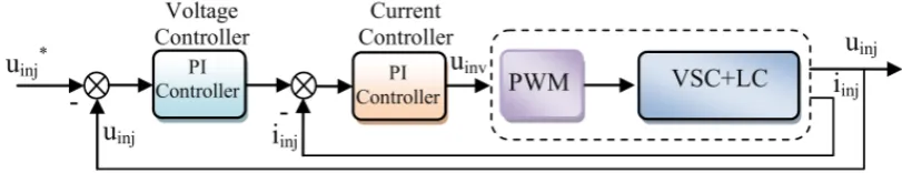
Figure 6. Block diagram of the multi-loop controller. 204
This controller has two measured process variables, injected current iinj and injected voltage uinj 205
and attempts to minimize the error between the desired *
in j
u and uinj. Two separate controllers for 206
each sequence (positive and negative) are used, and the current controller can regulate the injected 207
currents and improve response and proper operation of the voltage controller to restore the load 208
voltage. The controller based on PI control has been presented detail in [8]. The proposed new 209
controller is able to detect the voltage disturbances and control the converter to inject appropriate 210
voltages independently for each phase and compensate to load voltage through three single- phase 211
transformers. 212
213
5. Simulation 214
5.1. Modeling and simulation 215
The proposed multifunctional DVR is implemented in MATLAB-Simulink for mitigating of 216
balanced, unbalanced voltage sag/swell, fluctuations and distortions voltage. The simulations are 217
based on the real power system as shown in Figure 7 and the details of the system parameters are 218
given below 219
Source: 220
115kV, 50Hz, Ssc= 250MVA. 221
Transmission line: 222
R= 1.309 Ω, L= 9.24 mH. 223
Transformers: 224
T1: 25MVA, 110/6.3kV, Y/D1, Uk= 11.5% 225
T2: 2800kVA, 6.3/0.63kV, D/Yn11, Uk=5.8%. 226
Load: 16.87MW, 11.24MVAr 227
228
Sensitive load: 229
1975 kW motor, 0.63 kV, rated speed 1000 rpm. 230
231
The DVR is designed to protect the sensitive loads at voltage level 6.3 kV and its parameters are 232
below: 233
Energy storage: 234
Power rating: 1400kVA, VDC= 700V 235
Injection transformer: 3 single-phase transformers, 1500kVA, 0.63/6.3kV, Uk=5%. 236
Filter: 237
Lf= 7,109 mH, Cf= 6,942 μC. 238
Switches: IGBT 239
Switching frequency: 5 kHz. 240
241
242
243
245
Figure 7. The MATLAB-Simulink model of test system. 246
5.2. Results and Discussion 247
5.2.2. Case 1: Three phase balanced voltage sag. 248
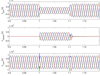
The balanced voltage sag at PCC due to three phase short circuit happens in the power system, 249
the voltage decreased to 50% from 1.00s to 1.10s. Figure 8 shows the simulated waveforms for the 250
grid voltages, the injection voltages of DVR and the load voltages during the sag event. Before the 251
sag, the DVR is in the standby state waiting for the sag detection. It can be observed that the DVR 252
compensates the balanced sag rapidly when the grid-side voltage sag happens. By this simulation, 253
the perfect performance of the grid synchronization algorithm and the control strategy is shown. 254
255 256
Figure 8. Case 1- Balanced voltage sag: grid voltage, injected voltage of the DVR and load voltage. 257
260
Figure 9. Case 2- Unbalanced voltage sag: grid voltage, injected voltage of the DVR and load voltage. 261
In this case study, from 1.00s to 1.10s, a phase to phase short circuit (between phase A and C) 262
occurred in power system, the voltage at PCC reduced to 35% in phase A, and to 28% in phase C and 263
increased slightly by 10% in phase B respectively to the reference pre-sag voltage and the phase 264
angle jump of grid voltage. The results of this simulation are shown in Figure 9. Observe that the 265
DVR quickly injects the necessary voltage components, with correct both magnitude and phase 266
angle to maintain balanced load voltages. It is shown that the DVR can detect and mitigate the 267
voltage sag in different phases independently and inject the compensation energy through 3 268
single-phase transformers to correct the grid voltage. 269
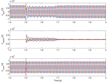
5.2.4. Case 3: Voltage sags due to starting of a motor. 270
A typical cause of voltage sags is caused by starting a large three-phase motor. The 271
characteristics of voltage sags depend on various factors, such as motor rating, the method of 272
starting and system’s power supply capacity. In this paper, the test system is simulated in the case of 273
starting 1975kW induction motor. The motor is started at 1,50 s by closing motor starting contactor. 274
The three phase voltage sag RMS waveform of grid voltage is shown in Figure 10. Voltage sag 275
caused by starting motor is unbalanced and drops down to 20% of its nominal value. 276
277
Figure 11 shows the simulated wave form of the grid voltage, injected voltage of the DVR and 279
load voltage when starting motor. The DVR generated unbalanced three phase voltages for each 280
phase to compensate grid voltage unbalance. As a result, the voltage sag is fully compensated, the 281
load voltage is maintained balanced and constant. 282
283
284
Figure 11. Case 3- Voltage sag due to starting motor: grid voltage, injected voltage of the DVR and load 285
voltage. 286
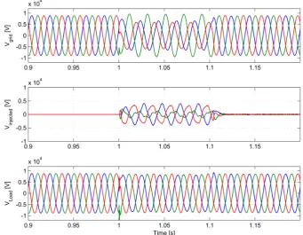
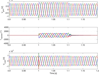
5.4.5. Case 4 and Case 5: Balanced and unbalanced voltage swells. 287
From the technical point of view, the DVR should mitigate voltage swells in the same way it 288
mitigates voltage sags. The detection technique is based on the difference between the magnitude 289
and phase angle of grid voltage and load voltage. The VSC generates the missing voltage through 290
the transformer for compensation. However, it is completely different from the viewpoint of the 291
energy handling capability. In the case of voltage sags, the DVR supplies an active power to the load 292
294
Figure 12. Case 4: Balanced voltage swell: grid voltage, injected voltage of the DVR and load voltage. 295
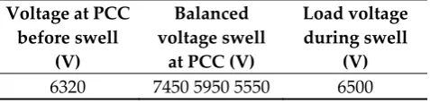
Table 1. RMS Voltage of Case 4- Balanced Voltage Swell. 296
Voltage at PCC before swell
(V)
Balanced voltage swell
at PCC (V)
Load voltage during swell
(V)
6320 7450 6580
297
In the case of balanced and unbalanced voltage swell, swell has occurred at 1,00 s of the 299
duration 0,1s. Figures 12 and 13 present the simulation results of the grid voltage, injected voltage 300
of the DVR and load voltage. The information on the voltage at PCC and load voltage is presented in 301
Tables 1 and 2. When voltage swell occurs, the grid voltage increased by 18%, the DVR compensates 302
so the load voltage increased below 4%. In such way the swell doesn't influence the operation of the 303
load. We can see, that the DVR has successfully maintained the load voltage is spite of balanced or 304
unbalanced swells. 305
Table 2. RMS Voltage of Case 5- Unbalanced Voltage Swell. 306
Voltage at PCC before swell
(V)
Balanced voltage swell
at PCC (V)
Load voltage during swell
(V)
6320 7450 5950 5550 6500
5.4.6. Case 6: Fluctuations and distortions of voltages 307
In this simulation, the fluctuations and distortions of voltages caused by switching on and off 308
the capacitor at HV side of the distribution transformer, were created for the duration of 1,0 s to 1,5 s. 309
310
The voltage waveform of grid voltage, injected voltage of the DVR and load voltage are shown 311
in Figure 14. The THD (Total Harmonic Distortion) of the voltage at PCC is 2.86% (measured for 10 312
cycles’ interval after switching on the capacitor) and decreased to 0.94% at load side. It can be 313
observed that the load side voltages are maintained and sinusoidal waveforms are kept almost 314
intact. 315
316
Figure14. Case 6- Fluctuations and distortions voltages: grid voltage, injected voltage of the DVR 317
and load voltage. 318
5. Conclusions 319
In this paper it was presented a DVR which can compensate balanced and unbalanced voltage 320
sags and swells and other utility voltage disturbances. The DVR is described in detail, configuration, 321
and its sag/swell detection voltage technique, grid synchronization techniques and control 322
technique. The simulation results under several conditions, balanced and unbalanced voltage sags 323
and swells, fluctuations and distortions are presented. The results demonstrate that the proposed 324
DVR is capable of compensating efficiently most of power quality problems, as well as harmonics in 325
the grid voltage. It provides fast dynamic response and has the advantage of simple structure and 326
high . 327
Conflicts of Interest: The authors declare no conflict of interest. The founding sponsors had no role in the 333
design of the study; in the collection, analyses, or interpretation of data; in the writing of the manuscript, and in 334
the decision to publish the results. 335
References 336
1. Shazly A., Mohammed Aurelio G., Cerrada Abdel-Moamen M. A and Hasanin B.. Dynamic Voltage 337
Restorer (DVR) System for Compensation of Voltage Sags State-of-the-Art Review. International 338
Journal of Computational Engineering Research (ijceronline.com) Vol. 3 Issue. 1. 339
2. Rakeshwri Pal, Dr. Sushma Gupta: State Of The Art: Dynamic Voltage Restorer for Power Quality 340
Improvement”. Electrical & Computer Engineering : An International Journal (ECIJ) Volume 4, Number 2, 341
June 2015. 342
3. Mahmoud A., El-Gammal Amr, Y. Abou-Ghazala and Tarek I. El-Shennawy. Dynamic Voltage 343
Restorer (DVR) for Voltage Sag Mitigation. International Journal on Electrical Engineering and Informatics 344
vol. 3 no. 1 2011. 345
4. Shazly A., Mohammed Aurelio G., Cerrada Abdel Moamen M. A., and Hasanin B.. Conventional 346
dynamic voltage restorer for mitigation of voltage sag in power distribution systems. International 347
Journal of Advances in Engineering & Technology (IJAET) Vol. 6 Issue 1 pp. 415-425 Mar. 2013. 348
5. Saeed S. A. M. Abdel Aleem H.E. Ibrahim A. M. Balci Essam M. E. El-Zahab E.A.. Power conditioning 349
using dynamic voltage restorers under different voltage sag types. Journal of Advanced Research. 2015, 350
vol. 7, iss. 1, pp. 95-103. 351
6. Resmi R. Reshmi V. and Jacob J. Mitigation of Voltage Sag Swell and Harmonics by Dynamic Voltage 352
Restorer using Matrix Converter. International Journal of Advanced Research in Electrical Electronics and 353
Instrumentation Engineering. Vol. 2 Issue-2 pp. 297-304 Dec. 2013. 354
7. Devaraju T. , Reddy V. C., Kumar M. Vijaya. Performance of DVR Under Different Voltage Sag And 355
Swell Conditions" ARPN Journal of Engineering and Applied Sciences Vol. 5 No. 10 October 2010. 356
8. Dung Vo Tien, Gono R., Leonowicz Z., Trinh Tran Duy, Martirano L. . Advanced Control of the 357
Dynamic Voltage Restorer for Mitigating Voltage Sags in Power Systems. Advances in Electrical and 358
Electronic Engineering. (article in press). 359
9. Bach Q. K., Lian J., Ramachandran B., Srivastava S., Cartes D.. Mitigating voltage sags due to DOL 360
starting of three phase asynchronous motors using dynamic voltage restorer (DVR). Proceedings of 361
IEEE PES Transmission and Distribution Conference and Exposition 2012. 7-10 May 2012. DOI: 362
10.1109/TDC.2012.6281673 363
10. Nguyen P. T., Tapan. K. Saha. Dynamic Voltage Restorer against Balanced and Unbalanced Voltage 364
Sags: Modelling and Simulation”. Proceedings of IEEE Power Engineering Society General Meeting, 365
vol. 1, pp. 639-644, June 2004 366
11. Bingsen Wang, Giri Venkataramanan and Mahesh Illindala. Operation and control of a dynamic 367
voltage restorer using transformer coupled H-bridge converters. IEEE Transactions on Power 368
Electronics, vol. 21 pp. 1053-1061 July 2006. 369
12. Fitzer M., Barnes P. Green. Voltage sag detection technique for a dynamic voltage restorer. 370
Proceedings of IEEE Industry Applications Conference. vol. 40 no. 1 pp. 203-212 Jan./Feb. 2004. 371
13. Trinh Tran Duy, Dung Vo Tien, Gono R. and Leonowicz Z. Mitigating Voltage Sags due to short 372
circuits using Dynamic Voltage Restorer. Proceedings of IEEE International Conference on 373
Environment and Electrical Engineering. Italy: EEEIC, 2016. pp. 2671-2676. 374
14. Dugan R.C., Granaghan M.F., Santoso S., Beaty H.W. Electrical Power Systems Quality. 2nd Edition, 375
McGraw Hill, 2004. 376
15. Bollen M. H. J. Understanding Power Quality Problems—Voltage Sags and Interruptions. Piscataway, New 377
York: IEEE Press, 2000 378
16. Teodorescu R., Liserre M. and Rodríguez P.. Grid Converters for Photovoltaic and Wind Power Systems. 379
17. Nielsen, J. G. Design and Control of a Dynamic Voltage Restorer. Aalborg University, Denmark 381
Publishers, 2002. ISBN 90-77017-83-6. 382
18. Tarjei Midtsund. Control of Power Electronic Converters in Distributed Power Generation Systems, 383