Article
1
Investigation into Forming Limits of Multi-Layer
2
Hybrid Sheets with different Materials in the Middle
3
Shichen Liu 1, Lihui Lang 2,*, Shiwei Guan 3, Seigei Alexandrov 4,5 and Yipan Zeng 6
4
1School of Mechanical Engineering and Automation, Beijing University of Aeronautics and Astronautics,
5
100191, Beijing; [email protected]
6
2School of Mechanical Engineering and Automation, Beijing University of Aeronautics and Astronautics,
7
100191, Beijing; [email protected]
8
3School of Mechanical Engineering and Automation, Beijing University of Aeronautics and Astronautics,
9
100191, Beijing; [email protected]
10
4School of Mechanical Engineering and Automation, Beijing University of Aeronautics and Astronautics,
11
100191, Beijing; [email protected]
12
5Institute for problems in Mechanics of the Russian Academy of Sciences, Moscow 119526, Russia;
13
14
6Chengdu Aircraft Manufacturing Company LTD, Qingyang District Chengdu, 610073, Sichuan;
15
16
* Correspondence: [email protected]; Tel.: +86 1082316821
17
Abstract: Fiber-metal laminates (FMLs) such as Kevlar reinforced aluminum laminate (ARALL),
18
Carbon reinforced aluminum laminate (CARALL), and Glass reinforced aluminum laminate
19
(GLARE) offer great potential for weight reduction applications in automobile and aerospace
20
construction. In order to investigate the feasibility for utilizing such materials in the form of
21
laminates, sheet hydro-bulging tests are studied under the condition of uniform blank holder force
22
for three-layered aluminum and aluminum-composite laminates using orthogonal carbon and
23
Kevlar as well as glass fiber in the middle. The experimental results validate the finite element
24
results and they exhibited that the forming limit of glass fiber in the middle is the highest among the
25
studied materials, while carbon fiber material performs the worst. Furthermore, the crack modes are
26
different for the three kinds of fiber materials investigated in the research. This study provides
27
fundamental guidance for the selection of multi-layer sheet materials in the future manufacturing
28
field.
29
Keywords: fiber-metal laminates (FMLs); multilayer sheet bulging; forming limits; numerical
30
simulation; crack modes
31
32
1. Introduction
33
Hybrid materials such as fiber metal laminates are being widely used in aerospace and
34
automobile industries to replace the conventional metals and alloys for additional weight reduction,
35
strength, and fuel economy [1]. Lightweight alloys, for instance, aluminum have lower fatigue
36
strength and damage tolerance whereas, the composite materials like carbon fibers or glass fibers
37
have a poor impact and residual strength. Such materials in the form of Fiber metal laminates
38
produce a synergistic effect and offer better fatigue resistance, mechanical as well as thermal
39
properties and improved environmental protection [2, 3, 4].Fiber Metal Laminate (FML),as its
40
name implies, is a type of metal materials comprising of a laminate of many thin metal layers
41
adhesive, bonded with the composite material layers [5, 6]. Some common commercially available
42
FMLs include ARALL (Kevlar Reinforced Aluminum Laminate), based on Kevlar fibers, GLARE
43
(Glass Reinforced Aluminum Laminate), based on high strength glass fibers and CARALL (Carbon
44
Reinforced Aluminum Laminate), based on carbon fibers etc. The advent of ARALL materials is
45
considered as the first generation fiber reinforced metal laminate aiming to make a great
46
contribution to the lightweight design and improved fatigue resistance of the aircraft. But due to the
47
great gap between thermal expansion coefficient of the Kevlar fiber and aluminum alloy, the great
48
residual stress during the solidifying and cooling process was produced which made it difficult for
49
the fabrication of large curvature components and thus restrain the applications in the aerospace and
50
aircraft field [7]. In order to solve the problems of big residual stress and poor formability, the
51
Fokker Company in Netherland developed the glass fiber-reinforced materials which substituted for
52
the Kevlar fiber in the middle. Excellent fatigue strength (three times of the Aluminum 2024) and
53
damage tolerance (increase one to two times compared with Aluminum 2024), superior impact
54
resistance (almost 86% higher than the Aluminum 2024 of the same thickness), greater potential for
55
weight loss (15% to 30% weight reduction than Aluminum 2024) determine the extensive application
56
prospect of the GLARE materials in the new generation of high technology manufacturing area [8,
57
9]. Carbon fiber materials, a new kind of high-strength fiber applied in the third generation of fiber
58
metal laminates which possess the outstanding mechanical properties still need to be further
59
research for the commercialized production. In fact, the existence of potential difference makes the
60
electrochemical corrosion occurs between the interlayers which seriously affected the fatigue
61
characteristics of the laminate materials [10, 11, 12].
62
In general, the traditional approach to measuring the relationship between stress and strain, as
63
well as the forming limits of the fiber metal laminate sheet, is the unidirectional tensile test of the
64
blank materials. For example, G.R. Rajkumar et al.[13] had investigated the effect of strain rate and
65
lay-up configuration on the tensile behavior of four combinations of fiber metal laminates. He found
66
that the tensile strength increased with the increasing strain rate and the strength were maximum for
67
carbon-based FML structures, minimum for glass-based FML and hybrid FML material lies between
68
them. Ankush P. et al.[14] had found from the tensile test of the glass fiber-reinforced metal
69
laminates that the lay-up sequence had no influence on the initial modulus of the FMLs, but the
70
ultimate strength and post-ultimate strength behavior were significantly affected by it, analyzed by
71
the numerical simulation and experimental phenomenon. However, this kind of method mainly
72
makes it deform on the laminate plane surface and prone to produce the phenomenon of instability.
73
In one hand, the tensile test restrains the total deformation that can be reached by the sheet material.
74
On the other hand, the necking effect and section distortion of the specimen induce the lateral stress
75
which leads to the inconsistent with the axial stress (
σ
1) and yield stress (σ
s),σ σ
1>
s. Moreover,76
the uneven distribution of
σ
1 along the specimen section causes relatively large errors if we still77
regard 1
=
P
A
σ
as the axial stress.78
In order to solve the above-mentioned problems, it has been widely used to apply hydraulic
79
bulging test to obtain the mechanical behavior of the sheet materials. Correia J P M et al.[15] adopted
80
the method of finite element modeling to conduct the electromagnetic sheet bulging test which has
81
the advantages of improved formability, high productivity and reduction in tooling cost. Wang Z et
82
al.[16] put forward the ductile fracture criterion to find the forming limits of aluminum alloy
6k21-T4 sheet by bulging process in both simulation and experimental tests. He Z et al. [17] has
84
studied the mechanical properties of tubular materials through analyzing the tube hydro-bulging
85
experiments and proved it more feasible in characterizing the deformation behavior under bi-axial
86
stress state. Wang Y et al.[18] presents the overlapped sheet hydraulic bulge test which can improve
87
the formability of low plasticity metal by controlling the force conditions and stress states of target
88
sheets. In our study, the same measurement method of the forming limits of the multilayer
89
composite sheet by the hydro-bulging test has been adopted to verify its formability.
90
2. Materials and Methods
91
2.1 Materials
92
The material of upper and lower layer of the 2/1 multilayer hybrid sheet is aluminum alloy
93
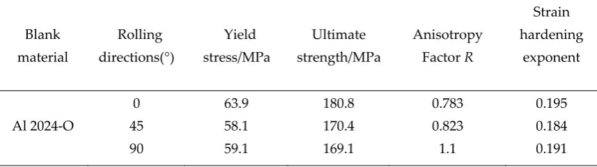
2024-O with the thickness of 0.4 mm. The material properties along the three main rolling directions
94
are shown in Table 1. In order to compare the formability of the multilayer sheet by measuring the
95
forming limits in the hydraulic bulging test, different cross-ply fibers including carbon, Kevlar and
96
glass(shown in Fig.1 ) as well as the same kind of aluminum alloy with uniform
97
thickness(
t
=
0.2
mm
) are carried out respectively. The blank size of the multilayer sheet is 150 mm98
× 150 mm and the method of constructing the composite laminate (apply the epoxy resin to the
99
fabric) is known as dry layup where the coefficient of contact friction is small. Elastic properties of
100
different material constituents in the laminate are shown in Table 2. The low plasticity of composite
101
material which can be neglected in the test varies greatly in the forming behavior of the aluminum
102
alloy 2024-O. Value of these parameters is consistent to make a good agreement on the experimental
103
results and finite element simulation analysis.
104
105
(a) Kevlar fiber (b) Carbon fiber (c) Glass fiber
106
Fig.1. Different kind of fiber materials in the middle used in the experimental test
107
Table 1. Material Parameter of Sheet Al 2024-O
108
Blank material
Rolling directions(°)
Yield stress/MPa
Ultimate strength/MPa
Anisotropy
Factor R
Strain hardening
exponent
Al 2024-O
0
45 90
63.9
58.1 59.1
180.8
170.4 169.1
0.783
0.823 1.1
0.195
0.184 0.191
Table 2. Elastic properties of different material constituents in the laminate
111
Material
Density (g cm/ 3)
1
E
(GPa)
2
E
(GPa)
ν
1212
G
(GPa)23
G
(GPa)13
G
(GPa)Al 2024-O 2.72 73.1 73.1 0.33 28.0 28.0 28.0
Carbon Fiber/Epoxy 1.76 232.0 8.61 0.28 3.75 2.30 2.30
Kevlar Fiber/Epoxy 1.44 85.3 5.5 0.4 2.54 0.97 0.97
Glass Fiber/Epoxy 2.52 53.98 9.412 0.23 3.50 2.06 2.06
112
2.2 Experiment
113
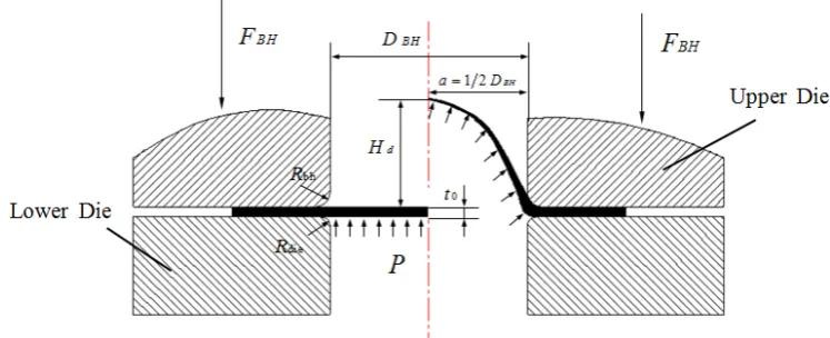
Fig.2 schematically illustrates the multilayer sheet hydraulic bulging test procedure researched
114
in the study. The flange of the external sheet is in contact with the lower die and necessary blank
115
holder force is provided by the upper die. The laminated blank gradually deforms with the increase
116
of the cavity bulging pressure affected on the bottom of the sheet. The hydraulic bulging equipment
117
is applied to test the forming limits of three kinds of fibers as well as the conventional aluminum
118
alloy in the middle and the diameter of the liquid chamber is 80 mm. The tests were conducted on
119
the self-developed 500KN sheet hydroforming machine at Beihang University which was controlled
120
by a hydraulic feed device connecting to the software installed in the computer shown in Fig.3.The
121
cavity pressure increases smoothly and stops immediately as the laminate cracks reaching its limits
122
during the bulging procedure. Values of the maximum cavity pressure and the limit bulging height
123
can be recorded immediately from the computer screen. Ultrasonic testing (UT) was utilized to
124
evaluate the wall thickness distribution in individual layers coupled with the limit bulging height
125
when the multilayer hybrid sheet fractures. Also, the friction coefficients between the interlayers
126
and testing moulds used in the finite element simulation analysis were measured by the friction
127
equipment detection machine MXD-02 following the ISO standard ASTM D1894.
128
129
130
Fig.2. Schematic diagram of multilayer sheet hydraulic bulging process
132
Fig.3. Multi-layer sheet hydro-bulging test machine
133
2.3 Finite element method model
134
Finite element analysis software ABAQUS/Explicit was used in measuring the forming limits of
135
the multilayer sheet. The numerical simulation model is represented in Fig.4 where the mold size
136
and process parameter are the same as the experimental test including liquid chamber cavity
137
dimension (80 mm) and the fixed blank holder force (20KN). Elastic and plastic properties of the
138
aluminum alloy, as well as the engineering constants and expansion factor of the composite fibers,
139
were imported into the material property module of the software. Also, the Hashin damage criterion
140
inside the software was used in predicting the initial fracture moments. Blank holder and the liquid
141
chamber were considered as discrete rigid with a mesh size of 5 and the laminate sheet set as a
142
4-node doubly curved shell with reduced integration was treated as deformable bodies meshing a
143
size of 4. Fiber orientation can also be established as cross-ply (0°/90°) direction in the finite element
144
simulation analysis. A friction coefficient of 0.05 was used for the interfaces between the outer metal
145
layer and the middle layer, and 0.12 for that between the upper metal sheet and the blank holder, 0.1
146
for that between the lower metal sheet and the liquid chamber, respectively.
147
148
149
Fig.3. Finite element method model of the three-layer sheet bulging process
150
3. Results and discussion
152
3.1 Maximum cavity pressure and limit bulging height
153
As can be seen from the experimental results, shown in Fig 4, that the crack phenomenon all
154
occurred around the curvature peak area where the laminate central region located and the forming
155
limits are measured to be different due to the various materials tested in the middle. During the
156
hydraulic bulging procedure, bulging height gradually raise as the increase in the pressure of the
157
fluid chamber and dropped immediately when the sheet laminate approaches the critical point of
158
instability which finally result in a large crack. The two index parameters (limit bulging height and
159
maximum cavity pressure) evaluating the forming limits measured by experiment and numerical
160
simulation are represented in Fig 5 and 6. Fig.5 indicates that the limit bulging height is 17.1 mm in
161
the experimental test when the aluminum sheet is used in the middle of the laminate. However, the
162
synergistic effects are diverse with different fibers substituting the metal sheet in the middle. As for
163
the Kevlar and glass fiber tested in the experiment, the limit bulging heights are 20.3 mm and 25.2
164
mm respectively, 18.7% and 47.4% improvement in formability. But the effect is negative for the
165
carbon fiber in the middle which measured only 15.8 mm height to the bulging limit, and the
166
reduction rate is about 7.6%. Similarly, the comparative relation is the same for the maximum cavity
167
pressure shown in Fig.6 in the hydro-bulging experiment. The maximum pressure effect by the fluid
168
chamber for the multilayered aluminum sheet is 13.8 MPa and the maximum cavity pressure
169
decrease to 12.6 MPa for the carbon fiber in the middle. It is also obvious to see that for Kevlar and
170
glass fiber replacing the aluminum alloy and carbon, the combined effects are positive with 14.3 MPa
171
and 17.8 MPa for the maximum cavity pressure, respectively. By comparing the results from the
172
above figures, it is easy to conclude that the forming limit for glass fiber in the middle of the
173
three-layer sheet is the highest which also demonstrate the formability is the best, followed by the
174
better forming behavior for Kevlar fiber, and the carbon fiber having inferior limit height coupled
175
with maximum pressure and formability among the four kinds of materials tested in the laminate
176
middle. Finite element simulation results reveal a high degree of consistence with the experimental
177
ones within reasonable errors.
178
179
180
Fig.4. Experimental results comparing different materials in the middle of the laminate:
181
(a) Aluminum sheet (b) Kevlar fiber (c) Glass fiber (d) Carbon fiber
Al / Al / Al Al / Kevlar / Al Al / Glass / Al Al / Carbon / Al 0
5 10 15 20 25 30
Lim
it
bul
gi
ng
hei
gh
t (
m
m
)
Multi-layer hybrid materials
Limit bulging height-Experiment Limit bulging height-Simulation
183
Fig.5. Limit bulging height of test laminates with different materials in the middle
184
Al / Al / Al Al / Kevlar / Al Al / Glass / Al Al / Carbon / Al
0 2 4 6 8 10 12 14 16 18 20 22
Maxi
mum
c
avi
ty
pre
ss
ure
(M
Pa
)
Multi-layer hybrid materials
Maximum cavity pressure-Experiment Maximum cavity pressure-Simulation
185
Fig.6. Maximum cavity pressure of test laminates with different materials in the middle
186
187
3.2 Stress-strain and wall thickness distribution
188
In order to study deeply on the forming limits and formability of the multilayer sheet especially
189
the materials in the middle, the paper works on the stress-strain and wall thickness distribution of
190
the tested materials at the instant of the crack phenomenon occurs. It is the fundamental analysis to
191
research on sheet deformation mechanisms which also provides an innovative judgment of the crack
192
modes for different fibers in the middle discussed in next section. In the finite element simulation
193
model, it can be regarded as the normal direction (0°) for the rolling direction of aluminum alloy and
194
also one of the principal orientations for the fiber materials. Fig.7 represents the stress distribution of
195
different materials in the middle along this direction (S11). The results indicate that the maximum
196
stress occurs at the central region which undergoes the maximum deformation for all the studied
materials and the variation of stresses differs significantly for the aluminum alloy and fiber materials
198
due to the differences between cross-ply composites and the approximately isotropic property of the
199
metals along rolling direction. It is also obvious to obtain from the stress distribution diagram that
200
the stress for the aluminum sheet in the middle is much higher than the fiber materials.
201
Nevertheless, the edge of the fiber materials produces a remarkable deformation in contrast to the
202
aluminum alloy on account of the limited plasticity of the above composite. For the different fiber
203
composites in the middle, although there is not much distinction in stress distribution, the details for
204
the comparison with the three fiber performance are well investigated. Carbon fiber in the middle
205
experience the maximum stress at the crack moment along the principal direction, glass fiber follows
206
and Kevlar fiber is the least among them. The reason why the stress distribution order is marked
207
distinguishing compared with the limit bulging height and maximum cavity pressure discussed in
208
the previous section is mainly due to the elastic properties especially the tensile modulus of the
209
fibers play the leading role in the whole bulging process. Even though the forming limit for the
210
carbon is the minimum among the studied fibers, the better capacity in elasticity makes the
211
maximum stress along the principal direction for the carbon the highest. Stress distribution of the
212
fiber materials in the middle, along the orientation perpendicular to the main direction (S22) is
213
almost the same due to the pattern of orthogonal layering.
214
Metal or alloys have much greater failure strain normally in the range of 10-50 % while
215
composite materials have quite limited formability as compared with the metals. The fibers fail at
216
much fewer strain values which are around 1% for carbon fibers, 2-2.5 % for Kevlar fibers and 4-5 %
217
for glass fibers. Numerical simulation result which measures the strain distributions of different
218
materials in the middle along radial and circumferential direction are shown in Fig.8. Zero
219
coordination position of the horizontal axis denotes the central location of the sheet and the
220
symmetrical characteristic makes it possible to plot the variation curve on one side. As can be seen,
221
the material performances have a great influence on the strain distribution of bulging specimen, the
222
radial strain for the aluminum sheet in the middle is much greater than composite fibers due to the
223
good plasticity which leads to the better flowability of the material. However, the maximal value of
224
225
(a) Aluminum sheet (b) Kevlar fiber
226
227
(c) Glass fiber (d) Carbon fiber
228
229
Fig.7. Stress distribution of different materials in the middle along the normal direction (S11)
strain and the distribution curve uniformity along the radial direction can be dramatically improved
231
by utilizing the glass fiber material as the middle layer when comparing the three composite fibers in
232
the study. This is caused by the failure strain of different fiber materials displayed above. Therefore,
233
with the selection of the glass fiber with greater failure strain and high strength, the reverse
234
compressive stress effected on the outer aluminum sheet increases and the three-dimensional stress
235
state enhances significantly. Also, the excessive local deformation of the multilayer sheet in the
236
central area is limited with decreased radial and circumferential strain and the fibers are easily
237
undergone the tensile failure during the bulging process even though the tensile modulus is not the
238
largest among them. Thus, the forming limits for the glass fiber are the best and the formability will
239
enhance greatly using this material. Wall thickness distributions of the materials in the middle
240
comparing experiment and finite element modeling results represented in Fig.9 are also a key factor
241
that influences the forming behavior of the sheet, particularly for the aluminum alloys. The picture
242
clearly demonstrates that there is almost no wall thickness reduction for the carbon fiber owing to
243
the lesser failure strain of such material, which results in the minimum bulging height at the same
244
time. But the aluminum sheet can bear more thickness reduction because of the unique material
245
mobility of the metals in comparison to the composite fibers. The maximum thinning rate in the test
246
can reach to 15.2 % while the value is 15.8% compared with numerical simulation results.
247
-10 0 10 20 30 40 50 60 70 80 0.00
0.02 0.04 0.06 0.08 0.10 0.12
Ra
di
al
s
tr
ain
Radius/mm
Aluminum sheet Kevlar fiber Glass fiber Carbon fiber
248
(a) Radial strain
249
-10 0 10 20 30 40 50 60 70 80 0.00
0.02 0.04 0.06 0.08 0.10 0.12
C
irc
umfere
ntia
l strai
n
Radius/mm
Aluminum sheet Kevlar fiber Glass fiber Carbon fiber
250
(b)Circumferential strain
251
Fig.8. Strain distribution of different materials along radial and circumferential direction
-10 0 10 20 30 40 50 60 70 80 90 0.165
0.170 0.175 0.180 0.185 0.190 0.195 0.200 0.205
Wall th
ick
ness (mm)
Radius/ mm
Aluminum sheet-Simulation Aluminum sheet-Experiment Kevlar fiber-Simulation Kevlar fiber-Experiment Glass fiber-Simulation Glass fiber-Experiment Carbon fiber-Simulation Carbon fiber-Experiment
253
Fig.9. Wall thickness distributions of different materials in the middle
254
3.3 Fracture criterion and crack modes
255
Fig.10 exhibits the geometrical profile of the crack bulging part using the aluminum sheet and
256
three kinds of fiber in the middle. Comparing the fracture mode of the metal and cross-ply fibers, it
257
is obvious to see that the three-layer aluminum sheet cracks along a certain orientation following the
258
rolling direction, but the multilayer blank fracture orthogonally (0°/90°) for the three fibers in the
259
middle on account of the pattern of orthogonal layering. To investigate more about the crack mode
260
of the fiber metal laminates, it is critical to judging the deformation of the outer aluminum layer and
261
middle layer which fracture first during the bulging process. Even though the experimental result
262
may be slightly hard to reflect the phenomenon and then measure the failure criterion, it is evident
263
to get the detailed conclusion from every reprocessing step in finite element modeling analysis.
264
According to the forming limit diagram (FLD) of the aluminum 2024-O and the failure strain of the
265
used fiber materials, the middle layer has been deduced to fracture first and the outer aluminum
266
layers fail at the same time even though they have not reached the forming limits. Fig. 11 reflects the
267
maximal thinning rate of the upper aluminum layer which undergoes the maximum deformation at
268
the initial moment of cracking. The result explains exactly why the glass fiber in the middle exhibits
269
the best formability while carbon fiber shows the worst forming limits. The lowest thickness
270
reduction of the outer layer at the instant of fracture demonstrates that the multilayer cracks quickly
271
without performing the outstanding elastic-plastic properties and excellent forming behavior of the
272
aluminum alloy when the carbon lay up in the middle. As for the glass fiber, the three-layer sheet
273
274
(a) Aluminum sheet (b) Kevlar fiber
276
(c) Glass fiber (d) Carbon fiber
277
Fig.10. Geometrical profile of the crack bulging part comparing four different materials in the
278
middle.
279
fails almost simultaneously with the metal and fiber material reaching the forming limits. This kind
280
of fracture modes provide a basic guidance for the future selection of fiber metal laminates and
281
prove that glass fiber in the middle which can also be called as GLARE materials have a wide
282
application in the manufacturing area.
283
Aluminum sheet Kevlar fiber Glass fiber Carbon fiber
7 8 9 10 11 12 13 14 15 16
M
axi
mum Th
in
ni
ng
rat
e
(%
)
Sheet materials in the middle Maximum Thinning rate-Experiment Maximum Thinning rate=Simulation
284
Fig.11. Maximum thinning rate of the upper aluminum layer at the instant of cracking
285
5. Conclusions
286
(1) Compared with the three-layer aluminum sheet hydro-bulging process, the fiber material
287
substituting in the middle have distinct influence on the forming limit measured by the limit
288
bulging height and maximum cavity pressure. Glass and Kevlar fiber used in the study is more
289
conducive to the improvement of multilayer sheet formability while carbon fiber has little or
290
even no impact.
291
(2) There is a big difference in stress-strain and wall thickness distribution of aluminum alloy and
292
different fiber materials in the middle of the multilayer sheet. Among the studied factors, failure
293
strain of the fibers as well as the thickness reduction rate of the aluminum sheet play a key role
294
in the formability of this kind of three-layer blank while the fracture mode which explains the
295
sequence of crack layers at the instant of fracture well validate the distinction between the
296
researched materials.
(3) For commercial-scale production, the formability of multilayer sheet can be greatly improved by
298
using the glass fiber in the middle. The relatively large forming limit and better formability of
299
the material in the hydro-bulging process makes it easy to form the specific part and the
300
comprehensive performance coupled with lightweight features illustrate the reason why the
301
GLARE materials have extensive applications in the aircraft manufacturing field.
302
303
Acknowledgments: The authors greatly acknowledge the financial support from National Science and
304
Technology Major Project with Grant No.2014ZX04002041 and National Science Foundation of China with
305
Grant No.51675029.
306
Conflicts of Interest: The authors declare that they have no conflict of interest.
307
References
308
1. Botelho, E.C. A review on the development and properties of continuous fiber/epoxy/aluminum hybrid
309
composites for aircraft structures. Materials Research, 2006; 9: 247-256
310
2. Vogelesang L.B; A. Vlot. Development of fibre metal laminates for advanced aerospace structures. Journal
311
of Materials Processing Technology, 2000; 103(1): 1-5
312
3. A.J.R Vermeeren. A Historical Overview of the Development of Fiber-metal Laminate. J Composite
313
Material, 2003; 10: 189-205
314
4. Asundi A; Choi AYN. Fiber metal laminates: An advanced material for future aircraft. J Mater Process
315
Tech, 1997; 63: 384-394
316
5. G. Reyes, H. Kang. Mechanical behavior of lightweight thermoplastic fiber–metal laminates. J Mater
317
Process Tech, 2007; 186: 284–290
318
6. Olga Sokolova; Adele Carrado; Heinz Palkowski. Metal–polymer–metal sandwiches with local metal
319
reinforcements: A study on formability by deep drawing and bending. Composite Structures, 2011; 94 : 1–7
320
7. Vogelesang, L.B; Gunnink, J.W. ARALL: A materials challenge for the next generation of aircraft. J. Mater.
321
Design, 1986; 7:287–300
322
8. Guocai Wu; J-M Yang. The Mechanical Behavior of GLARE Laminates for Aircraft Structures. J Failure in
323
Structural Materials, 2005;7:72-79
324
9. Sang Yoon Park; Won Jong Choi ;Heung Soap Choi .A comparative study on the properties of GLARE
325
laminates cured by autoclave and autoclave consolidation followed by oven postcuring. Int J Adv Manuf
326
Technol, 2010; 49:605-613
327
10. Yanagimoto J; Ikeuchi K. Sheet forming process of carbon fiber reinforced plastics for lightweight parts. J
328
CIRP Annals-Manufacturing Technol, 2012; 61 (1): 247-250
329
11. Dı́az, J. and L. Rubio. Developments to manufacture structural aeronautical parts in carbon fibre reinforced
330
thermoplastic materials. Journal of Materials Processing Technology, 2003; 43–144(0): 342-346
331
12. Hou, M; L. Ye; Y.W. Mai. Manufacturing process and mechanical properties of thermoplastic composite
332
components. Journal of Materials Processing Technology, 1997; 63(1–3): 334-338
333
13. G.R. Rajkumar; M. Krishna. Investigation of tensile and bending behavior of aluminum based hybrid fiber
334
metal laminates. Procedia Materials Science, 2014; 5:60-68
14. Aukush.P; Sanan H. Experimental and numerical investigation on the uniaxial tensile response and failure
336
of fiber metal laminates. Composites Part B, 2017; 125(15):259-274
337
15. Correia J P ; Ahzi S. Electromagnetic Sheet Bulging: Analysis of Process Parameters by FE Simulations.
338
Key Engineering Materials, 2013; 554: 741-748.
339
16. Wang Z J, Li Y. Evaluation of forming limit in viscous pressure forming of automobile aluminum alloy
340
6k21-T4 sheet.Trans Nonferrous Met Soc China, 2007; 17:1169-1174.
341
17. He Z B; Yuan S J. Analytical model for tube hydro-bulging tests, part II:Linear model for pole thickness
342
and its application. International Journal of Mechanical Science, 2014; 87 :307-315.
343
18. Yao Wang; Lihui Lang; Rizwan Zafar. Investigation into the overlapping sheet hydraulic bulge and its
344
formability. J Braz Soc.Mech.Sci.Eng , 2016; 38(6):1635-1645