166 | P a g e
AUTOMATIC GARBAGE TRACKING AND
COLLECTION SYSTEM
Aishwarya Ghongane
1, Aniket Piralkar
2, Vaishnavi Pawar
3,
Prof. Gaurav Narkhede
41,2,3
Electronics and Telecommunication, MIT college of Engineering, Maharashtra (India)
ABSTRACT
Automation is the Technology Concerned with Application of Mechanical, Electronics & Computer based
systems to operate & control production. Due to advancement in technology we have seen automization of many
things. Here we are tackling the issue for waste management and the first step towards it should be proper
collection of waste. And as this problem continues to increase day by day, we need to develop more efficient
management methods and techniques. Thus we are proposing an automated garbage collection system using
GSM module and also making use of Image Processing to improve the waste management.
In this system, a camera is placed near the garbage bin along with a load cell sensor under the bin. A threshold
value is set for the camera as it continuously takes the snapshots of the bin and also for the load cell sensor
which tells about the weight of the garbage. The microcontroller compares the value for camera and load cell
sensor and if the set threshold value gets exceeded then a message is sent through GSM to the control station.
The sent message will notify that the garbage bin is exceeding its capacity and needs urgent attention. Thus this
system can be a good help for the waste management issue.
Keywords: Electrode, GSM module, Image processing, Load cell, Webcam
I. INTRODUCTION
The automatic garbage tracking and collection system consists of a weighing system. The weighing system has
the function of the dynamic weighing within the loading scope of 1Kg, displaying the real loading by LCD and
sending the real weighing data to the monitoring client through GSM. Through the field test, the whole
weighing system performs well and reliable.
In present, we need to maintain the cleanliness of the society and this project helps us to do that with efficiency.
Here we are developing a system where the controller compares the value of the set point for the camera as well
as for the weighing sensor i.e. load cell and after analyzing the values, it will send SMS to the server giving
them the status of the garbage bins from time to time. Once the SMS is sent then the garbage collection centers
should look after it and take away the garbage. The electrode used here helps to distinguish the wet garbage
from the dry garbage. Thus we can also send a SMS regarding the occurrence of the wet garbage in the dry
garbage bin. The system overall will help us to maintain the spruceness of the environment with the help of
167 | P a g e
II. SCOPE
With the increasing need of automation in every field, we can make the best use of it by proposing a system for
garbage collection. By using the conventional methods, many cities are recognizing that those existing methods
and techniques are no longer effective. Thus, this type of system implementation should be used particularly in
new housing development projects.
With the use of Webcam in this system, we can use it for surveillance purpose as well. It is often instructed that
wet and dry garbage should not be mixed but people those who mix wet and dry garbage, can be filed a penalty
for mixing wet garbage in dry garbage can. This can be observed through webcam as it continuously monitors
the garbage can and surrounding.
III. LITERATURE SURVEY
As waste management operations all over the world attempt to become cleaner and greener in the face of new
legislation, some companies are looking to move away from the older systems of collecting and transporting
waste by road and are taking the whole thing underground.
Even though pneumatic waste collection systems have been around for decades, they are experiencing an
upsurge in popularity. As cities are becoming increasingly aware of the problems related to conventional
methods of waste collection. The trend to incorporate automated waste collection systems into new housing
development projects is rising, particularly in Europe, and in Asia where South Korea, Taiwan and Hong Kong
are leading the way in implementing this type of technology.
Users of the pneumatic waste collection system deposit their refuse into waste inlets, located around the chosen
operating area. Waste collection points are placed outdoors or indoors and are accessible 24 hours a day. There
is one waste inlet for each type of refuse (which will typically be divided into mixed waste, organic waste and
paper waste). The refuse is temporarily stored by the waste inlets until the next emptying cycle. The refuse is
then transported along the pipelines into containers at the waste station. When full, the containers are sent away
for further processing using, for example, the city’s existing underground railway network.
The system is remotely monitored and controlled by operators at the waste station. In addition, some staff is
needed to handle the system maintenance when required. No personnel are needed in the actual collection and
transport of waste from the collection point to the waste station. Typical application areas for pneumatic
collection systems include largemetropolitan and residential areas, high-rise buildings, public spaces, healthcare
facilities, and hotel and office complexes.
IV. PRESENT SCENARIO
Today garbage collection is a major problem. The information gathering is big and cumbersome thing. Today
the garbage collection is manual which takes a lot of efforts and is time consuming. In the Existing system
humans and vehicles are used to do that work and due to which it may sometimes prove as a health hazard to
human beings. People those who work in this garbage collection job are totally disappointed by the residents
168 | P a g e
bins for wet and dry garbage. But still people don’t even take the efforts for separation. Plastic bags are bannedto be used but still we can find dozens of plastic bags in the garbage containing waste food material etc. This has
to be stopped.
V. SYSTEM DEVELOPMENT
5.1. BLOCK DIAGRAM
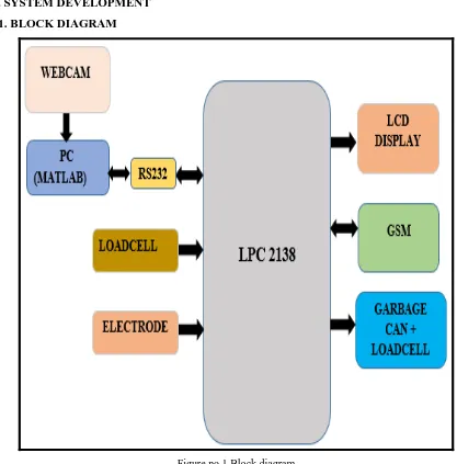
Figure no.1 Block diagram
Fig.1 shows block diagram of automatic garbage tracking and collection system. In this we have used ARM
7-LPC 2138 micro-controller to initiate all the operations through it. Load cell which is force sensor is used to
detect the weight of the garbage can. Certain threshold value will be set and when the weight exceeds this
threshold value a signal will be send to microcontroller through built-in ADC. Here we have used GSM module
which will send SMS to garbage collector station regarding over weighing of Can. LCD display is used to show
the status of the system. We have also used webcam which continuously monitors the garbage can and sends the
snapshots to the garbage collector station. Electrode is used to detect presence of wet garbage into dry garbage
can. Here we have used webcam which is interfaced to the controller through PC and RS 232. If the garbage can
169 | P a g e
has to be emptied and hence these snapshots taken through webcam will keep a track of this and it willcontinuously monitor the can and accordingly it will inform the control station regarding its status, whether
empty or full.This is done using image processing.
VI. HARDWARE DESCRIPTION
6.1
POWER SUPPLY
The basic step in the designing of any system is to design the power supply required for that system. The steps
involved in the designing of the power supply are as follows,
1) Determine the total current that the system sinks from the supply.
2) Determine the voltage rating required for the different components.
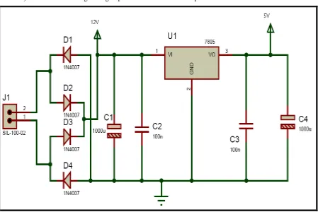
Figure no.2 Power supply circuit
The bridge rectifier and capacitor input filter produce an unregulated DC voltage which is applied at the input
of 7805.As the minimum dropout voltage is 2 V for IC 7805, the voltage applied at the input terminal should be
at least 7 volts.
C1 (1000 µf / 65v) is the filter capacitor and C2 and C3 (100nf) is to be connected across the regulator to
improve the transient response of the regulator. Assuming the drop out voltage to be 2 volts, the minimum DC
voltage across the capacitor C1 should be equal to 7 volts (at least).
6.2
Microcontroller
Here we have used LPC 2138 microcontroller as the basic building block of our system. It is used to process
170 | P a g e
loadcell about the weight of garbage can with the threshold level set and accordingly output signal is generated.It also measures the resistance change received from electrode. The LPC2138 microcontroller is based on a
16/32-bit ARM7TDMI-S CPU with real-time emulation and embedded trace support, that combine the
microcontroller with 512 kB of embedded high-speed flash memory.
6.3
Lcd Display
In the proposed system LCD display is used to display the messages like system initialization, garbage can full,
garbage can empty, wet garbage detected in dry garbage can etc. Microcontroller will continuously monitor the
status of the system and accordingly current status will be displayed on the LCD display. Here we are using
16x4 characters LCD.
6.4 Load Cell Sensor
A Load cell is a transducer that is used to convert a force into an electrical signal. This conversion is indirect
and happens in two stages. Through a mechanical arrangement, the force being sensed deforms a strain gauge.
The strain gauge measures the deformation (strain) as an electrical signal, because the strain changes the
effective electrical resistance of the wire. The electrical signal output is typically in the order of a few mill volts
and requires amplification by an instrumentation amplifier before it can be used. The output of the transducer
can be scaled to calculate the force applied to the transducer.
6.5 GSM Module
GSM (Global System for Mobile communication) is adigitalmobile telephony system. With the help of GSM
module interfaced, we can send short text messages to the required authorities as per the application. GSM
module works with a simcard provided by the mobile service provider and sends SMS to the respective
authorities as per programmed.
6.6
WEBCAM
A webcam is a video camera that feeds or streams its image in real time to or through a computer to computer
network. When "captured" by the computer, the video stream may be saved, viewed or sent on to other networks
via systems such as the internet, and email as an attachment. When sent to a remote location, the video stream
may be saved, viewed or on sent there. Unlike an IP camera (which connects using Ethernet or Wi-Fi), a
webcam is generally connected by a USB cable, or similar cable, or built into computer hardware, such as
laptops.
In our system, webcam is used to continuously monitor the garbage can. If garbage can is full but it has not
exceeded the threshold in that case snapshots taken from the webcam will alert the authorities at the garbage
dump station to collect the garbage and empty the can.
6.7
Electrode
An electrode is an electrical conductor used to make contact with a non metallic part of a circuit. Here electrode
is used to sense the presence of wet garbage in dry garbage can. In our system, we are using the concept of
171 | P a g e
between electrodes and an electrolyte or ionic species in solution. So when wet garbage is sensed by theelectrode chemical reaction occurs and it is informed by microcontroller regarding presence of wet garbage
VII. IMPLEMENTATION METHODOLOGY
Every society is provided with a garbage can with a unique id on it. This id will be stored in database with its
location. A webcam is mounted above each garbage can which is used for capturing images of garbage can
continuously. A database is maintained in PC of different set levels which is used to compare with the images
that are taken by the webcam. This is done with image processing. Webcam is interfaced with microcontroller
with the help of RS232 cable. At the same time load cell monitors the weight of garbage can. Load cell CZL601
is used. It will continuously sense the weight of garbage can. It is interfaced with microcontroller through ADC.
But as output of loadcell is in millivolts we have used instrumentation amplifier to amplify the output of loadcell
and then it is passed on to ADC. The microcontroller compares the output signal from ADC with the set
threshold voltage. If loadcell output crosses the threshold voltage then the GSM module interfaced to
microcontroller will send a message to server. This message consists of slave id of garbage can. The server
compares the received slave id and its location with the slave id’s of various garbage cans located in city stored
in its database. Then the server gives exact location of the garbage can which is full or over weighted to the
driver of waste disposal vehicle.
After receiving the message by the server the waste disposal vehicle reaches to the desired location and the
garbage can will be emptied in the waste disposal vehicle where the garbage is further recycled or disposed.
VIII. FLOWCHART
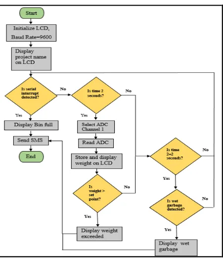
Fig.3 shows design flow of the system. In our system we have three conditions to be checked or performed.
These conditions are as follows:
1. Is Garbage Can weight exceeded the threshold point?
2. Is garbage can full without exceeding the threshold weight?
172 | P a g e
Figure no.3 FlowchartIX. CONCLUSION
The report features the prototype for an Automated Garbage Collection System using GSM Module and Image
Processing. The system helps to collect the garbage from the garbage bins on time before the garbage overflows
from that bin which can posses threat to the health of the people leaving in nearby area. The proposed system is
good enough to carry out practically as it has advantages such as having less time delays, quick response time,
fully automated system and also having low power requirement. It is robust system and thus can be used
efficiently. With the help of this system we can help to solve the problem of Waste Management by removing
173 | P a g e
REFERENCES
1.
Smart garbage collection system in residential area: International Journal of Research in Engineering and
Technology eISSN: 2319-1163 | pISSN: 2321-7308 Volume: 04 Issue: 03 | Mar-2015.
2. Arebey M.,Hannan, M.A. ; Basri, H. , Abdullah, H. “Solid waste monitoring and management using
RFID, GIS and GSM ”IEEE Student Conference on Research and Development (SCOReD), 2009.