capacity and performance of a structure, and a numerical analysis tool is a good back-up tool for making the experiment results more reliable in predicting the performance of the structure with various parameters. However, designers sometimes face practical problems such as experiment constraints, expenses, or realization of a real situation with scaled down models. This paper focuses on how to easily quantify the resistant capacity against overturning of submerged structures by experiment. The overturning resistance of a submerged structure in the experiment was acquired by an opposite concept in which a specimen was not placed on the bottom but dangled from the top. A numerical analysis was used to complement evaluation of the overturning moment. Overturning resistant capacity of submerged structures by waves was acquired easily from this method.
Index Terms—Overturning moment, substructure, offshore wind power, numerical analysis.
I. INTRODUCTION
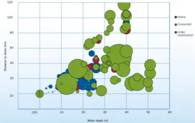
Environmental destruction has resulted in global warming and climate change problems which has inspired leaders of many countries to sign the “Paris Agreement” last year. In this context, offshore wind energy has been gaining more attention as a sustainable and environment-friendly energy resource. A lot of wind power systems were already installed on land and are generating electricity. A recent trend is that installation sites are shifting from land to the sea where better wind power is available. There are more obstructions to installing wind power systems in the sea than on land. However, engineers are overcoming these obstructions and challenges in going to sites that have deeper water as shown in Fig. 1 [1].
Design conditions get harsher as the water gets deeper and the farther it gets from the shore. Along with that, the substructures that support superstructures including rotor-nacelle assemblies, towers, and transition pieces need to be designed to stand against harsh environmental conditions. The transition pieces are made to connect two different forms and installed between substructures and the tower as shown in Fig. 2 [2].
In shallow water, substructures are mainly the mono-pile type. However, in deeper water, this type faces more obstructions, and the biggest is the construction cost as
Manuscript received February 15, 2016; received April 25, 2016. This work was supported in part by the Ministry of Trade, Industry & Energy of Republic of Korea.
Y. You, Y. Jeong, and M. Park are with the Korea Institute of Civil Engineering and Building Technology, Goyang, 10223 Republic of Korea (e-mail: [email protected], [email protected], [email protected]).
Fig. 1. Average water depth and distance to shore
Fig. 2. Transition piece.
Fig. 3. Cost of offshore wind turbine substructures with water depth.
II. TARGET SUBSTRUCTURES A. Hybrid Type
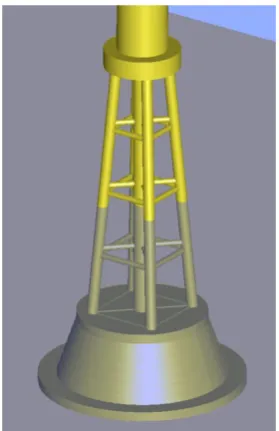
The hybrid substructure was designed to support 5.0 MW offshore wind power system. Geometry details of a turbine and tower were referred from [8]. Considered water depth was 20.0 m from the main sea level and the total height of the hybrid substructure was 37.5 m. The hybrid type has two parts. One is consisted of multi-piles and the other is a concrete base. The multi-piles and the concrete base play a role in decreasing wave force and increasing resistance for overturning, respectively. The lay-out and geometry of the hybrid type are shown in Fig. 4 and Fig. 5.
B. Gravity Type
In order to evaluate the resistant capacity of this hybrid type for overturning moment, there was a trial to find a structure of gravity type having similar capacity with the hybrid type. Unfortunately, there are little detailed information available. A research approach was considered in this study even though it was not yet applied to real site.
The gravity type substructure was referred from [9] and this was designed to support the 5.0 MW offshore wind power system same with the hybrid type. This substructure consisted of two parts with shapes of cone and cylinder as shown in Fig. 6. The gravity type had a height of 37.5 m.
Fig. 4. Lay-out of Hybrid substructure.
Fig. 5. Geometry of specimen (hybrid type).
Fig. 6. Geometry of specimen (gravity type).
C. Mono-pile Type
Geometry details of the mono-pile type was referred from [8] as shown in Fig. 7.
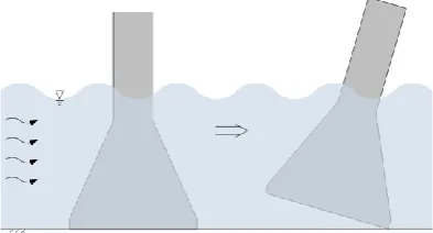
Fig. 8. Overturning of submerged structure by wave.
Fig. 9. Relationship between acting and reaction forces and positions.
In order to acquire the resistant capacity experimentally for overturning of a structure as in Fig. 8, pressure gages should be installed at the surface facing incoming waves and at the front and rear of the bottom of the structure. Gages installed at the surface facing incoming waves measure the pressure by the waves, and other gages installed at the bottom of the structure measure upright and downward pressure at the front and rear parts, respectively. However, it is not easy to measure the pressures at the front and rear of the bottom of the structure. The gages need to have sufficient capacity and durability to support the structure weight under water even before the waves are not present. Waves repeatedly approach the structure with crests and troughs. The wave crests and troughs can act as pushing and drawing forces on the structure. Hence, the front part puts more pressure on the gages installed underneath than whereas in still water The rear part of the bottom of the structure should be properly prevented from shifting by the waves and allowed for rotating. If the structure is rotated by the waves, the rear part would press the gage as an edge as shown in the right figure in Fig. 8. Moreover, the resistant capacity for overturning cannot not be measured if the structure has sufficient weight for the applied waves.
Considering that a body (self-weight is ignored) is on a hinge as shown in Fig. 9 (a) and a force acts on the body, the body will be inclined to the opposite direction of the force. At the moment, in order for the body not to be overturned, there should be a proper reaction force (R1) as shown in Fig. 9 (b). Consequently, a value of the reaction force times the arm
(4).
3 1 2 R l l
F (1)
4 2 1 R l l
F (2)
2 1 4 R l l
F (3)
2 1
2 4 3
1 R
l l l l
R (4)
B. Sketch of Experiment Frame
A jig to apply the concept to an experiment is shown in Fig. 10. The jig consists of a frame to support a specimen, a bar with circular cross-section, a bar to measure significant values, and hinges to allow the specimen to swing freely. The hinges have ball bearings. If there are no other restrictions, the specimen swings in response to the incoming waves.
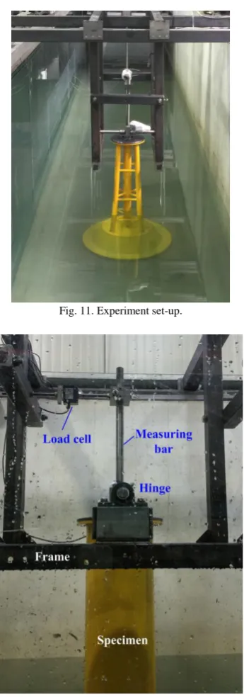
If a displacement gage is installed at the measuring bar with specific height from the hinges, a proportional displacement will be measured as the specimen swings. If a load cell is installed instead of a displacement gage, the specimen will not swing since a load cell does not allow displacement. A standing force of the specimen for incoming waves will be transferred proportionally through the measuring bar and the force will be measured by the load cell. Fig. 11 and Fig. 12 show experiment set-up and installed load cell, respectively.
C. Experiment Program
Specimens considered in this study were gravity and hybrid types..They were scaled down with 1/25 for size and 1/253 for prototype weight, respectively [10]. Geometry of specimens are shown Fig. 13 and their weight and specimen weight were 3,172 kg and 203 kg, respectively. A half of the cone part of the hybrid type was filled with water to calibrate the weight.
Fig. 10. Sketch of experiment jig.
Fig. 11. Experiment set-up.
Fig. 12. Installation of load cell.
(a)
(b)
(c)
Fig. 13. Geometry of specimens: (a) gravity type, (b) hybrid type, and (c) mono-pile type.
IV. ANALYSIS OF RESULTS
on a fixed vertical pile may be expressed as x I D D C u Du C
f
4 |
| 2
1 2
(5)
D
C = dimensionless drag coefficient
= density of sea water (t/m3) D= cylinder diameter (m)
u= water velocity amplitude (m/s) I
C = dimensionless inertia coefficient x
= water acceleration amplitude (m/s2)
The total horizontal force F exerted on that length of the pile ranging from y=0 (seabed) to y=y is given by the relation
yf ydy F
0 )
( (6)
Similarly, the total moment M about y=0 of the force exerted on that part of the pile from y=0 (seabed) to y=y is given by
yyf y dy M
0 )
( (7)
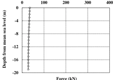
However, these relations may be used only for the mono-pile type in this study. Since the diameter of the gravity and hybrid types is changed along with the height, Eqs. (6) and (7) may not be applied. Even though pressure gages are installed on the specimens, it is not easy to acquire the wave force. From this reason, a numerical analysis too, AQWA, was used to acquire the force distribution and the centroid. The force distribution acquired by AQWA are shown in Figs. 14~16.
From these force distributions, a centroid where total force acts on the model was calculated and scaled down to adjust to the specimen. This value corresponds to l2 in Fig. 9 and
2 1 l
l becomes the height of the specimen. Therefore, the overturning moment can be acquired using Eq. (4). The results were tabulated in Table I.
Measured wave forces of the specimens were 38.8, 168.9, and 77.1 N for mono-pile, gravity, and hybrid types, respectively. For the same wave (real height and period were 3.435 m and 13.5 second, respectively), a less wave force acted on the newly designed hybrid type than that of the gravity type. A numerical analysis and the experiment results showed good agreement for the mono-pile type. This means that this experimental method with opposite set-up for real
-20 -16 -12 -8 -4 Depth fr om me an sea level ( Force (kN)
Fig. 14. Wave force on depth (Mono-pile type).
-20 -16 -12 -8 -4 0
0 100 200 300 400
Depth fr om me an sea level ( m) Force (kN)
Fig. 15. Wave force on depth (Gravity type).
-20 -16 -12 -8 -4 0
0 100 200 300 400
Depth fr om me an sea level ( m) Force (kN)
Fig. 16. Wave force on depth (Hybrid type).
TABLEI:COMPARISON OF MOMENT
Types Force * (N) Centroid** (m) Moment (kN-m) Cal. Num. Cal./Num.
Mono-pile 38.8 0.39 5,910 5,923 99.8% Gravity 168.9 0.28 18,474 21,053 87.8% Hybrid 77.1 0.18 5,272 7,427 71.0%
V. CONCLUSION
This study was performed to experimentally evaluate of the wave force. In this study, an experiment was performed with a special concept. This method worked successfully, and the wave force acting on the submerged structures was acquired through this method. Through this experiment, a result was deduced that, under the same environmental conditions, a newly designed hybrid type is less affected by the waves than a gravity type is. Moreover, a result from static analysis with wave force calculated by a generally used equation can help experiment performers predict the experiment result for measuring overturning moment of submerged structures.
ACKNOWLEDGMENT
This study was supported by the Ministry of Trade, Industry, and Energy of South Korea, Project No: 20123010020110 (Development of Hybrid Substructure System for Offshore Wind Farm), Project No: 20151120100140 (Air bubble barrier technology for preventing harmful substances accessing to the power plant intake), and by the Ministry of Oceans and Fisheries, Project No: 20120093 (Development of Concrete Substructure System and Design Guideline for Offshore Wind Farm).
REFERENCES
[1] EWEA, The European offshore wind industry - Key trends and statistics 2014, the European Wind Energy Association.
[2] Theguardian. [Online]. Available:
http://www.theguardian.com/environment/gallery/2011/aug/01/offsho re-windfarm-build-in-pictures
[3] NREL, “Energy from offshore wind,” National Renewable Energy Laboratory, 2006.
[4] EWEA, Deep water-the next step for offshore wind energy, Report, 2013. the European Wind Energy Association.
[5] F. Gerven, “Optimising the desing of a steel substructure for offshore wind turbines in deeper waters,” MSc thesis, TU Delft, 2011. [6] M. Park, Y. Jeong, and Y. You, “Structural analysis of a hybrid
substructure with multi-cylinder for 5MW offshore wind turbines,” in
Proc. the ASME 2014 33rd International Conference on Ocean, Offshore and Arctic Engineering, OMAE 2014, June 8-13, 2014. [7] J. M. Peeringa, Wave Loads on Offshore Wind Turbines,
ECN-C–04-042, 2004.
[8] J. G. Espinosa, Design and Calculus of the Foundation Structure of an Offshore Monopile Wind Turbine, University Politecnica de catalunya, Spain, 2012.
[9] MOF, Development of Design Basis and Concrete Technologies for Offshore Wind Turbine Support Structures, Report, Ministry of oceans and fisheries in the Republic of Korea, 2014.
[10] G. Yoshimi, Random Seas and Design of Maritime Structures, 3rd edition, World Scientific, 2010, p. 332.
[11] T. H. Dawson, Offshore Structural Engineering, Prentice-hall Inc., 1983.
Young-Jun You earned his Ph.D degree in civil engineering from Yonsei University, Seoul, Korea. He has been working for Korea Institute of Civil Engineering and Building Technology (KICT) in Gyeonggi-Do, Korea since 1998 and his current position is senior researcher. He participated in some projects for developing GFRP (Glass Fiber Reinforced Polymer) reinforcement for concrete structures and strengthening and rehabilitation of structures. He now studies on offshore support structures. Dr. You is a member of KSCE (Korean Society of Civil Engineers) and KCI (Korea Concrete Institute), especially was a former representative of KCI.
Youn-Ju Jeong earned his Ph.D degree in civil engineering from Yonsei University, Seoul, Korea. He has been working for Korea Institute of Civil Engineering and Building Technology (KICT) in Gyeonggi-Do, Korea since 1994 and his current position is research fellow. He participated in some projects for the offshore and marine structures. He now studies on offshore support structure. Dr. Jeong is a member of KSCE (Korean Society of Civil Engineers) and COSEIK (Computational Structural Engineering Institute of Korea).
Min-Su Park earned his Ph.D degree in system information engineering from Kagoshima University, Kagoshima, Japan. He has been working for Korea Institute of Civil Engineering and Building Technology (KICT) in Gyeonggi-Do, Korea since 2012 and his current position is senior researcher. He participated in some projects for the offshore structure and offshore renewable energy. He now studies on wave energy devices and substructure for offshore wind turbine. Dr. Park is a member of KSCE (Korean Society of Civil Engineers), KSOE (Korean Society of Ocean Engineers), SNAK (Society of Naval Architects of Korea) and KCI (Korea Concrete Institute).