Numerical Analysis of a Moving Object in the Air
Tunnel
Wanis Mustafa Edukali Shibani
#1, Mohd Fadhli Zulkafli
#2,
Bambang
Basuno
#3,
Abas Bin Ab Wahab
#4#
Department of Aeronautical Engineering, Universiti Tun Hussein Onn Malaysia 86400 Parit Raja, Johor, Malaysia
[email protected] 4 [email protected]
Abstract — This study highlights the influences of internal airflow on the motion of an object in an air tunnel to determine an alternative method of transporting goods from one place to another through such air tunnel. Flow analysis is performed using the FLUENT software version 16.1 to understand the movement of an object inside an air tunnel. The flow domain along the air tunnel is discretized using tetrahedron grids with the governing equation of fluid motion solved by employing the SIMPLE algorithm. Accordingly, the required turbulence modeling is provided by the turbulence model. The object is set to have a box shape with a rectangular wing attached on it. The air movement was created by the presence of a pressure difference between the flow condition at the inlet and outlet of the air tunnel. FLUENT produces the result that describes the movement of the object and flow pattern that appears inside the air tunnel. Result indicates the possibility of defining an object, which has a particular geometry to float and move when the air is moving through the air tunnel.
Index Term-- Numerical simulation, Aerodynamic, Internal flow field, Projectile
I. INTRODUCTION
The movement of goods and people from one place to another cannot be avoided in the lifestyle in modern society. Consequently, traffic jams often occur in various transportation routes. Such conditions could cause problems in delivering goods to shopping centers on time, particularly for goods that have short life times, such as vegetables, fruits, and fresh fish, among others.
A good transportation system is crucial to the rapid and efficient movement of goods and people from one place to another or from the factory to the shopping center. Currently, transportation systems commonly involve route transportation, such as the railway transportation system. Another transportation mechanism for goods that may be used is through an air tunnel. This approach does not interfere with existing railway or road vehicle systems. Thus, using an air tunnel will reduce route traffic jams and provide a rapid system for the delivery of goods to various destinations.
The present study investigates the movement of an object inside an air tunnel to determine whether the delivery of goods through this system can be accomplished. The motion of a solid body as a projectile through the air is one of the leading classical problems of applied mathematics that has baffled mathematicians, such as Galileo Galilei [1, pp. 244–294] and
John Edensor Littlewood [2, 3], for many years. A few individuals felt that the study of projectile motion was unsightly. For example, Hardy [4, p. 140] wrote that ballistics are “repulsively ugly and intolerably dull; even Littlewood could not make ballistics respectable.’’ Hackborn [5] wrote that his goal is to show that his study engenders beautiful and interesting mathematics.
“Ground effect” is the corroborative force performance of a lifting surface operating in close proximity to the ground. This phenomenon was first studied in 1920. In 1927, Konstantin Tsiolkovsky provided an example of a theoretical solution to the ground effect that was applied to an air cushion vehicle. Cui and Zhang [6] further explored the ground effect aerodynamics.
With the advancement in computational fluid dynamics (CFD), ground effect aerodynamics is mostly solved using the Reynolds-averaged Navier–Stokes (RANS) method with different turbulence models [7, 8, and 9]. The present study uses the turbulence modeling k − ε model for the required turbulent model in RANS. The k − ε model was first proposed by Launder and Spalding [10] and has been the focus of various improvements and modifications. Zhang and Wang [11] used this model to evaluate an underwater torpedo launch using the FLUENT–CFD software. This software uses an algorithm called the SIMPLE scheme to solve the RANS equation. Various numerical schemes exist, such as SIMPLEC, SIMPLER, SIMPLEST, CTSSIMPLE, and PISO, which represent the considerable development of the SIMPLE scheme [12, 13]. However, Sohankar et al. [14] proposed SIMPLE, which is a robust numerical scheme that has been extensively applied in many fields, either in research or in production.
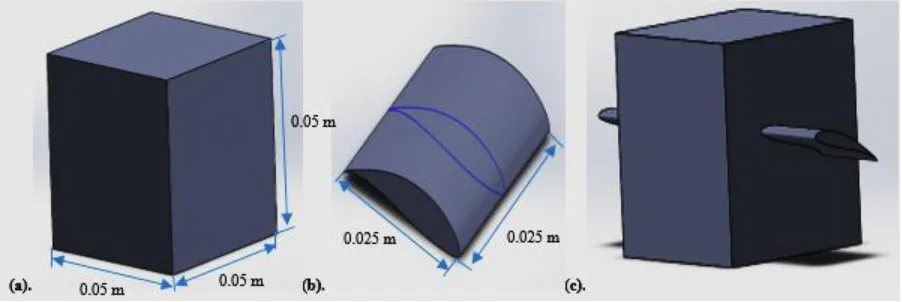
Fig. 1. Models (a) for a cube, (b) for the wing, and (c) for the object
Fig. 2 shows the air tunnel used in this study, which has a length of 5 m and diameter of 0.15 m.
Fig. 2. Dimensions of the 3D air tunnel
Fig. 3. The air tunnel (a) YZ plane, and (b) XY plane
III. MESH TOPOLOGY
The object was prepared using SOLIDWORKS software and imported into the ANSYS software thereafter. In this study, a non-uniform unstructured mesh was used with a considerably fine mesh implemented in regions of high gradients. A tetrahedron element was selected as the mesh of the object and air tunnel. A tetrahedral mesh is rarely used in
the wind engineering literature because of its lower efficiency of space discretization than the structured mesh. However, a tetrahedral mesh has the advantage of flexibility. The mesh layout of the cross-sectional plane is illustrated in Fig. 4. The total number of mesh elements reached 613181 tetrahedron
elements and 1206136 triangular interior faces
Fig. 4. Tetrahedral meshes around the model
IV. NUMERICALCALCULATIONMETHOD
ANSYS Fluent [17] is a commercial CFD software that was used to analyze the interaction of the object with the surrounding air inside the air tunnel. A six degree of freedom of the rigid body dynamics solver was incorporated into ANSYS Fluent to model the free flight of the object.
A. GOVERNING EQUATIONS
Considering that the problem deals with flow problems in which the flow speed is less than the Mach number M, which is equal to 0.3, the flow can be treated as an incompressible flow problem. In this flow phenomenon, the temperature variation over the flow field is nearly constant. Hence, the energy equation does not need to be solved.
The governing equation of the flow motion, which is an incompressible 3D flow known as the 3D incompressible Navier–Stokes equation, is written in a conservative form [18] and can be presented as follows:
Fig. 5. Boundary conditions of the air tunnel
V. CALCULATIONRESULTSANDANALYSIS
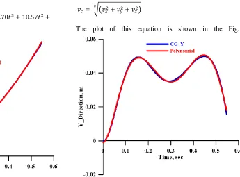
The movement of the object in time has been tracked based on the location of its center of gravity. The graphs presented in Figs. 6, 7, and 8 show that the locations of the object in the X-, Y-, and Z-directions, respectively, are plotted with respect to time. The movement of the object was determined to have a polynomial function in the following forms:
Thereafter, the X, Y, and Z velocity components are approximated using the derivative of these functions with respect to time. Hence, the velocity components of the object can be obtained as follows:
√( )
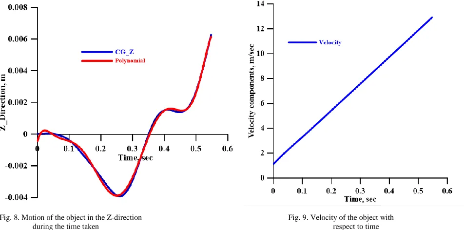
The plot of this equation is shown in the Fig. 9.
Fig. 6. Distance traveled by the object in the X-direction versus the Fig. 7. Motion of the object in the Y-direction
Fig. 8. Motion of the object in the Z-direction Fig. 9. Velocity of the object with
during the time taken respect to time
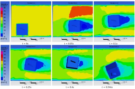
The flow pattern surrounding the object at different stations from the front view is shown in Fig. 10, while the side view is illustrated in Fig. 11. These two figures describe the flow conditions at time steps t = 0.0, 0.05, 0.1, 0.25, 0.4, and 0.546 s.
.
Fig. 11. Velocity contours for the flow field around the object in various positions in the X-direction, YX-plane
The center of gravity movement of the object in the XY-plane along the tunnel is shown in Fig. 12.
Fig. 12. Object trajectory with characteristic Squares
The results presented in Figs. 10, 11, and 12 provide the following descriptions.
- The object moves with a speed of 1.15 m/sec at the beginning of the motion at 0.001 s (Figs. 10 and 11) with respect to the horizontal line at 18°. At this setting,
FLUENT provides the result on the overall lift force work on the object, which is 2.13 N.
of attack of the incoming free stream with respect to the object is higher than the previous one. During this movement, the body rotates in a clockwise direction. - The result from FLUENT also indicates that at the time
step from t = 0.1 s to t = 0.2 s, the aptitude of the object is maintained. The object moves with speed varying from 3.30 m/s to 5.43 m/s.
- However, as time t progresses from t = 0.25 s to 0.3 s, the speed of the objects increases rapidly to achieve the speed of 7.58 m/s and make the object move to a distance of 1.27 m in the X-direction.
- Finally, when time t = 0.546 s, the object is nearly down to the bottom surface of the tunnel at 3.77 m in the X-direction.
These results indicate that moving or transporting an object through an air tunnel is possible. A longer distance can be achieved if the angle of the wing with respect to the horizontal line is adjustable to maintain the pitching moment works on the object at zero. That is, the object is floating with a lift that is equal to the object weight. Moreover, no rotation exists in this situation.
CONCLUSIONS
This study demonstrated the concept of goods transportation through an air tunnel using the aerodynamic forces created by the presence of the pressure difference between the flow condition at the inlet and outlet of the tunnel. Therefore, the transient motion of the object is affected by its orientation. Hence, the unstable behavior of the lift forces is induced. During the analysis, the lift force was observed to increase at the beginning of the motion and reached three times that of the weight of the object. The lift force also decreased in a few cases because of the loss of this force caused by high angles of attack relative to the flow. The distance covered in this simulation was 3.77 m, which is 75% of the total length of the air tunnel. Future studies should focus on achieving long distance movement by making the angle of the wing adjustable with respect to the horizontal line.
ACKNOWLEDGEMENTS
The authors would like to thank Universiti Tun Hussein Onn Malaysia (Grant Code: U416) for providing financial support for this research.
REFERENCES
1. G. Galilei, Dialogues Concerning Two New Sciences (Leyden, 1638), translated by H. Crew and A. de Silvio, Dover, New York, 1954. 2. J. E. Littlewood, Adventures in ballistics, 1915-1918, I, Math. Spectrum 4
(1971/72), 31-38.
3. J. E. Littlewood, Adventures in ballistics, 1915-1918, II, Math. Spectrum 4 (1971/72), 80-86.
4. G. H. Hardy, A Mathematician's Apology, Cambridge University Press, Cambridge, 1940, reprinted with a forward by C. P. Snow, 1967.
5. W. W. Hackborn, “MOTION THROUGH AIR: WHAT A DRAG,” vol.
14, no. 3, pp.285–298, 2006.
6. Cui, E. & Zhang, X. Chapter 18 Ground Effect Aerodynamics. (2010). 7. D. Lakehal and W. Rodi, “Calculation of the flow past a surface-mounted
cube with two-layer turbulence models,” Journal of Wind Engineering and Industrial Aerodynamics, vol. 67–68. pp. 65–78, 1997.
8. G. Iaccarino, A. Ooi, P. A. Durbin, and M. Behnia, “Reynolds averaged simulation of unsteady separated flow,” Int. J. Heat Fluid Flow, vol. 24, no. 2, pp. 147–156, 2003.
9. A. Yakhot, H. Liu, and N. Nikitin, “Turbulent flow around a wall-mounted cube: A direct numerical simulation,” Int. J. Heat Fluid Flow, vol. 27, no. 6, pp. 994–1009, 2006.
10.B.E. Launder, B.I. Sharma, Application of the energy dissipation model of turbulence to the calculation of flow near a spinning disk, Lett. Heat Mass Transfer 1 (1974) 131–138.
11.X. Zhang and S. Wang, “2D Axismmetric CFD Simulation of Underwater Torpedo Launch Tube Flow,” pp. 2–5, 2009.
12.Tao Wenquan. Numerical Heat Transfer, Xi’an, Xi’an Jiaotong University Press, Xi’an, 2001.
13.Zhang Zhaoshun. Turbulence. National Defence iIndustry Press, Beijing, 2003.
14.A. Sohankar, L. Davidson, and C. Norberg, “Numerical simulation of unsteady flow around a square two-dimensional cylinder,” p. 4, 1995. 15.M. Mashud, M. Ferdous, and S. H. Omee, “Effect of spoiler position on
aerodynamic characteristics of an airfoil,” Int. J. Mech. Mechatronics Eng., vol. 12, no. 6, pp. 1–6, 2012.
16.F. Kanyako and I. Janajreh, “Investigating Blade Performance of Small Horizontal Axis Wind Turbine based on Blade Element Momentum Theory,” pp. 85–90, 2013.
17.Fluent, “ANSYS FLUENT User’s Guide,” vol. 15317, no. November, p. 2498, 2011.