Plastic Buckling of Conical Shell with
non-Continuous Edge Support
O. Ifayefunmi
Faculty of Engineering Technology, Universiti Teknikal Malaysia Melaka, Hang Tuah Jaya, 76100 Durian Tunggal, Melaka, MALAYSIA
Abstract - The paper employs finite element analysis approach to examine the effect of local material discontinuities of a percentage of the hoop length of unstiffened cone subjected to axial compression or external pressure. It is assumed that the finite element models are made from mild steel with geometry given by r2/r1 = 2.02, r2/t = 34.3, h/r2 = 1.01, β = 26.56º and t = 2.89 mm. The material was modeled as elastic perfectly plastic. Numerical results were obtained for the case of axial compression only and external pressure only using ABAQUS finite element code for two different sets, and they are: (i) free edge support at one ends to the whole circumference (at top and/or bottom), and (ii) non-continuous edge support at the top and/or bottom edges which are applied to a fraction of the circumference. For cones with non-continuous edge support, results indicate that for both cases crack extending by 10% of the circumference of the cones will cause a drastic reduction in its buckling strength. For axially compressed cones, about 57% reduction in the load carrying capacity. Whilst, for externally pressurized cones, about 24% reduction in the collapse load. Also, it appears from both cases that crack extending by 20% of the circumference of the cone is enough to cause maximum reduction in its buckling strength. This is purely numerical study but references to accompanying experimental work are provided.
Index Term-- axial compression, external pressure, plastic buckling, unstiffened cones, material discontinuity, edge support.
I. INTRODUCTION
Thick cones are commonly used as structural components in marine and offshore structures. When in use, conical shells structures are subjected to different loading condition such as axial compression, external pressure, internal pressure and torsion. Of importance to the structural engineer is the safe performance of this conical shell structure during routine operation. Cones are prone to a number of imperfections, such as residual stresses, material inhomogeneity, imperfect length, load misalignment, non-uniform edge load distributions, initial geometric imperfections, non-uniform thickness distribution and influence of imperfect edge support. The presence of these imperfections can affect the load carrying capacity and the general safety of the conical shell structures. The most widely considered imperfection types are the initial geometric imperfection. Several investigations into the influence of
initial shape imperfections on buckling strength of conical shells can be found in [1 – 11]. However, very few studies have been reported on the influence of imperfect boundary condition on the load carrying capacity of cones. They can be found in [12 – 20]. In [12, 16, 20], the effect of the possible in-plane boundary conditions on the buckling behavior of conical shells subjected to external pressure was studied. For cones under axial compression, axisymmetric buckling can lead to lower buckling loads for certain boundary conditions (simply supported out-of-plane, varying in-plane restraint) as pointed out in Baruch et al., [13]. The severity of influence of radial edge displacement constraints on the limit load for thin stringer-stiffened conical shells subjected to axial compression was presented in [14]. Two cases were considered, namely: (i) radially fixed (SS-r) model and (ii) radially free (FF-r) model. It was shown that radial edge restrain has a strong effect on the limit load of the conical shell under axial compression. Also it was showed in [15, 19] that at a certain aspect ratio of unstiffened conical shell, different buckling mode correspond to the same value of critical buckling load.
Singer, [17], derived a method of analysis of the buckling of clamped conical shells under external pressure based on solution of modified Donnell-type stability equation. A similar effect was demonstrated experimentally by [18]. Numerical study into imperfection sensitivity of buckling loads for cones, taking imperfections in the form of eigenshapes and the effect of different boundary conditions on the load carrying capacity of the cones were examined by [21, 22]. In [21], cones with semiangle, β = 30, 55, 60, 65 and 70 for the case of axial compression only was investigated. Whereas in [22], eigenshape imperfection for cone with semiangle, β = 25.6 was considered for the cases of axial compression only, radial pressure only and combined loading, i.e., axial compression and external pressure acting simultaneously. The effect of different boundary condition (i.e., fully clamped, rotationally free, displacement free and displacement and rotation free) on the load carrying capacity of cone with semi-angle, β = 25.6 subjected to axial compression only and lateral external pressure only was also discussed.
approach to predict the buckling of unstiffened laminated composite cylinders and cones under various loading and boundary conditions. While [23] was devoted to linear buckling using the first order shear deformation theory, [24], on the other hand was concerned with the non-linear buckling behavior using a modified Newton-Raphson algorithm with line-search. In [25], the single perturbation load approach (SPLA) was used to examine the buckling behavior of geometrically imperfect composite cones under axial compression. Using this approach, a lateral load is applied prior to the axial compression, thereby stimulating a single dimple on the structure. Two types of imperfections were considered, they are: (i) mid-surface imperfection and (ii) thickness imperfections. References [26, 27] presented a semi-analytical approach based on Ritz method for calculating the linear buckling load of laminated composite cones under axial compression using the SS3 simply supported boundary condition using the First –order Shear Deformation Theory (FSDT) in conjunction with Donnell’s equation. It is evident, from literature survey, that there has been no information on the imperfection sensitivity of thick cones with non-continuous edge support Therefore, the present study concentrates on the effect of non-continuous edge support such as material discontinuity or crack on the load carrying capacity of thick cones subjected to axial compression only or external pressure only. In the present study, all analysis have been carried out using the general purpose finite element code
ABAQUS (Hibbitt et al. [28]). Frequent references are made toaccompanying experimental work presented in [29].
II. NUMERICAL APPROACH - BUCKLING OF AXIALLY COMPRESSED OR EXTERNALLY
PRESSURIZED CONES
The use of numerical model (mainly through finite element method) in studying shell buckling behavior has been successfully employed globally, [30]. In fact, it has been adjudge the most appropriate method for analyzing structural mechanics problems involving complicated behavior, such as buckling of cracked shells, material discontinuity at the edge support, effect of different boundary conditions etc.
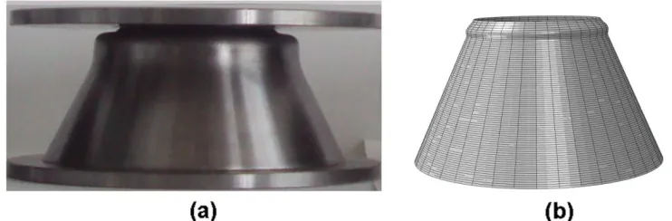
Therefore, the first step in this study was to set up an appropriate finite element model for the problem statement and benchmark its results with past experiments. Fig. 1a and 2a show views of collapsed cone subjected to axial compression and external pressure, respectively (see details in [29]). The corresponding finite element generated deformed shape are depicted in Fig. 1b and 2b, respectively. It is apparent from Fig. 1 and 2, that there is a good visual comparison of deformed geometry. In the case of axially compressed cone (Fig. 1), there is bulging out in the neighborhood of the small radius end of the cone. Whereas, for externally pressurized cone (Fig. 2), it was evident that both cones developed an inward lobes, n = 4 in the hoop direction.
Fig. 1.View of axially compressed cone – Fig. 1a and the FE generated shape – Fig.1b with bulging at the top end of the cone.
Fig. 2.View of externally pressurized cone – Fig. 2a and the FE generated shape – Fig.2b with the same number of lobes around the circumference.
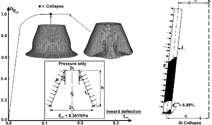
Typical load deflection curve for axially compressed cone and the corresponding spread of plastic strain distribution
through the shell wall thickness at collapse with r2/r1 = 2.02,
Similar response curve for the same cone subjected to lateral external pressure is shown in Fig. 4. For axially compressed cone, the largest plastic strain always appears at the outer surface of the small end of the cone. Whereas, for externally pressurized cone, the largest plastic strain always appears at
the inner part of the large end of the cone. It can be seen that there is no asymmetric bifurcation and the load carrying capacity in both cases is associated with axisymmetric collapse. And at collapse the wall undergo large plastic
straining with a plastic hinge developed.
Fig. 3.Plot of axial compressive force, F, against axial shortening for cones with r2/t = 34.3 with the corresponding collapse mode and spread of plastic strain at collapse.
III. SOLUTION METHODOLOGY – CONES WITH IMPERFECT EDGE SUPPORT
Consider a truncated cone with radii, r1 and r2, and uniform wall thickness, t, having the height, h, cone slant length, L
and semi-vertex angle, β, as sketched in Fig. 5a. Cones were assumed to be subjected to: (i) axial compression only (Fig. 5b) and (ii) external pressure only (Fig. 5c). Assume that the Finite element models are given by r2/r1 = 2.02, r2/t = 34.3, h/r2 = 1.01, β =
26.56º and t = 2.89 mm.
Fig. 5. Geometry of analysed cones (a) subjected to: (b) axial compression and (c) lateral external pressure.
The specimens were modeled using eight-node three-dimensional doubly curved shell elements with six degree of freedom (S8R in ABAQUS element library). Five integration points across the shell wall were used to estimate the spread of plastic strain along the shell wall. Non-linear static analysis was carried out using the modified Riks method algorithm, which is implemented in ABAQUS. Cones are assumed to be made from mild steel and the material were modeled as elastic perfectly plastic with E = 210.49 GPa, σyp = 230.6 MPa and υ
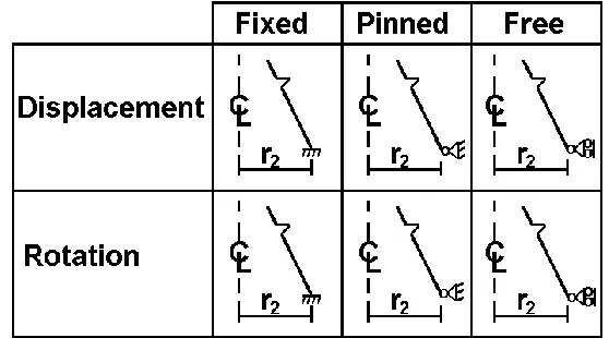
= 0.281 (see Ref. [29] for details). The boundary conditions employed are illustrated in Fig. 6. The fixed condition implies fully clamped, i.e., displacement and rotation degree of freedom are constrained (degree of freedom 1, 2, 3, 4, 5, 6 = 0). While, pinned condition implies displacement constrained
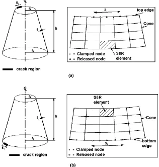
and rotation free (degree of freedom 1, 2, 3 = 0 and 4, 5, 6 0) and the free condition implies displacement and rotation degree of freedom are free (degree of freedom 1, 2, 3, 4, 5, 6 0). The FE grid obtained from convergence studies were used for both axial and hoop elements. Convergence study has shown that 143 (axial) x 40 (hoop) models were adequate for S8R modeling. In summary, the S8R model has 5720 elements and 22880 nodes. It was assumed that cones have local material discontinuities at the edge support such as crack over the limited hoop length as illustrated in Fig. 7. Whilst, Fig. 7a, illustrates non-continuous edge support at the top, Fig. 7b on the other hand depicts non-continuous edge support at the
bottom end of the cone.
Fig. 7. Illustration of the location of material discontinuity over the limited hoop length.
IV. RESULTS AND DISCUSSIONS
A. Influence of edge support on cones under axial compression or external pressure
This sub-section examines the buckling behavior of cones with radius-to-thickness ratio, r2/t of 34.3, having cone
semi vertex angle, β, ranging from 0º to 40º, and subjected to free edge support at one ends, i.e., displacement and rotation free for cones under axial compression or external pressure. It assumed initially that boundary conditions apply to the whole
circumference (at top and / or bottom).
TABLE I
Different edge support used for the FE calculations.
Edge Support/Boundary conditions
ux uy uz фx фy фz
Case (i) Top ≠0 ≠0 ≠0 ≠0 ≠0 ≠0
Bottom 0 0 0 0 0 0
Case (ii) Top 0 0 0 0 0 0
Bottom ≠0 ≠0 ≠0 ≠0 ≠0 ≠0
Case (iii)
Top 0 0 ≠0 0 0 0
Bottom 0 0 0 0 0 0
Top (si) ≠0 ≠0 ≠0 ≠0 ≠0 ≠0
Case (iv)
Top 0 0 0 0 0 0
Bottom 0 0 0 0 0 0
Bottom (si) ≠0 ≠0 ≠0 ≠0 ≠0 ≠0
Note: u ≡ displacements degree of freedom; ф ≡ rotation degree of freedom; (x, y, z, фx, фy, фz) ≡ global coordinate system.
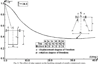
For cones under axial compression, the spread of plastic strains and initiation of buckling occurs at the upper end of the cone. Therefore it was decided to investigate the
support versus cone angle, β. It can be seen that as the cone angle increases, the failure load reduces under the influence of boundary condition. The reduction in failure load was about 64% of the collapse load for a fully clamped case for the worst
case (beta = 30 deg.). These results were consistent with our expectation and appeared to be very similar to those found for stiffened conical shell in compression observed by [14].
Fig. 8.The effect of edge support on the buckling strength of axially compressed cones.
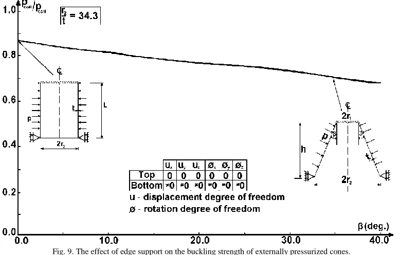
For cones under external pressure, contrary to cones under axial compression, plastic strains in externally pressurized cones, begin to spread at the lower end of the cone. Therefore, the upper end of the cone was fully clamped and the effects of free edge support at the lower end of the cone were examined – case (ii) of Table 1.
Results given in Fig. 9 shows a similar trends to that obtained for axially compressed cones, i.e., as the cone angle increases, the cone load carrying capacity reduces under the influence of boundary condition. Although, the loss of buckling strength is not as acute amounting to 34% of the
collapse load for a fully clamped case for the worst case (beta = 40 deg.). Thus, changing the edge support from clamped condition to totally free edge support at the lower end of the cone can cause significant reduction in the load carrying capacity of the conical shell under external pressure. This result is in agreement with suggestion by [17], stating that for cones with semi-vertex angle of 30 subjected to external pressure, clamped condition increases the buckling pressure of
Fig. 9. The effect of edge support on the buckling strength of externally pressurized cones.
B. Axially compressed cones with non-continuous edge support
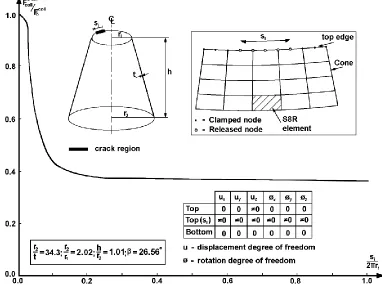
From Section 2, it has been observed that collapse/buckling of thick cones is mainly one of localized collapse, where the spread of plastic strain are localized within some region. Also, in practice the buckling/collapse strength of cones can be affected by the boundary conditions at the top/bottom edges which are applied to a fraction of the circumference. This could be caused by local material discontinuities such as crack over the limited hoop length. This sub-section examines the effect of local material discontinuities of a percentage of the hoop length of axially compressed cones. Axially compressed cones are clamped at bottom ends and allowed to move axially at the top ends, while all degree of freedom are free to move at the regions where material discontinuity is assumed to be present as described in case (iii) of Table 1. This is assumed to be more
realistic from the practical point of view since buckling/collapse initiation occurs at the top ends of the cone. The magnitude of material discontinuity, si, to the cone ends
circumference, si/2πr, was varied between 0.0 to 0.9.
Fig. 10 depicts the plot of buckling load corresponding to different imperfect models having a crack against increasing length of crack. It can be observed from Fig. 10 that crack extending by 10% of the circumference of the cones will cause a drastic reduction in its buckling strength, about 57% reduction in the load carrying capacity. Also, it appears from Fig. 10 for si/2πr ≥ 0.2, the line remains
Fig. 10. The effect of material discontinuities (crack) on the buckling strength of axially compressed cone.
C. Externally pressurized cones with non-continuous edge support
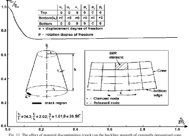
This sub-section examines the effect of local material discontinuities of a percentage of the hoop length of externally pressurized cones using similar approach to that of axially compressed cone in the preceding section. Externally pressurized cones are clamped at both the top and bottom ends and allowed to move in all degree of freedom at the regions where material discontinuity is assumed to be present as presented in case (iv) of Table 1. It was decided to locate material discontinuity at the bottom end of the cone because buckling/collapse initiation occurs at this location. The magnitude of material discontinuity, si, to the cone ends
circumference, si/2πr, was varied between 0.0 to 0.9.
Fig. 11 depicts the plots of buckling load corresponding to different imperfect models having a crack against increasing length of crack. A similar trend as observed for axially compressed cones was also seen here, i.e., crack extending by 10% of the circumference of the cones will cause a considerable reduction of about 24% in its buckling strength. It must be highlighted that this is not so severe as compared to its axially compressed counterpart. Also, it appears from Fig. 11 that for si/2πr ≥ 0.2, the line remains linear i.e., a fraction of
0.2 crack on the circumference of the cones is enough to cause maximum reduction in its buckling strength. Furthermore, it can be noticed that increasing the local material discontinuity
Fig. 11. The effect of material discontinuities (crack) on the buckling strength of externally pressurized cone.
V. CONCLUSION
Several conclusions can be drawn from numerical results obtained in this paper. It has been seen that the buckling strength of considered cones is affected by imperfect edge support. Results of the sensitivity of buckling strength when the end conditions are free around the full length of circumference shows that as the cone angle increases, the failure load reduces under the influence of boundary condition. The effect of small material discontinuities/cracks has shown to have a significant effect on the buckling strength of cones. Cones under axial compression are more sensitive to this type of defects when compared to cones subjected to external pressure. For crack extending by 10% of the circumference of the cones will cause a drastic reduction in its buckling strength, (about 57% - axial compression and about 24% - external pressure) reduction in the load carrying capacity. Whilst, crack extending by 20% of the circumference of the cones is enough to cause maximum reduction in its buckling strength (about 62% - axial compression and about 28% - external pressure).
REFERENCES
[1] Blachut J (2013), “Combined stability of geometrically imperfect conical shells”, Thin-Walled Structures,67, 121 - 128.
[2] Błachut J, Stanier D (2012), “Elastic buckling of conical shells under combined loading of axial compression and external pressure”, Proceedings of the Eleventh International Conference on Computational Structures Technology, B.H.V. Topping, ed., Civil-Comp Press, Stirlingshire, UK, Paper No. 163.
[3] Chryssanthopoulos MK, Poggi C, Spagnoli A (1998), “Buckling design of conical shells based on validated numerical models”, Thin-Walled Structures, 31, 257 – 270.
[4] Goldfeld Y (2007), “Imperfection sensitivity of laminated conical shells”, International Journal of Solids and Structures, 44, 1221 - 1241.
[5] Goldfeld Y, Sheinman I, Baruch M (2003), “Imperfection sensitivity of conical shells”, AIAA Journal, 41, 517 - 524. [6] Ifayefunmi O, Blachut J (2013), “Instabilities in imperfect thick
cones subjected to axial compression and external pressure”, Marine Structures, 33, 297 - 307.
[7] Jabareen M, Sheinman I (2006), “Postbuckling analysis of geometrically imperfect conical Shells”, ASCE Journal of Engineering Mechanics, 132, 1326 - 1334.
[8] Jabareen M, Sheinman I (2009), “Stability of imperfect stiffened conical shells”, International Journal of Solids and Structures, 46, 2111 - 2125.
[9] Zhang GQ (1993), “Stability analysis of anisotropic conical shells”, Ph.D. Dissertation, Delft University of Technology, Delft University Press, Delft, The Netherlands.
[10] Zhang GQ, Arbocz J (1993), “Initial postbuckling analysis of anisotropic conical shells”, 34th AIAA/ASME/ASCE/AHS/ASC Structures, Structural Dynamics and Materials Conference, USA, pp. 326-335.
[11] Zielnica J (2002), “Imperfection sensitivity and stability of an elastic-plastic conical shell under axisymmetrical load”, Archive of Applied Mechanics, 72, 395-417.
[12] Baruch M, Harari O, Singer J (1967), “Effect of in-plane boundary conditions on the stability of conical shells under hydrostatic pressure”, Proceeding of the 9th Israel Annual Conference on Aviation and Astronautics, Israel Journal of Technology, 5, 12-24. [13] Baruch M, Harari O, Singer J (1970), “Low buckling loads of axially compressed conical Shells”, Journal of Applied Mechanics, Transactions of the ASME,37, 384-392.
[14] Chryssanthopoulos MK, Spagnoli A (1997), “The influence of radial edge constraint on the stability of stiffened conical shells in compression”, Thin-Walled Structures, 27, 147 - 163.
[15] Pariatmono N, Chryssanthopoulos MK (1995), “Asymmetric elastic buckling of axially compressed conical shells with various end conditions”, AIAA Journal, 33, 2218 - 2227.
[16] Singer J (1962), “The effect of axial constraint on the instability of thin conical shells under external pressure”, Journal of Applied Mechanics, Transactions of the ASME, 29, 212 - 214.
[18] Singer J, Eckstein A (1963), “Recent experimental studies of buckling of conical shells under torsion and external pressure”, Proceedings of the fifth Israel Conference on Aviation and Astronautics, Jerusalem Academic Press, pp. 135-146.
[19] Spagnoli A (2003), “Koiter circles in the buckling of axially compressed conical shells”, International Journal of Solids and Structures, 40, 6095-6109.
[20] Thurston GA (1965), “Effect of boundary conditions on the buckling of conical shells under hydrostatic pressure”, Journal of Applied Mechanics, Transactions of the ASME, 32, 208 - 209. [21] Wunderlich W, Albertin U, 2000, “Analysis and load carrying
behaviour of imperfection sensitive shells,” Int. J. Numer. Methods Eng., 47, pp. 255–273.
[22] Ifayefunmi O, Blachut J (2011), “The effect of shape, thickness and boundary imperfections on plastic buckling of cones”, Proceedings of the ASME 2011 30th International Conference of Ocean, Offshore and Arctic Engineering (OMAE 2011), Vol. 2, OMAE2011-49055, pp. 23 - 33.
[23] Castro SGP, Mittelstedt C, Monteiro FAC, Arbelo MA, Ziegmann G, Degenhardt R (2014), “Linear buckling prediction of unstiffened laminated composite cylinders and conesunder various loading and boundary conditions usingsemi-analytical models”, Composite Structures, 118, 303 – 315.
[24] Castro SGP, Mittelstedt C, Monteiro FAC, Degenhardt R, Ziegmann G (2015), “Evaluation of non-linear buckling loads of geometrically imperfect composite cylinders and cones with the Ritz method”, Composite Structures, 122, 284 – 299.
[25] Khakimova R, Warren CJ, Zimmermann R, Castro SGP, Arbelo MA, Degenhardt R (2014), “The single perturbation load approach applied to imperfection sensitive conical composite structures”, Thin-Walled Structures, 84, 369 – 377.
[26] Shadmehri F (2012), “Buckling of laminated composite conical shells; theory and experiment”, Ph.D. Dissertation, Concordia University, Montreal, Quebec, Canada.
[27] Shadmehri F, Hoa SV, Hojjati M (2012), “Buckling of conical composite shells”, Composite Structures, 94, 787 – 792.
[28] Hibbitt, Karlsson and Sorensen (2006), ABAQUS-Theory and Standard User's Manual, Version 6.4, Pawtucket, USA. [29] Błachut J, Ifayefunmi O (2010), “Plastic buckling of conical
shells”, Journal of Offshore Mechanics and Arctic Engineering, Transactions of the ASME, 132, 1- 041401-11.
[30] Bushnell D (1985), Computerized Buckling Analysis of Shells, Dordrecht, Martinus Nihjoff Publishers.
AUTHORPROFILE