Abstract—Composite interface damage model is used to simulate cementitious composites and calculated with explicit algorithms and unit optimization. The simulation is established in the Ansys / Ls-dyna. Composite interface damage model is extended to the 3D .Failure process of macro dynamic compression in meso-scale was simulated. The Deformation and impact failure process of cementitious composites was built in SHPB experimental device. The influence of strain rate effect on the strength of cementitious composites was completed. The crack propagation was simulated, and the dynamic strength values DIF and other growth factors results were obtained.
Index Terms—Cementitious composites, 3D dynamic, meso-scale damage, numerical simulation.
I. INTRODUCTION
In the study of mecromechanics problem in cementitious composites, currently most are 2D static and dynamic tests. But with the development of mecromechanics, the numerical simulation of 3D dynamic meso-scale mechanical properties of cementitious composites could be achieved. This study based on composite interface damage model, which showed discontinuity, heterogeneity, anisotropy. Extended it to 3D, studied the process and destruction of dynamic impact of cementitious composites, and do the similar experiment.
With experiments and numerical simulations, the impact assessment of the overall strain rate effect on the mechanical properties of the cementitious composites is analyzed. Using the composite interface damage model, 3D analysis of cementitious composites dynamic compression failure process is showed and analyzed. In this paper, the Matlab and Ansys / Ls-dyna are combined to establish composite interface damage model. And use explicit algorithms and unit optimization to make the computation efficiencies. The failure process under macro-dynamic compression is in studied meso-scale, and given the simulation of crack propagation, intensity values, and issues such as dynamic growth factor DIF
II. MICROSCOPICDESCRIPTIONOFCEMENTITIOUS
COMPOSITEMATERIALS
A. DamageConstitutiveEquations
In the constitutive model, meso-scale units use the following assumptions: (1) cementitious composites, in the case only being effected by the tensile force, the constitutive
Manuscript received July 30, 2018; revised December 28, 2018. Fan Wang is with the School of Mechanics and Construction Engineering, Jinan University, China.
Chuanguo Zhong is with the Guangzhou Building Materials Institute Limited Company, China (e-mail: [email protected])
equation is considered brittle meso units, unit destruction is caused by the maximum tensile or maximum tensile stress; (2) when the cementitious composites is subjected to compressive load , the constitutive form of cementitious composites meso unit is bilinear damage, meso units is damaged by the maximum shear stress or maximum tensile stress. Fracture mechanics to describe the process of the destruction of the material is usually given in the material constitutive model and damage evolution equation.
E
(
1
D
)
(1-1)This equation describes the one-dimensional problem constitutive relation in material damage mechanics.
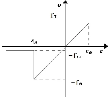
Damage meso unit is mainly caused by tensile and shear damage, and damage constitutive used in this paper was showed in Fig. 1. The relationship can be obtained in accordance with the figure uniaxial tensile damage factor expression case:
0 t
0 t
1
0
D
(1-2)
In the case of uniaxial compression, assume that the destruction of material to be bilinear forms, and materials have residual stressesfcr. Compression injury factor formula
is described in 1-3.
Fig. 1. Tensile and compressive stress-strain relationship.
In the compressed state, the maximum shear stress theory is selected as a second injury criterion, when the maximum shear stress is equal to the uniaxial compressive strength greater than two-thirds temporary injury.
Dynamic Analysis of Cementitious Composites
cu cuD
1
1
0
0 c 0 c 0 c (1-3) 00
f
e/
E
c
(1-4)
c cr
f
f
(1-5)
is the residual strength factor. Herein ultimate straincu
is times of
c0.B. WeibullDistribution
In random mechanics, it is used with a numerical model to describe the Weibull distribution parameters of random mechanics, meso-scale numerical simulation of cementitious composites is conduct in ANSYS / LS-DYNA.
x,
, m is Weibull distribution parameters, respectively, x: control the elastic modulus and strength, m: mean value, influence dispersion curve,
: the average value of the size of the impact curve.Since the meso-scale simulation assumes cementitious composites to be 3 phase materials, the Weibull parameters for each material selection problems should be studied. Tang chun, Wan-cheng take m and the selection problem a lot of research to obtain the elastic modulus and get the strength parameters m and theselected value variation [1].
Curve fitting is obtained:
) 50 2 . 1 ( 6476 . 0 ln 1412 . 0 / ) 50 2 . 1 ( 0233 . 0 ln 2602 . 0 / 0 0 m m E E m m f f s S cs
cs (1-8)
0
cs
f
and
E
s0 is selected Weibull strength distribution and the mean modulus of elasticity,f
cs andE
s is theintensity value of the sample, the elastic modulus
Fig. 2 uses a regular square mesh. As a result of the anisotropic material element in this article, in the rectangle is easier to achieve performance controlling material parameters, so a rectangular mesh approach in this article.
(a) (b)
Fig. 2. Meso structure. (a) Meso Structure and square mesh (b) Embedded interface unit.
C.Composite Interface Unit
In meso-scale simulation, in order to reflect the interfacial transition zone (ITZ) (thickness is about 0.01mm-0.1mm)
geometrical characteristics and material properties at the interface more detailed requirements, which will bring extremely difficult to calculate. So in this paper, ITZ will be considered a broad composite unit with composite theoretical rules [2]. The thickness of the article assumes that the ITZ is considered 0.1mm in this paper.
The Voigt-Reuss modified model assumes that the direction of the strain state of the cell is uniform x1, x2 direction and the state of stress is also uniform. Average stress and strain relations with each phase of the stress and strain is shown in Equation (1-9) to (1-19).
Fig. 3. Meso unit.
m 11 11 a 11
11
i
(1-1) m 22 22 a 22
22
i
(1-2) m 12 12 a 12
12
i
(1-3) m 11 i 11 a 11
11
a i ml
l
l
(1-4)m m i a
l
l
l
22a 22i 2222
(1-5) m 12 i 12 a 1212
a i ml
l
l
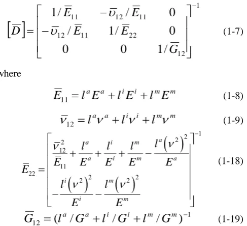
(1-6)Units of each phase are linear elastic isotropic material, combined with their constitutive relations, which is
D
,
D
is embedded interface unit elasticitymatrix, can be expressed as:
1 12 22 11 12 11 12 11/
1
0
0
0
/
1
/
0
/
/
1
G
E
E
E
E
D
(1-7) where m m i i a aE
l
E
l
E
l
E
11
(1-8)m m i i a a
l
l
l
12
(1-9)
1 2 2 2 12 11 22 2 2 2 2 aa i m
a i m a
i m
i m
l
l
l
l
E
E
E
E
E
E
l
l
E
E
(1-18) 112
(
/
/
/
)
a a i i m mG
l
G
l
G
l
G
(1-19)simplify the calculation process, interface unit is considered with the composites model formula, the formula can be elastic constants: m m i i a a
E
V
E
V
E
V
E
E
11
33
(1-1)1 22
aa ii mmE
V
E
V
E
V
E
(1-2)m m i i a a
V
V
V
2
(1-3)2 11 22 3
1
E
E
(1-4)1 23
12
(
/
/
/
)
a a i i m mG
V
G
V
G
V
G
G
(1-5)m m i i a a
G
V
G
V
G
V
G
13
(1-6)m i a
V
V
V
、
、
: the volume fraction of the aggregate, thevolume fraction of the ITZ, the volume fraction of mortar matrix.
D. ImplementedinANSYS / LS-DYNA
The materials used for the * MAT_COMPOSITE_ DAMAGE, the composite material constitutive model of injury, which could be defined in different directions elastic modulus relationships, which needs to define the following parameters: 1) RO: density; 2) EX, EY, EZ: elasticity in 3 directions modulus ; 3) VXY, VYZ, VZX: Poisson's ratio in 3 directions; 4) GXY, GYZ, GXZ: Cut modulus; 5) SC: shear strength; 6) XT, YT, x, y: direction tensile strength; 7) YC, y: direction compressive strength.
E. NumericalSimulation of 3D Meso-scale Dynamics of Cementitious Composite Materials
Due to the computational efficiency, there are less studies of 3D simulation of cementitious composite material than 2D, and most 3D analysis only stay in static simulation. In this paper, 3D composite interface damage model is used for cementitious composite simulation, analysis the mechanical properties of dynamic compression.
III. DYNAMICCOMPRESSIONSIMULATION
Dynamic compression process in split Hopkinson pressure bar (SHPB), its structure is carried out in Fig. 3-4. SHPB experimental apparatus is the basic means of dynamic mechanical properties of experimental studies of engineering materials, generally used to study the impact of problems in the strain rate range 1 ~ 100s-1, the paper used for the 74mm variable cross-section dimensions SHPB.
This article uses the two-wave treatment formula [3], [4] to reconstruct the stress-strain curves of concrete.
Fig. 4. SHPB device
A. AggregateGeneration
Generate aggregate basic steps are refer to paper 4 and 7, and diameter of aggregate is 5mm-15mm.Changes in the scope of the number of edges in both directions of ellipsoid are 3-10 edges [5-9]. Figure 5 are obtained using different parameters aggregate.
Fig. 5. Random variables aggregate.
B. HomogenizationandFreeMeshingProcessis DynamicCompression
It is generally considered that structural characteristics and physical properties of higher scales could be explained by lower scales [2 5], This chapter ignored the effect of strain rate on the material constitutive relations and damage the cementitious composites criteria, analysed macro-strength of cementitious composites materials, elastic modulus, failure modes and evolution characteristics, then found out the inherent mechanism of strain rate effect in the meso-scale. The mechanical parameters of the materials is showed in Table I [2].
TABLEI:MATERIAL PARAMETERS
Mortar ITZ Aggregate
Mean coefficient of tensile strength
1.5 1.3 6.0
Mean coefficient of elastic modulus Mean tensile strength(MPa) Mean modulus of elasticity (GPa) Poisson's ratio Equivalent tensile strength(MPa) Equivalent elastic modulus (GPa) 2 21 45 0.2 2.7 33.6 1.5 14 27 0.18 1.3 19.0 6.2 25 60 0.25 12.2 54.3
C. FreeMeshingDynamicCompressionCementitious CompositeMaterials
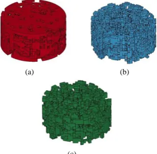
As a general approach, using Ansys freedom of tetrahedral mesh for cementitious composites division, SHPB bullet speed of 9m / s, taking the specimen diameter 74mm, 37mm radius of cementitious matrix composite specimen failure process was showed in Fig. 6 to 10.
(c)
Fig. 6. Numerical simulation of the structure of each phase specimens free meshing (a) Mortar matrix interior structure (b) Aggregate (c) ITZ.
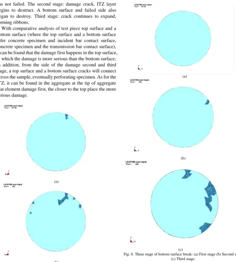
The first stage: the specimen initial damage in transmission bar and mortar contact face, the ITZ and the bottom surface has not failed. The second stage: damage crack, ITZ layer begins to destruct. A bottom surface and failed side also began to destroy. Third stage: crack continues to expand, forming ribbons.
With comparative analysis of test piece top surface and a bottom surface (where the top surface and a bottom surface refer concrete specimen and incident bar contact surface, concrete specimen and the transmission bar contact surface), it can be found that the damage first happens in the top surface, in which the damage is more serious than the bottom surface; In addition, from the side of the damage second and third stage, a top surface and a bottom surface cracks will connect across the sample, eventually perforating specimen. As for the ITZ, it can be found in the aggregate at the tip of aggregate that element damage first, the closer to the top place the more serious damage.
(a)
(b)
(c)
Fig. 7. Three stage of top surface break: (a) First stage (b) Second stage (c) Third stage.
(a)
(b)
(c)
In this experiment, the main link between the ITZ and mortar matrix damage is that where ITZ damage, the mortar matrix nearby would be destroyed, the final outcome reflected where the basic ITZ failure at the destruction of mortar matrix, aggregates only minor damage occurred in these places.
Free meshing cementitious composites produced by the process of crack damage is more similar to the actual situation, but it cost much of time to calculate. The above process required destruction of nearly 48 hours of computing time. The following rules would analyse the method of cementitious composites.
(a)
(b)
(c)
Fig. 9. Three stage of side break: (a) First stage (b) Second stage (c) Third stage.
(a) (b)
(c)
Fig. 10. Three stage of ITZ break: (a) First stage (b) Second stage (c) Third stage.
D. ProcessofRegularMesh Cement Based Composites under Dynamic Compression
Fig. 11. Cell size of 1.85 mm cementitious composite material specimen.
The cementitious composite specimens are 37mm high 74mm diameter as showed in Fig. 11.
(a) (b)
(c)
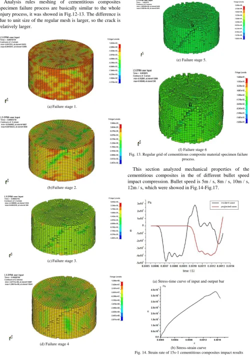
Analysis rules meshing of cementitious composites specimen failure process are basically similar to the whole injury process, it was showed in Fig.12-13. The difference is due to unit size of the regular mesh is larger, so the crack is relatively larger.
(a)Failure stage 1.
(b)Failure stage 2.
(c)Failure stage 3.
(d) Failure stage 4
(e) Failure stage 5.
(f) Failure stage 6
Fig. 13. Regular grid of cementitious composite material specimen failure process.
This section analyzed mechanical properties of the cementitious composites in the of different bullet speed impact compression. Bullet speed is 5m / s, 8m / s, 10m / s, 12m / s, which were showed in Fig.14-Fig.17.
(a) Stress-time curve of input and output bar
(b) Stress-strain curve
(a)Stress-time curve of input and output bar
(b) Stress-strain curve
Fig. 15. Strain rate of 34s-1 cementitious composites impact results.
(a)Stress-time curve of input and output bar
(b) Stress-strain curve
Fig. 16. Strain rate of 52s-1 cementitious composites impact results
(a)Stress-time curve of input and output bar
(b) Stress-strain curve
Fig. 17. Strain rate of 65s-1 cementitious composites impact results
IV. CONCLUSION
(1) With the meso-scale numerical technique, macroscopic mechanical behavior of cementitious composites dynamic was simulated in SHPB under compression, considering the material of cementitious composite material meso-scale heterogeneities.
(2)With regular mesh free mesh more computational advantages, the computing time is greatly shortened. The model of the interface damage in composite type is using this condition, and avoid the deformity unit division free mesh brings.
(3) In the meso-scale numerical simulation, cementitious composites under impact loading to failure from the ITZ or mortar matrix the weak point, and then destroy the extended crack formation, until the overall macro failure.
REFERENCES
[1] T. Chun and W. C. Zhu, Numerical Test of Damage and Fracture of Concrete, Beijing Science Press, 2003, pp. 34-44.
[2] Z. G. Liu and J. Chen, “Composite interface damage model in concrete fracture process and associated numerical simulation,” Journal of Central South University of Technology (Science and Technology), 2012, vol. 1, p. 43.
[3] G. W. Ma, A. Dong, and J. Li, “Modeling of structures subjected to impact: concrete behavior under high strain rate,” Cement and Concrete Composites, 2003, vol. 25, pp. 131-143.
[4] X. Q. Zhou and H. Hao, “Mesoscale modeling of concrete tensile failure mechanism at high strain rates,” Computers and Structures, 2008, vol. 86, pp. 21-22, 2013.
[6] X. W. Tang and C. H. Zhang, “Layering disposition and FE coordinate generation for random aggregate arrangements,” J T singh ua Un iv ( Sci & Tech ), 2008, vol. 48, pp. 48-52.
[7] S. M. Kim and R. K. A. A. Rub, “Meso - Scale computational modeling of the Plastic - damage reponse of cementitious composites,” Cement and Concrete Research, vol. 41, 2011, pp. 338-358.
[8] P. Grassl and M. Jirásek, “Meso-scale approach to modelling the fracture process zone of concrete subjected,” International Journal of Solids and Structures, vol. 47, 2010, pp. 957–968.
[9] V. P. Nguyen, M. Stroeven, and L. J. Sluys, “Multiscale failure modeling of concrete: Micromechanical modeling, discontinuous homogenization and parallel computations,” Comput. Methods Appl. Mech. Engry, pp. 201-204, 2012.
Fan Wang is a professor in the School of Mechanics and Construction Engineering, Jinan University, China. She got doctor's degree at the Lanzhou University in china. Her research interests include composite structure mechanics, nonlinear analysis of plate and shell. She is a vice president, Guangdong Society of Mechanics, China.
Chuanguo Zhong is engineering in the Guangzhou Building Materials Institute Limited Company, China. He got master’s degree at the Jinan University in China. His research interests include composite structure mechanics.
![Table I [2].](https://thumb-us.123doks.com/thumbv2/123dok_us/1356168.1644456/3.595.48.305.714.764/table-i.webp)