Effect of Optimum Arrangement of Conical
Turbulators with Twisted Tape on Heat Transfer
Enhancement in a Heated Tube
Khudheyer S. Mushatet, Baydaa A. Hussein
Mech. Eng. Dept. Mech. Eng. Dept. University of Thi-qar University of Thi-qarIraq Iraq e-mail: [email protected].
Abstract-- In this paper, an experimental and numerical
investigation has been conducted to predict the intensification of forced convection in a heated tube coupled with combined conical turbulators and twisted tape .Different arrangements of conical nozzle turbulators has been tested with different twist ratio as 3.0,5.0 and 7.0 respectively. The characteristics of complex turbulent flow and heat transfer augmentation is studied for Reynolds number variety of 15000 to 65000.The experimental results are obtained by constructing a test rig with sensors while the theoretical by using a numerical simulation based on a Fluent code .The obtained results show that the compound diverge conical turbulators with twisted tape has a superiority over those of the converge and converge-diverge arrangements. It is found that optimum enhancement in heat transfer is up to 237% for the diverge arrangement.
Index Term— Heat transfer, conical turbulators, twisted
tape.
1. INTRODUCTION
Heat transfer intensification systems are arranged into two directions: passive and active techniques. In the active procedures , heat transfer is improved by providing additional energy to the fluid .Some cases of active techniques are include the utilization of mechanical components, turning the surface, mixing fluid with mechanical extras and forming electrostatic regions in the flow area. The passive improvement can be gotten with no external energy[1].Different styles of turbulators tools have been connected to improve the heat transfer in a heat exchanger, for example, truncated hollow-cone, wire coil, conical nozzle, V-nozzle, and conical ring, etc [ 2]. Promvonge and Eiamsa [1], demonstrated that the utilizing of the conical turbulators and the snail can assist to intensification significantly the heat transfer contrasted with the empty tube by 288% and 207% respectively, and the usage of conical turbulators in combined with snail prompts to greatest heat transfer that is up by 326% for extent of Reynolds number was (8000-18000) at pitch ratios (2, 4 and7.0). Eiamsa et al [2] presented an experimental examinations of heat transfer and pressure loss attributes of turbulent flow through heated tube fixed with numerous orderly separated twisted tape. Results demonstrated that the smallest value of separating twisted tape provides the heat
however it can be reduced the pressure loss around 90%.Eiamsa et al [3] exhibited thermo hydraulic examination of turbulent flow during a heated tube furnished with twisted- tapes comprising of focus wings and alternate-axes . Totally twisted tapes utilized were twisted at steady twist length. The wings were created along the core line of the tape with three various angles of attack (43o,
53o,and 74o). Results demonstrated that the heat transfer
increased with intensifying angle of attack. Rahimi et al. [4]
augmented heat transfer supplementary the normal conical turbulators on the foundation of thermal performance of around 0.93 at the identical pumping. The thermal performance factor of 0.93 was discovered at the lowest pitch ratio and greatest number of holes. Bhuiya et al. [9] show the influences of double twisted -tape on heat transfer and performance factor characteristics in a heat exchanger for a turbulent flow with investigational technique. They discovered that the intensifications were around 62 – 241% and 92 – 287% for heat transfer and friction flow respectively in contrast to the smooth tube. Halit Bas and Ozceyhan [10] investigate the impact of the twisted tape added in a tube on heat transfer and friction factor properties. The impacts of twist ratios and clearance ratios were investigated in the range of Reynolds number from 5232 to 24,988.. For totally examined cases, heat transfer growth tends to reduce with the increase of Reynolds number and to be approximately unchanging for Reynolds number above 15,000 and twist ratio smaller than 3.0. Naga Sarada et al. [11] to display the influences of a horizontal tube fixed with differing width twisted tape on the heat transfer and performance factor characteristics . The Reynolds number was varied from 6000 to 13500. It was obtained that the increase of heat transfer with twisted -tape embeds as contrasted to plain tube varied from 36 to 49% for greatest width (26mm) and 34 to 39% for decreased width (22 mm) inserts. Experimental investigations were displayed by Aiwu et al . [12] to show the influences of a tube conical -strip on Nusselt number and performance factor .The results stated that the Nusselt number is improved by around 5 times that of the plain tube. An experimental study was reported by Eknath [13] to investigate the impact of the inclined Vortex- rings added in a tube on heat transfer and pressure loss properties. The sloping vortex rings were mounted repeatedly in the test tube with three various angles and three different width ratios at constant ring pitch- ratios .It is realized that the Nusselt number is greatest for vortex ring angle 350 with a
considerable rise in the pressure loss. Experimental examinations were expressed by Changzhong Man et al [14] to display the influences of a rotation of counter-clock wise and clockwise twisted tape and normal twisted tape inserted in the internal tube on Nusselt number and friction factor. The maximum value of performance valuation criteria of 1.42 was found with the utilization of full length and counter-clockwise twisted tape embed at Reynolds number
of 3800. The Nusselt number intensification was 2.42 times of that of the heated tube. Murugesan et al. [15] studied experimentally the turbulent heat transfer , pressure loss ,and thermal, enhancement factor, in a tube fitted, with typical twisted- tape, and U-cut twisted ,tapes for three various twist ratios. The average thermal enhancement for every one of the cases were above than unity demonstrated that the impact of heat transfer augmentation lead to the augmenting device is more predominate than the influence of increasing friction factor . Yadav and Padalkar [16] numerically examined the thermal enhancement and flow resistance characteristics in a circular tube with a partially decaying and partly swirl flow. The heat transfer and the pressure loss were evaluated at 10–57% and 32–144% greater than those in the plain tube state. It was obtained that thermal performance was augmented by utilizing a grouping of inserts with various geometries. Avinash Savekar et .al[17]studied numerically the effect of the twisted tape inserts in a heated tube on heat transfer mixing. It was found that, in the case of the tube embedded with twisted tape, alongside longitudinal movement there was movement of fluid particles in transversal direction because of the helically rotational fluid flow. Test examinations appeared by Kurhade Anant et.al [18] to show the influences of a twisted- tape embeds with circular perforations in a heated tube heat exchanger on Nusselt number and pressure loss. The Nussult number enhancement was observed to be 22.99%, 24.64% and 28.32% respectively. The intensification efficiency in a tube by utilizing plain twisted tape and semi-circular cut twisted tape was examined by Pawan et .al [19]. Greater Nusselt number was observed for Semi-Circular cut twisted- tape at twist ratio 3.5 and radius of cut ( R=10mm). It was noted that flow friction reduces for twist ratio equal to 3.5 and radius of cut 10 mm contrast with semi circular cut with twist ratio 3.5 and radius 5mm. Contrasting with plane tube, it was noticed that friction factor is higher for rising in cut radius.
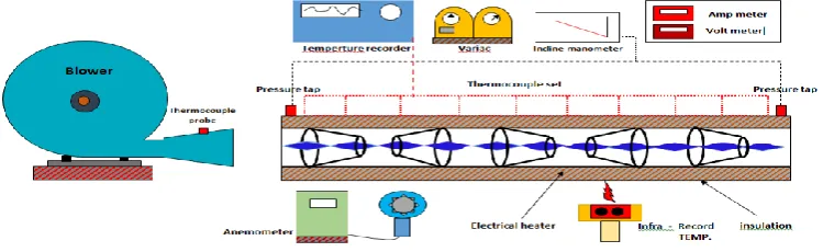
Fig. 1. Schematic diagram of the experimental rig
2. EXPERIMENTAL SET UP
The investigation was managed in an open loop experimental rig as presented in Fig. 1.The loop consisted of 1.1 KW blower, anemometer is utilized to measure the velocity of air inter through the test tube .The aluminum test tube has a length of L = 1200 mm, with 60.0 mm inner diameter (Di), 65.0 mm outer diameter (Do) and 2.5 mm thickness .The test section was heated by an electrical-wire continuously around the tube giving steady heat flux boundary condition . The electrical output power was regulated by a variac -transformer to get a constant heat flux along the whole longitude of the test section. The outside surface of the test tube was completely insulated to limit convective heat loss to the atmosphere, and the significant protections were taken to prevent leakages from the system. The recorder temperature was utilized to get temperature estimations. Ten thermocouples were appointed on the local wall of the tube to evaluate the temperature of the wall. Two thermocouple were located at the inlet and outlet of the
tube to quantify the temperature of the bulk air. Fig.1shows the heated tube with converge-diverge conical turbulators inserted with twisted tape. Fig .2. demonstrates that conical turbulators were made of aluminum with 60.0 mm in length and its small end diameter was 30 mm with a 1.5mm thickness and 120 mm as a pitch length. The twisted tapes made of aluminum with twist ratios of Y=y/w=3.0,5.0 and 7.0 respectively.
2.1.Twisted tape
The geometrical formation of twisted tape is offered in Fig .3 .The twisted tape was made from aluminum with length 1200mm ,thickness 1mm with width 15mm . It was manufactured by turning a straight tape about its longitudinal alignment. It is twisted with three changed twist ratios (Y/W) of 3.0 , 5.0 ,and 7.0 respectively for generating various swirl intensities.
3.DATA REDUCTION
In the present work, air is utilized as the working fluid that flowed across an insulated tube under a uniform heat flux. The steady state of the heat transfer rate is supposed to be equal to the heat loss from the test tube, which can be expressed as, Q air = Q conv………(1)
Where ;
Q air =m C p (To – Ti) = I.V………(2)
The convection heat transfer from the test section can be written as:
Q conv = h A(Tw –Tb )………. (3)
T b = (To +Ti ) / 2 ………. (4)
Tw = ∑ Tn / 10………… (5)
the average Nusselt number, Nu is valued as follows:
Nu = h D/ k …………. (6) The Reynolds number is given by:
Re = U.Dh / ν………. (7)
The friction factor (f) can be written as:
f = 2 ΔP (D/L)/ρ U2………(8)
Where U is the mean air velocity.
The thermal performance factor
is represented as: Ƞ = (Nut /Nup) / ( f / fo) 1/3…………(9)4. Mathematical Model and Numerical Method
4.1. Governing Equations
The considered flow is assumed as three dimensional, turbulent, steady with constant thermo physical properties. Neglecting heat conduction through twisting tape is also considered.
The continuity, momentum and energy equations are:
……… (10) ( …………(11
i jj i j i
u
u
x
U
x
x
P
j j i
x
U
U
j j ix
T
U
i jj i j
t
u
x
T
x
Pr
--- (12)
4.2 Boundary condition
The following boundary conditions are applied.
At inlet :
uniform inlet velocity is imposed
Tin=298 k
0At the walls :
At the pipe wall and twisted tape no slip condition is imposed (u=v=w=0).
constant heat flux
At outlet :
Gage pressure =0 .
4. 3.Numerical Method
For the present work, ANSYS Fluent 17 was selected as the CFD device. The finite volume technique with tetrahedral kind of mesh element was chosen as viewed in Fig. 16. The RNG k –ε turbulent model was utilized for treating the turbulence in the flow. The SIMPLE algorithm (Semi Implicit Method for Pressure-Linked Equations) was chosen .
Fig. 16. Tetrahedral mesh generated for tube occupied with converge-diverge conical with twisted -tape (CDTT) of P.R = 2.0.
4.4. Grid Generation
In order to assert precision of the numerical results, grid independence examinations were done. Three grids with various cells were used for every domain as presented. in Table1. The grid resolution investigation reveal that PT, CTT, CDTT and DTT become independent of the grid at cells 897.264, 3509560, 3527284 and 3520348 respectively.
5.RESULTS AND DISCUSSION
In this section ,the obtained result of Nusselt number ,friction factor and thermal performance factor are documented for different values of twist ratio, pitch length and Reynolds number.
5.1. Validation
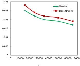
The collected experimental results are validated with existing related empirical correlations (eq .10 and eq.11) and with the published results of Promvonge [20] , eq.12 .The validation includes the Nusselt numbers and friction factor as demonstrated in Fig 4. , Fig .5 and Fig.6. The average deviation between the results is about 7.5% , 9% and 7.9% respectively.
Nu=0.023 Re 0.8 Pr 0.4 for Re ≥ 1 ×10⁴ ……….(10) f=o. 316 Re-1/4 for Re ≤ 2 x 10⁴………(11)
Re
Fig. 4. Validation of the present results of average Nusselt number with Dittus and Boltters correlation .
Re
Fig. 5. Validation the present results of average friction factor with Blasius correlation. 10
30 50 70 90 110 130 150 170 190
12000 17000 22000
present work
Dittus and Boltters
0 0.005 0.01 0.015 0.02 0.025 0.03
0 10000 20000 30000 40000 50000 60000 70000
Blassius
present work
N
u
f
Re
Fig. 6. Comparison of the present results with results of promvonge[ 20] for CD conical turbulators
5.2. Influence of twist ratio on Nusselt number and friction factor for converge conical turbulators.
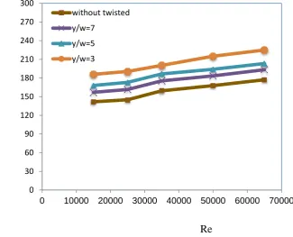
Fig.7.demonstrates the variety of average Nusselt number versus Reynolds number for different twist ratios .In general, it is observed that the average Nusselt number intensifies as Reynolds number rises. As twist ratio reduces the Nusselt number increase for the studied range of Reynolds number. The utilization of converge conical inserts leads to substantially greater heat transfer than the heated tube due to the influences of inverse flow and boundary layer disturbance which can assist to intensification the convection heat transfer and force process. The reverse flow rises the efficient axial velocity leads to advance the convection streams. As a consequence, more severe mean velocity and temperature slopes will be occurred, which generate greater fluxes of heat and motion due to higher efficient driving potential for all. Utilizing of twisted tape simultaneously with converge conical
turbulators produces twisting flow along the tube length , consequently, the disorganized mixing between the central and the wall areas will be improved, therefore augmenting the convective method.Considering the smaller of twist ratio,thegreater heat transfer is because increase strength of disturbance and flow length obtained.
The variety of friction factor with Reynolds number is appeared in Fig.8. It demonstrates that the mean friction factor reduces with rise in Reynolds number. The friction factor with combined influences of converge conical turbulators and twisted- tape is larger than that in the tube fitted with conical turbulators alone and the plain tube, and the smaller twist ratio leads to greater friction factor due to rise in swirl flow, leading to greater tangent contact between secondary stream and the wall surface of the tube. As can be noticed, there is a significant reduce in the friction factor at about 11% and 19% for utilizing Y/W= 5.0and 7.0,
individually, instead of Y/W= 3.0.
40 90 140 190 240 290
12000 14000 16000 18000 20000 22000 24000
present work
promvonge
N
u
Re
Fig. 7. Effect of twist ratio on Nusselt number variation for converge conical turbulators with twisted tape at P.R=2.
Re
Fig. 8. Effect of twist ratio on friction factor variation for converge conical turbulator with twisted tape at (P.R=2)5.3. Effect of twist ratio on thermal performance factor of converge conical turbulators .
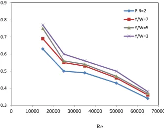
Effects of the twist ratio (Y/W) on the thermal performance are presented in Fig.9 .It is obtained that the thermal performance factor reduces with rising Reynolds number and it is also seen that the conical turbulators with the
smallest twist ratio (Y/W) provide the greater thermal performance factor. The greatest thermal performance factors at Y/W=3.0, 5.0, and 7.0, is found to be 0.77, 0. 75, and 0.69, respectively. The performance factors of the tube fitted with the conical turbulators alone are smaller than those of the tube with twisted -tape by around 10.5% to 18.1.5%.
0 30 60 90 120 150 180 210 240 270 300
0 10000 20000 30000 40000 50000 60000 70000
without twisted
y/w=7
y/w=5
y/w=3
0 0.2 0.4 0.6 0.8 1 1.2 1.4 1.6 1.8 2 2.2 2.4 2.6 2.8 3
0 10000 20000 30000 40000 50000 60000 70000
P.R=2
Y/W=7
Y/W=5
Y/W=3
f
Re
Fig. 9. Effect of twist ratio on thermal performance factor variation for converge conical turbulators with twisted tape at P.R=2
5.4. Effect the twist ratio on Nusselt number and flow friction variation for converge-diverge conical turbulators.
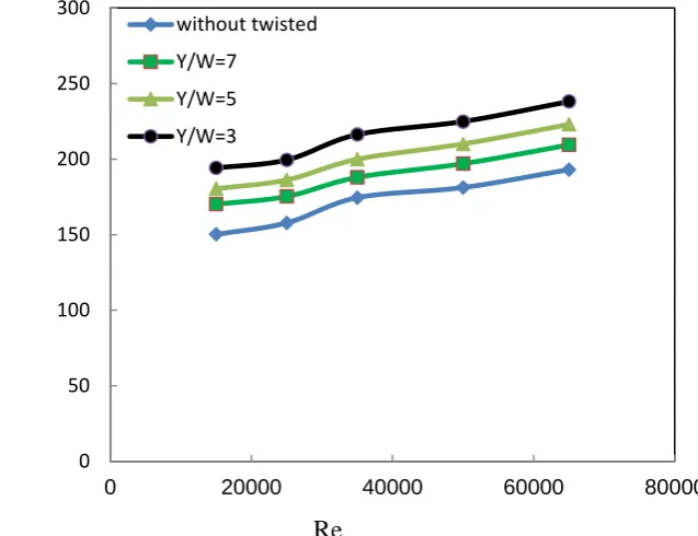
Fig. 10 demonstrates the variety of Reynolds number with the Nusselt number for different twist ratios. It is observed that Nusselt number rises with intensifying Reynolds number. The two devices give a significant intensify in heat transfer rate as contrasted with the plain tube. A close investigation exposes that the heat transfer from utilizing both converge-diverge conical with twisted-tape is larger than that from utilizing the converge – diverge conical alone. Generally, the conical turbulator is utilized to generate a recycling stream nearby the surface of the wall regime leading to modernization of thermal boundary layer .However the twisted-tape swirl generator to produce a swirl flow about the center area. A arrangement of the converge-diverge conical and the twisted-tape is utilized as a methods for intensifying heat transfer by together of reverse flow and swirl flow in a test tube. Heat transfer is augmented surprisingly if the converge-diverge conical is utilized in combination with the twisted -tape and the twisted -tape ratio is little (Y/W=3.0) to create a greater swirl flow. These occurrences result in a superior mixing of the stream between the wall and the center areas. The average Nusselt numbers for utilizing the conical turbulators together with
the twisted tape for Y=3.0,5.0 and 7.0, individually, are observed to be 22%,16% and 11%over that for utilizing the conical turbulators alone or to be around 366%,339%and 283% contrasted with the plain tube.
The influence of utilizing the converge-diverge conical turbulator in common with the twisted tape on the flow friction is demonstrated in Fig. 11. The average rise in friction factor of utilizing the two devises conical-turbulators with the twisted-tape is around 101 times over the plain tube. The pressure loss principally occurs from the greater friction of intensifying surface region because of the existence of the conical nozzle and from the dispersion of the dynamical pressure of the air because of great viscous losses nearby the wall, and to the additional forces applied by revolution or swirling stream. The expansion in friction factor of together the converge –diverge conical turbulators with the twisted-tape is up to 15% over that of the converge-diverge conical alone. The differentiation of friction factors from utilizing various twist ratios is little. The tendencies of the friction factor for every case are comparable and progressively reduce with intensifying Reynolds number. The greatest friction factor is obtained for utilizing the conical turbulator and the twisted tape with Y/W=3.0.
0.3 0.4 0.5 0.6 0.7 0.8 0.9
0 10000 20000 30000 40000 50000 60000 70000
P.R=2
Y/W=7
Y/W=5
Y/W=3
Re
Fig. 10. Effect of twist ratio on Nusselt number variation for converge-diverge conical turbulators with twisted tape at P.R=2.0
Re
Fig. 11. Effect of twist ratio on friction factor variation for converge-diverge conical turbulators with twisted tape at P.R=2.0
5.5. Effect of twist ratio ratio on thermal performance factor for converge diverge conical turbulators.
Fig .12 displays the variation of thermal performance factor with Reynolds number for the tube fitted with convege -diverge conical turbulators by inserts the various twist ratio of the- twisted tape . According to the results appeared above, the converge -diverge conical turbulator with twisted -tape offers heat transfer augmentation in accompany with
the rise of friction factor. The increase of friction factor causes increase of pumping energy. Thus , the real effectiveness of the turbulator relies on the weight of the enhance in heat transfer and the increase in friction, which can be resolved from performance evaluation . It is found that the thermal performance factor reduces with rising Reynolds number and it is also noticed that the twist ratio (Y/W=3.0) provide the highest thermal performance factor for converge-diverge conical turbulators.
0 50 100 150 200 250 300
0 20000 40000 60000 80000
without twisted
Y/W=7
Y/W=5
Y/W=3
0 0.5 1 1.5 2 2.5 3
0 10000 20000 30000 40000 50000 60000 70000
Y/W=5
Y/W=7
without tape
Y/W=3
N
u
f
Re
Fig. 12. Effect of twist ratio on thermal performance factor variation for converge-diverge conical turbulators with twisted tape at P.R=2.0
5.6. Effect the twist ratios on Nusselt number and flow friction for diverge conical turbulators.
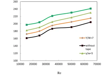
The influence of utilizing diverge conical-turbulator with twisted tape on the average Nusselt number is clarified in Fig.13. The average Nusselt number is greater than that of the conical turbulators alone at the similar Reynolds number. This can be ascribed to the diverge conical turbulators impact on the destruction of the thermal boundary layer nearby the surface of the test section of the tube which is caused by the obstruction of the air stream over the conical turbulators. Additionally , It is realized that the heat transfer rate intensifies with the reducing twist ratio (Y/W) as (Y/W=3.0,5.0 and 7.0) were 371%, 343% and 324% greater than those of the plain tube. The average
Nusselt numbers for utilizing the conical turbulators together with the twisted tape for Y=3.0,5.0 and 7.0, respectively are observed to be 18%,11% and 6%over that for utilizing the conical turbulators alone .
Fig.14. displays the variety of the friction factor with Reynolds number for three various twist ratios .As can be viewed, the friction factor is larger than that for conical alone for the similar Reynolds number and it decreases with rise in Reynolds number for all twist ratios. The friction factor for diverge conical turbulators is greater than the plain tube and the smaller twist ratio leads to greater friction factor due to the dispersion of dynamic pressure of the fluid due to greater surface region and the action produced by the reverse flow.
0.3 0.4 0.5 0.6 0.7 0.8 0.9
0 10000 20000 30000 40000 50000 60000 70000
Series1
Series2
Series3
Series4
Ƞ
Re
Fig. 13. Effect of twist ratio on Nusselt number variation for diverge conical turbulator with twisted tape at P.R=2.
Re
Fig. 14. Effect of twist ratio on friction factor variation for diverge conical turbulators with twisted- tape at P.R=(2.0).
5.7. Effect of twist Ratio on thermal performance factor of diverge conical turbulators .
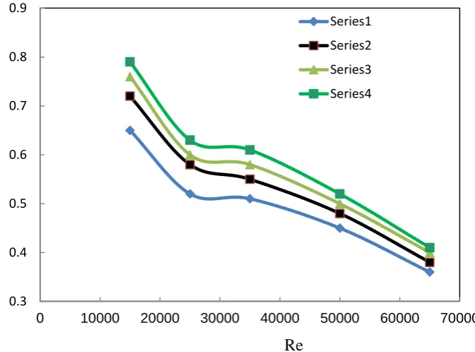
It is significant to assess the performance of both intensification system that has been utilized in the present investigation to locate the most applied technique, This assessment is done by calculating together influences of the intensification device; on the Nusselt number and on the
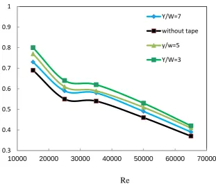
friction factor simultaneously by exhibiting them in to the structure of the thermal performance factor . Fig.15 represents that for the diverge conical turbulator with twisted tape at twist ratio Y/W=3.0 provides the greatest average value of thermal performance factor of 0.80, while the twist ratio Y/W=5.0 and with the twist ratio Y/W=7.0
provided 0.77 and 0.73 respectively.
100 120 140 160 180 200 220 240 260
10000 20000 30000 40000 50000 60000 70000
Y/W=7
without tape y/w=5
0.5 1 1.5 2 2.5 3
10000 20000 30000 40000 50000 60000 70000
Y/W=7
without tape y/w=5
y/w=3
N
u
f
Re
Fig. 15. Effect of twist ratio on thermal performance factor variation for diverge conical turbulator with twisted tape at P.R=2.
5.8. Comparison between the experimental and numerical results
In this section , the experimental Nusselt numbers for the CTT, CDTT and DTT is contrasted with those acquired
from numerical work. As shown in Fig.17 to 19. It can be seen the deviation between the results is about 13%,11% and10%for CTT,CDTT and DTT, respectively .
0.3 0.4 0.5 0.6 0.7 0.8 0.9 1
10000 20000 30000 40000 50000 60000 70000
Y/W=7
without tape
y/w=5
Y/W=3
50 70 90 110 130 150 170 190 210 230
0 10000 20000 30000 40000 50000 60000 70000
experimental
therotical
ᵑ
N
u
5.9. Flow Field
The velocity vectors at a pivotal location of 0.217m are displayed in Fig. 20. The tangential velocity in the plain tube (frame A) is approximately zero and therefore createing the swirl near the wall is to vanish and weaken the swirl in the whole area. When the plain tube is induced with combined conical turbulators with twisted tape embed the
tangential velocity rises and swirl flow is produced around the converge conical and twisted -tapes (frame B).When the conical turbulators are replaced by changing their arrangement (frame C and D), the tangential velocity becomes greater and the swirl becomes stronger. Thus the pattern of the swirl varies from one tube to another as a
50 70 90 110 130 150 170 190 210 230 250
0 10000 20000 30000 40000 50000 60000 70000
experimental
therotical
50 70 90 110 130 150 170 190 210 230 250
0 10000 20000 30000 40000 50000 60000 70000
therotical
experimental
N
u
Re
Fig. 19. Comparison between experimental and theoretical works for diverge conical turbulators with twisted tape
N
u
Re
result of the various arrangement of the conical inserts in the tubes.
5. 10.Temperature Contour
The contours of temperature at an axial location of the conical turbulators with twisted tape embeds for the turbulent flow are presented in Fig. 21. When the plain tube is induced with a converge conical turbulators with twisted tape (frame B), the thermal boundary becomes thinner. Additionally, the temperature slope becomes larger. Therefore, the temperature distribution in converge conical with twisted tape (frame B) is better than that of plain tube
(frame A). With the replacement of the test tube with converge –diverge conical and twisted tape (frames C) the boundary layer thickness is further decreased and more swirls are produced. These result in superior temperature distribution. The tube induced with diverge conical with twisted -tapes (frames D ) have better mixing than those conical arrangement . Consequently, the temperature distribution in DTT are better than those in CTT, CDTT and PT.
Fig. 21. Temperature contour for PT (A), CTT (B), CDTT (C), and DTT (D) for Re=15000 at axial location of 0.217m.
6.CONCLUSION
The heat transfer intensification in a heated tube by using combined conical turbulators and twisted tape has been experimentally and numerically investigated .In this section
1.The heat transfer in the heated tube could be augmented highly by fitting it with diverge conical turbulators with twisted tape inserts.
2. Conical nozzle turbulators with or without twisted tape
B
C
E
A
B
C
D
A
transfer rate. However, the pressure loss has been found to increase.
3. Twisted tape inserted inside a heated tube fitted with diverge conical turbulators are offered greater heat transfer rates by about 18% as compared with those of the test tube fitted with conical turbulators alone.
4. The optimum enhancement efficiency of 371 % is found for diverge conical turbulators with twisted tape at P.R=2.0 . 5. Over the range tested, the highest thermal performance factor of 80 % is found by use of diverge conical turbulators with twisted tape for Y/W=3.0.
6. The overall thermal performance factor for converge-diverge and converge conical turbulators with twisted- tape is obtained to be smaller than diverge conical with twisted -tape insert.
NOMENCLATURE
A surface area of the test tube (m2)
C p specific heat capacity (J/Kg K)
CTT converge turbulators with twisted tape
CDTT converge –diverge conical turbulators with twisted tape
DTT diverge conical turbulators with twisted tape
Di inner diameter of the test tube (m)
Do outer diameter of the test tube (m)
f friction factor
f0 friction factor at the plain tube
h average heat transfer coefficient (W/m2k)
k thermal conductivity (W/m K)
l the length between conical ( m)
L length of the test tube( m)
m air mass flow rate( kg/s)
Nu Nusselt number
ΔP pressure drop (pa)
P.R pitch ratio of the conical turbulator
PT plain tube
Q heat transfer rate ( W)
Re Reynolds number
t thickness of the test tube (m)
Tw wall temperature (C0)
Tb bulk temperature ( C0 )
U mean velocity in the test tube (m/s)
Y/W twist ratio of the twisted tape
Greek symbols
ʋ kinematics viscosity ( m2/s)
Ƞ Thermal performance factor
ρ fluid density (kg/m3)
REFERENCES
[1] P. Promvonge and S. Eiamsa-ard, "Heat transfer enhancement in a tube withcombined conical-nozzle inserts and swirl generator", Energy Conversion and Management, Volume 47, pp.2867–2882, 2006.
[2] Eiamsa-ard, S. , Thianpong C, and Promvonge, P",Experimental investigation of heat transfer and flow friction in a circular tube fitted with regularly spaced twisted tape elements",International Communication in Heat and Mass Transfer
[3] Eiamsa, S., Wongcharee, K. ,Eiamsa-ard, P. , and P. , andThianpong, C. , "Thermohydaulic investigation of turbulent flow through a round tube equipped with twisted tapes consisting of center wings and alternate-axes",Experimental Thermal and FluidScience, online, 24 April 2010.
[4] M. Rahimi, S.R. Shabanian, A.A. Alsairafi, Experimental and CFD studies on heat transfer and friction factor characteristics of a tube equipped with modified twisted tape inserts, Chem. Eng. Process. 48 (2009) 762–770.
[5] S. Eiamsa-ard and P. Promvonge, "Experimental investigation of heat transfer and friction characteristics in a circular tube fitted with v-nozzle turbulators",International Communication in Heat and Mass Transfer, Volume 33, pp.591-600,2006. [6] P. Promvonge and S. Eiamsa-ard, "Heat transfer and turbulent
flow friction in acircular tube fitted with conical-nozzle turbulators", International Communications in Heat and Mass Transfer, Volume 34, pp.72–82, 2007.
[7] H. Karakaya and A. Durmus, "Heat transfer and exergy loss in conical spring turbulators", International Journal of Heat and Mass transfer, Volume 60, pp.756-762,2013.
[8] V. Kongkaitpaiboon, K. Nanan and S. Eiamsa-ard, "Experimental investigation of heat transfer and turbulent flow friction in a tube fitted with perforated conicalrings",International Communications in Heat and Mass Transfer, Volume 37,pp.560-567, 2010.
[9] M.M.K. Bhuiya, A.S.M. Sayem, M. Islam, M.S.U. Chowdhury, M. Shahabuddin, “Performance assessment in a heat exchanger tube fitted with double counter twisted tape inserts”, International Communications in Heat and Mass Transfer, Elsevier, vol. 50, pp. 25–33, 2014.
[10] Halit Bas and Veysel Ozceyhan, Heat Transfer Enhancement in a Tube with Twisted Tape Inserts placed Separately from the Tube Wall, Experimental Thermal and Fluid Science Vol.41, pp 51-58, 2012.
[11] Naga Sarada S., Sita Rama A.V., Kalyani Radha K., and Shyam Sunder L.; Enhancement of Heat Transfer using Varying Width Twisted Tape Inserts,International Journal of Engineering , Science and Technology, Vol.2, No.6, pp 107-118, 2010. [12] Aiwu et al., A numerical study on thermo-hydraulic
characteristics of turbulent flow in a circular tube fitted with conical strip inserts ,Applied Thermal Engineering, vol 31, (2011) ,pp.2819-2828.
[14] Changzhong Man, et.al Experimental study on effect of heat transfer enhancement for singlephase forced convective flow with twisted tape inserts, International Journal of Heat and Mass Transfer,2016.
[15] Murugesan et al. Heat Transfer and Friction Factor in a Tube Equipped with U-cut Twisted Tape Insert, Jordan Journal of Mechanical and Industrial Engineering Volume 5, Number 6, Dec. 2011 ISSN 1995-6665 Pages 559 - 565,
[16] Yadav and Padalkar CFD Analysis for Heat Transfer Enhancement inside a Circular Tube with Half-Length Upstream and Half-Length Downstream Twisted Tape Journal of Thermodynamics, Volume 2012,1-12.
[17] Avinash Savekar et .al "Analysis of Heat Transfer in Pipe with Twisted Tape Inserts, International Conference on Fluid Flow", Heat and Mass Transfer Ottawa, April 30 – May 1, 2015. [18] Kurhade Anant et.al heat transfer enhancement by using twisted
tape inserts with circular hole in forced convection ,International Journal of Innovations In Engineering ,volume 3,issue 3, Mar
-2016
[19] Pawan et .al, Experimental Analysis of Augmentation in Heat Transfer Coefficient Using Twisted Tape with Semi-Circular Cut Insert,International Journal of Science and Research, 2013, 1174-1179 promvonge, Heat transfer behavior in round tube

![Fig. 6. Comparison of the present results with results of promvonge[ 20] for CD conical turbulators](https://thumb-us.123doks.com/thumbv2/123dok_us/1352775.1643911/7.595.100.442.66.311/fig-comparison-present-results-results-promvonge-conical-turbulators.webp)