IJIRT 148929
INTERNATIONAL JOURNAL OF INNOVATIVE RESEARCH IN TECHNOLOGY66
Performance Analysis of Induction Motor Drive using
SVPWM
Miss. Tejashri S. Mahajan
1, Mr. V. S. Pawar
21
PG Student Scholar, Dept. of EEE, SSBT’S College of Engineering & Technology, Jalgaon, M.H, India
2Professor, Dept. of EEE, SSBT’S College of Engineering & Technology, Jalgaon, M.H, India
Abstract- In this project speed of induction motor is controlled which is fed from three phase bridge inverter. In this paper the speed of an induction motor can be varied by varying input Voltage or frequency or both. Variable voltage and variable frequency for Adjustable Speed Drives (ASD) is invariably obtained from a three-phase Voltage Source Inverter (VSI). Voltage and frequency of inverter can be easily controlled by using PWM techniques, which is a very important aspect in the application of ASDs. A number of PWM techniques are there to obtain variable voltage and variable frequency supply such as PWM, SPWM, SVPWM to name a few, among the various modulation strategies SVPWM is one of the most efficient techniques as it has better performance and output voltage is similar to sinusoidal. In SVPWM the modulation index in linear region will also be high when compared to other region.
Index terms- Pulse width modulation, Space vector PWM, Total Harmonic Distortion
I.INTRODUCTION
An adjustable speed drive (ASD) is a device used to provide continuous range process speed control. An ASD is capable of adjusting both speed and torque from induction or synchronous motor. An electric ASD is an electrical system used to control motor speed. ASDs may be referred to by a variety of names, such as variable speed drives, adjustable frequency drives or variable frequency inverters. The two terms adjustable frequency drives or variable frequency inverters will only be used to refer to certain AC systems, as is often the practice, although some DC drives are also based on the principle of adjustable frequency (Switching frequency of chopper switch). Adjustable speed drives are the most efficient (98% at full load) types of drives. They are used to control the speeds of both AC and DC
motors. They include variable frequency/voltage AC motor controllers for squirrel-cage motors, DC motor controllers for DC motors, eddy current clutches for AC motors (less efficient), wound-rotor motor controllers for wound-rotor AC motors (less efficient) and cycloconverters (less efficient).
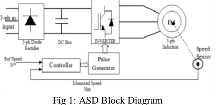
Fig 1: ASD Block Diagram
A squirrel cage induction motor with constant frequency, constant magnitude voltage supply is supplied, the motor provides constant torque and speed characteristic. To regulate the speed and torque for same induction motor, the motor has to run at variable voltage and frequency. The variable voltage and variable frequency can be obtained from (ASD) adjustable speed drives. AC to DC converter is the first step by which we get DC voltage from AC utility grid. This step is called rectification it occurs by diodes connected in bridge form. The second step is DC to AC by operating in inversion operation mode is called inverter device. The converter in ASD is operated in such a way that too obtained variable voltage and frequency at the output of the ASD by which motor speed, torque can be controlled with high performance.
II. PULSE WIDTH MODULATION (PWM)
IJIRT 148929
INTERNATIONAL JOURNAL OF INNOVATIVE RESEARCH IN TECHNOLOGY67
supply AC current to the load by converting the DC current and it appears as an AC signal at load or can control the speed of motors that run at high speed or low. The duty cycle of a PWM signal varies through analog components, a digital microcontroller or PWM integrated circuits.
Triangular wave is formed by op-amp driver. Triggering pulses are produced at the instant of the carrier signal magnitude is greater than the reference signal magnitude. To turn-on the IGBT switches, firing pulses are produced, the output voltage during the interval triangular voltage wave stipulated the square modulating wave.
A number of PWM techniques are there to obtain variable voltage and frequency supply such as, (i) Single-pulse modulation
(ii) Multiple-pulse modulation
(iii) Selected harmonic elimination PWM (iv) Minimum ripple current PWM (v) Sinusoidal-pulse PWM (SPWM) (vi) Space vector-pulse PWM (SVPWM)
Single Pulse Modulation:
The output voltage waveform of single pulse full-bridge inverter is modulated, it contains pulse of width located symmetrically about ʌ/2 and another pulse located symmetrically about 3ʌ/2. The range of pulse width 2d varies from 0 to ʌ; i.e.0<2d<ʌ. The output voltage is controlled by varying the pulse width 2d. This shape of the output voltage wave is called quasi-square wave.
Multiple-pulse modulation:
This method of pulse modulation is an extension of single-pulse modulation. In this method, several equidistant pulses per half cycle are used.
Selected harmonic elimination PWM:
The undesirable lower order harmonics of a square wave can be eliminated and the fundamental voltage can be controlled as well by what is known as selected harmonic elimination (SHE) PWM. A large no. of harmonics can be eliminated if the waveform can accommodate additional notch angles.
Minimum ripple current PWM:
One disadvantage of the SHE PWM method is that the elimination of lower order harmonics considerably boosts the next higher level of
harmonics. Since the harmonic loss in a machine is dictated by the RMS ripple current, it is the parameter that should be minimized instead of emphasizing the individual harmonics.
Sinusoidal-pulse PWM (SPWM):
Sinusoidal PWM is a modulation technique in which a sinusoidal signal is compared with the triangular signal, in which the frequency of triangular signal (ftri) is equals to the desired sinusoidal output and the frequency of triangular signal gives the switching frequency of the switches.
The magnitude of o/p voltage depends on modulation index which is defined as, “the ratio Vtri/VC is called Modulation Index (Ma)” and it controls the harmonic content of the output voltage waveform.
III. SPACE VECTOR-PULSE PWM (SVPWM)
It is an algorithm for the control of pulse width modulation (PWM). SVPWM is used for producing alternating current (AC) waveforms. It is frequently used to drive 3-phase AC powered motors at variable speed from DC power. Various variations of SVPWM that result in different quality and computational requirements. The development is in the reduction of total harmonic distortion (THD) created by the rapid switching inherent to these algorithms.
Space vector modulation is a PWM regulator algorithm for multi-phase AC generation. The reference signal is sampled frequently, after each sample, non-zero active switching vectors adjacent to the reference vector and one or more of the zero switching vectors are preferred for the suitable fraction of the sampling period in order to integrate the reference signal as the average of the used vectors.
Principle of Space Vector PWM
IJIRT 148929
INTERNATIONAL JOURNAL OF INNOVATIVE RESEARCH IN TECHNOLOGY68
is generated by two adjacent non -zero vectors and two zero vectors.
Basic switching vectors and Sectors
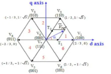
Six active vectors are (V1, V2, V3, V4, V5, V6).DC link voltage is supplied to the load. Each sector (1 to 6): 60 degrees. Two zero vectors are (V0, V7). They are located at the origin. No voltage is supplied to the load.
Fig 2: Basic Switching vectors and sectors
IV SPACE VECTOR MODULATION
Space vector modulation (SVM) is based on vector selection in the q -d stationary reference frame. The commanded voltage vector is defined by equation -3.5. The commanded vector is plotted along with the vectors obtainable by the inverter. The desired vector V s*qds is shown at some point in time but will follow the circular path if a three-phase set of voltages are required on the load.
Fig 3:Voltage Space Vector and its components in (d, q)
Step -1 Determine Vd, Vq, Vref,
Step -2 Determine time duration T1, T2, T0
Step-3Determine the switching time of each transistor (S1to S6)
Coordinate transformation: abc to dq
𝑉𝑑=𝑉𝑎𝑛− 𝑉𝑏𝑛 .cos60−𝑉𝑐𝑛 .cos60 = 𝑉𝑎𝑛− 12𝑉𝑏𝑛−1/2𝑉𝑐𝑛
𝑉𝑞=0+ 𝑉𝑏 . cos30− 𝑉𝑐 . cos30 = 𝑉𝑎𝑛 + √32𝑉𝑏𝑛− √32𝑉𝑐𝑛
[𝑉𝑑𝑉𝑞] = [231−12−120√32−√32][𝑉𝑎𝑛𝑉𝑏𝑛𝑉𝑐𝑛] |𝑉 𝑟𝑒𝑓| = √𝑉𝑑2+𝑉𝑞2
𝛼= tan−1(𝑉𝑞𝑉𝑑) = 𝜔𝑠𝑡 = 2𝜋𝑓𝑠𝑡 Where, 𝑓𝑠 = fundamental frequency
Switching time duration at sector 1 is described below
∫𝑉 𝑟𝑒𝑓𝑇𝑧0= ∫𝑉 1𝑇10𝑑𝑡+ ∫𝑉 2𝑇1+𝑇2𝑇1𝑑𝑡+
∫𝑉 0𝑇𝑧𝑇1+𝑇2 𝑇 .𝑉 𝑟𝑒𝑓 = (𝑇1.𝑉 1+ 𝑇2.𝑉 2)
𝑇𝑧.|𝑉 𝑟𝑒𝑓|.[cos (𝛼)sin (𝛼)] = 𝑇1.23 .𝑉𝑑𝑐.[cos (𝜋3⁄)𝑠𝑖𝑛(𝜋3⁄)] where, 0≤𝛼≤60°
𝑇1= 𝑇𝑧 .𝑎.sin(𝜋3⁄)−𝛼𝑠𝑖𝑛(𝜋3⁄) 𝑇2= 𝑇𝑧 .𝑎.sin (𝛼)sin (𝜋3⁄) 𝑇0= 𝑇𝑧− (𝑇1+𝑇2),
where, 𝑇𝑧= 1𝑓𝑠 and a = |𝑉 𝑟𝑒𝑓|23𝑉𝑑𝑐
Switching time duration at any Sector is shown below
𝑇1= √3 𝑇 .|𝑉 𝑟𝑒𝑓|𝑉𝑑𝑐 (sin(𝜋3−𝛼+ 𝑛−13𝜋) = √3 .𝑇𝑧. |𝑉 𝑟𝑒𝑓| 𝑉𝑑𝑐 (𝑠𝑖𝑛𝑛3𝜋−𝛼)
= √3 .𝑇𝑧 .|𝑉 𝑟𝑒𝑓|𝑉𝑑𝑐 (𝑠𝑖𝑛 𝑛3𝜋𝑐𝑜𝑠𝛼−𝑐𝑜𝑠𝑛3𝜋𝑠𝑖𝑛𝛼) 𝑇2=√3 .𝑇𝑧 .|𝑉 𝑟𝑒𝑓|𝑉𝑑𝑐 (sin (𝛼−𝑛−13𝜋))
= √3 .𝑇𝑧 .|𝑉 𝑟𝑒𝑓|𝑉𝑑𝑐 (−cos𝛼 . sin 𝑛−13𝜋+ sin𝛼 . cos𝑛−13𝜋)
𝑇0= 𝑇𝑧− 𝑇1−𝑇2
Where, n=1 through 6(that is sector 1 to 6), 0≤𝛼≤60° A three phase power inverter is shown below
Fig 4: Three-phase Power inverter
IJIRT 148929
INTERNATIONAL JOURNAL OF INNOVATIVE RESEARCH IN TECHNOLOGY69
Table 1: Switching time table at each sector
The most popular three-phase voltage source inverter (VSI) consists of a six-switch topology. The topology can generate a three-phase set of ac line voltages such that each line voltage vab features a fundamental ac line voltage vab1 and unwanted harmonics. The fundamental ac line voltage is usually required as a sinusoidal waveform at variable amplitude and frequency, and the unwanted harmonics are located at high frequencies. These requirements are met by means of a modulating technique as shown earlier. Among the applications in low-voltage ranges of six-switch VSIs are the adjustable speed drives
(ASDs). The range is in low voltages due to:
(a) The high dv/dt present in the PWM ac line voltages , which will be unacceptable in the medium- to high-voltage ranges and
(b) The load power would be shared only among six switches. This may require paralleling and series-connected power valves, an option usually avoided as symmetrical sharing of the power is not natural in these arrangements. Two solutions are available to generate near-sinusoidal voltage waveforms while using six-switch topologies. The first is a topology based on a CSI in combination with a capacitive filter. The second solution is a topology based on a VSI including an inductive or inductive/capacitive filter at the load terminals. Although both alternatives generate near-sinusoidal voltage waveforms, both continue sharing the load power only among six power valves. Solutions based on multistage voltage source topologies have been proposed. They provide medium voltages at the ac terminals while keeping low dv/dt s and a large number of power valves that symmetrically share the total load power. The multistage VSIs can be classified in multi cell and multilevel topologies.
V OUTPUT VOLTAGES OF THREE-PHASE INVERTER
S1through S6are the six power transistors that shape the output voltage. When an upper switch is turned on (i.e., a, b or c is “1”), the corresponding lower switch is turned off (i.e., a', b' or c' is “0”). Eight possible combinations of on and off patterns for the three upper transistors (S1, S3, S5) are possible. Line to line voltage vector [Vab Vbc Vca]t.
Table 2: Phase voltages andnoutput line to line voltages in SVM
VI. SIMULATION AND RESULTS
SIMULATION OF SINUSOIDAL PWM BASED MODEL
Here the three-phase 415V, 50Hz ac supply is converted into dc and then this DC voltage is converted into 3-phase variable frequency ac. Here the controlling of an inverter is done by PWM method i.e. sinusoidal PWM.
Fig 5: Inverter o/p line voltages
IJIRT 148929
INTERNATIONAL JOURNAL OF INNOVATIVE RESEARCH IN TECHNOLOGY70
Fig 6: Motor Speed and Electromagnetic torque
SIMULATION OF SPACE VECTOR PWM BASED MODEL
SVPWM based pulse generator simulation diagram is as shown in Fig. 7 The switching times of switches T1, T3 and T5 are determined in the block MATLAB function block to which some parameters are given such as sector number, angle (Į), Vref and sampling time. The switching times T1, T3 and T5 are calculated in 6 sectors individually by changing the sector. The output of the block is T1, T3 and T5 which is again compared with the high-frequency carrier wave so as to reduce the harmonics in the output of the inverter. And T4, T6 and T2 are the inverted switching times of T1, T3 and T5 respectively.
T1 to T6 pulse signals are as shown in Figure7. These pulsed are given to the six IGBT switches of bridge inverter.
Fig 7: SVPWM output gate pulses
When SVPWM pulse generator is connected to 3-phase bridge inverter with the induction motor load form an open loop drive. The motor will run at a reference speed. The reference speed command is converted into frequency command and given to SVPWM block. The SVPWM block generates gate pulses with respect to speed command so as to run the motor at reference speed.
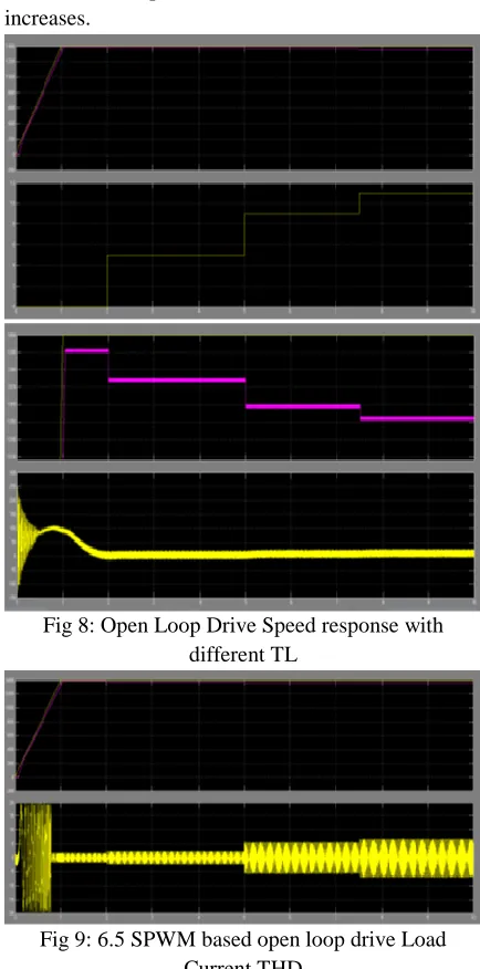
Speed response of Induction motor with different load torque is as shown in below Fig. For 1400rpm of constant input speed command and different load torque at the different instant has been applied therefore the speed of motor will falls as load increases.
Fig 8: Open Loop Drive Speed response with different TL
Fig 9: 6.5 SPWM based open loop drive Load Current THD
IJIRT 148929
INTERNATIONAL JOURNAL OF INNOVATIVE RESEARCH IN TECHNOLOGY71
Table 3: Open Loop Model Variation of motor speed with Load torque
Table 4: Open Loop Model Variation of motor speed with Load torque
To maintain the motor speed at a reference speed value, it needs a feedback loop of motor speed and a speed controller. The drive requires a speed sensor, and the output of the speed sensor will be in terms of rpm.
VII. CONCLUSION
The simulation of “Performance analysis of Induction Motor Drive Using Space Vector PWM” is carried out in MATLAB/Simulink. The simulation has been done for open loop as well as closed control. The appropriate output results are obtained. The variation of speed of Induction Motor has been observed by varying the load torque in open loop control and results are noted down in the table. Also observed that for the change in input speed commands the motor speed is settled down to its final value within 0.1sec in closed loop model.
REFERENCES
[1] Abdelfatah Kolli, Student Member, IEEE, Olivier Béthoux, Member, IEEE, Alexandre De Bernardinis, Member, IEEE, Eric Labouré, and Gérard Coquery “Space-Vector PWM Control Synthesis for an H-Bridge Drive in Electric
Vehicles” IEEE TRANSACTIONS ON
VEHICULAR TECHNOLOGY, VOL. 62, NO. 6, JULY 2013. pp. 2241-2252.
[2] Mr. Sandeep N Panchal, Mr. Vishal S Sheth, Mr. Akshay A Pandya “Simulation Analysis of SVPWM Inverter Fed Induction Motor Drives” International Journal of Emerging Trends in Electrical and Electronics (IJETEE) Vol. 2, Issue. 4, April-2013. pp. 18-22
[3] Haoran Shi, Wei Xu, Chenghua Fu and Yao Yang. “Research on Threephase Voltage Type
PWM Rectifier System Based on SVPWM Control” Research Journal of Applied Sciences, Engineering and Technology 5(12): 3364-3371, 2013. pp. 3364-3371.
[4] K. Mounika, B. Kiran Babu, “Sinusoidal and Space Vector Pulse Width Modulation for Inverter” International Journal of Engineering
Trends and Technology (IJETT) -
Volume4Issue4- April 2013. pp.1012-1017. [5] K. Vinoth Kumar, Prawin Angel Michael,
Joseph P. John and Dr. S. Suresh Kumar. “Simulation And Comparison Of Spwm And Svpwm Control For Three Phase Inverter” ARPN Journal of Engineering and Applied Sciences VOL. 5, NO. 7, JULY 2010. pp. 61-74. [6] Keliang Zhou and Danwei Wang, Member, IEEE
“Relationship Between Space-Vector
Modulation and Three-Phase Carrier-Based PWM: A Comprehensive Analysis” IEEE
TRANSACTIONS ON INDUSTRIAL
ELECTRONICS, VOL. 49, NO. 1, FEBRUARY 2002.pp. 186-196.
[7] Dorin O. Neacsu, “Space Vector Modulation – An Introduction” IECON’01: The Annual Conference of the IEEE Industrial Electronics Society-2001. pp. 1583-1592.
[8] C. Wang and Y. Li, “A survey on topologies of multilevel converters and study of two novel
topologies,” in 2009 IEEE 6th
InternationalPower Electronics and Motion Control Conference, 2009, pp. 860- 865.
[9] M. A. Boost and P. D. Ziogas, “State-of-the-art carrier PWM techniques:a critical evaluation,” IEEE Transactions on Industry Applications,vol. 24, no. 2, pp. 271-280, 1988.
[10]J. Holtz, “Pulsewidth modulation-a survey,” IEEE Transactions on Industrial Electronics, vol. 39, no. 5, pp. 410-420, 1992.
[11]A. M. Hava, R. J. Kerkman, and T. A. Lipo, “Carrier-based PWM VSI overmodulation strategies: analysis, comparison, and design,” IEEE Transactions on Power Electronics, vol. 13, no. 4, pp. 674-689, 1998.