Analysis and Review of EDFA
1
Dipika Pradhan, 2 Vivekanand Mishra
1, 2
Department of Electronics and Communication Engineering, S. V. National Institute of Technology Surat, India
Abstract - Optical fiber communication is the best transmitting data may be capable of Terabit per second data rate. No existing single communication system can make complete use of this speed. Many types of Optical amplifiers have been developed to amplify optical signal. EDFA is one of the examples of optical fiber amplifier to amplify optical signal. To design optical amplifier gain and NF are most significant points. Gain and NF are more significant points. Gain and NF have very strong impact on EDFA configurations. This paper focused on four important sections. First section is EDFA have enabled to use WDM, DWDM Technique, which uses denser channel spacing in order to achieve higher bit rates. The second section is based on the theoretical background of EDFA analysis and the parameters used for amplification related to spontaneous and stimulated emission. The third section is configuration of EDFA from the single pass to the quadruple pass. The fourth section is the different methods used for gain flattening of EDFAs depends on a large number of device parameters such as erbium ion concentration, amplifier length, pump power and core radious.
Keywords – EDFA, WDM, DWDM, Gain Flattening.
1. Introduction
Optical fiber communication is the most reliable telecommunication technologies to achieve customer needs for present and future applications. System capacity can be increased by 1) deploying new optical fiber,2) increasing transmission bit rate 3) multiplexing more channels on to the existing fiber.Optical transmission systems are based on the principle that light can carry more information in a glass medium over longer distances. Optical fiber is a waveguide doped with Neodymium Nd3+ used in a single mode fiber was demonstrated in 1960(James,1991).The DFA are achieved with elements such as praseodymium (Pr3+) through doping fluoride based fibers (kunihiko,1998),Europium (Eu3+) with 613nm windows(Lihue 2004) and Neodymium (Nd3+) with 730 nm windows (Jouin,2002).DFA has less attenuation is operating in the 1550nm window by doping silica fiber core with Erbium(Er3+).EDFA could provide gains as 40dB associated with less noise with pump power range 50 to 100MW (Mears,1987).A highly efficient gain
clamped can be achieved by simply adding c-band fiber brag grating in double pass system-band EDFA with improved characteristics (Suleiman al,2004a;Naji et al.,2007a).Numerical analysis of EDFA rate equation model is needed to design a C-band R-EDFA for the long haul OFCS and design of R-EDFA their numerical lays an important effect on the C-band EDFA design (Nadir et el,2007a).In order to achieve less NF and gain enhancement DCF module and gain equalization filter (GEF) are commonly located within the stages (Zhi et al.,2003).The L-band EDFA have higher gain from 1574nm to1604 nm at gain variation and NF variation from 5.6 to 7.6 dB(Suleiman et al.,2004c).Many researchers carried out extensive investigation for EDFA (Desuvire,1987;Bjrklev et al.,1989).
2. WDM and DWDM
Wavelength division multiplexed (WDM) technology employing Erbium-doped fiber an amplifier (EDFA’s) provides an immediate cost effective alternative for increasing network capacity. This is a technique of sending signals of several different wavelengths of light into the fiber simultaneously.Dense WDM uses third transmission window(C-band) but with denser channel spacing. A typical system would use 40 channels at 100GHz spacing or 80 channels with 50 GHz spacing at distances of several thousand kilometres with amplification. DWDM using 25 GHz channel spacing is also called Ultra-dense WDM.DWDM refers to optical signals within the 1550 nm band capabilities of EDFAs, which are effective for wavelengths between approximately 1525nm-1565 nm
(C-band) or 1570-1610 nm (L-band).
3.
Theory of EDFA (Absorption and
Stimulated Emission)
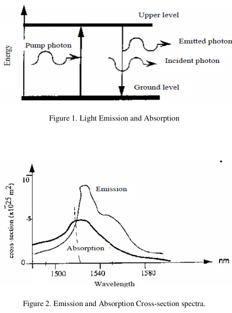
This transition is triggered by an incident photon from an input signal which is to be amplified. The emitted photon will have the same wavelength and phase as the incident photon. They are synchronous and coherent to each other. This is the laser effect. In Optical amplifiers, there is no feedback and all the energy required to invert the ion population is supplied by a powerful source to achieve population Inversion. In case of fiber amplifiers this source is optical (a laser) source and called as pump. The large population of excited ions is caused to reach to maximum gain. The signal and pump wavelengths depend on the emission and absorption aptitude of the doping ion. To achieve amplification the emission must be larger than the absorption at signal wavelength.
Figure 1. Light Emission and Absorption
Figure 2. Emission and Absorption Cross-section spectra.
As seen in Figure 2. the emission cross-section at 1550 nm is larger than absorption, thus the signal will be amplified. On the other hand, at pump wavelength (1480 nm) the erbium is only absorbed and therefore pumping will be efficient.
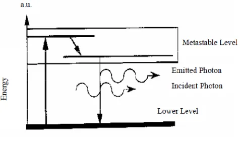
The erbium ions have more than two energy levels, as shown in Figure 3.
Figure 3. Energy level Diagram
The lowest energy level is the ground level.
The second level (the Meta stable level) is quite stable and average lifetime of an erbium ion is 10ms.The third level is just the opposite: an erbium ion pumped into this level will transit very quickly to the metastable level, without emitting any photon. This is a non-radioactive decay. There are two approaches to pump an Erbium ion into the metastable level.
3.1 PUMPING AT 980 nm BANDWIDTH
This pumping scheme was studied since the absorption of Erbium at 980 nm is higher than 15oo nm, consequently the pump efficiency is greater [6, 7].However 980 nm pumping suffers a high loss in the silica fiber [1,9].The high energy of the pumped photons allows the erbium ions of the metastable state to be excited into another upper energy level as shown in figure 4.The ion decay to the pump level without emitting any photon, and then metastable level [3,8].
Figure 4. ESA in a 4 level model
3.2 PUMPING AT 1460-1500 nm BANDWIDTH
Taking into account of the emission and absorption spectra of the erbium ion (Figure 2), the pumping band is 1480-1500 nm and the signal band is 1520-1570nm. In this case ESA can’t occur since Erbium ion is pumped into metastable level and also can’t reach any higher energy level [8] . Using advantage of the absence of excited state absorption and low loss at pump wavelength, the 1460-1500 nm pumping band is most appropriate bandwidth. The optimum signal wavelength for DEDFA has been found to be 1554 nm when a 1480 nm pump wavelength is used [10].Erbium glass showing pump wavelengths at 520nm (Desurvire,19870),620 nm (Mears,1987),800 nm (Mears et al.,19880),980 nm (Liaw et al.,1997) and 1480 nm(Galba et al.,1992) have been successfully demonstrated.
Figure 5. Two level model
Availability of pump laser diodes for 980 and 1480 nm; these pump wavelengths are widely deployed (Franz and Jain, 2000).While 1480 nm pump gives better power conversion efficiency as compared to 980 nm band(Desurvire,1994).
4. Configurations of EDFA
It discusses the different configurations of the EDFA and its effect on the NF and gain amplifier. EDFA configuration divided into stages and passes as follows.
4.1 One stage EDFA
One stage EDFA configuration which means only one EDFA that works as an active area. The one stage can be single pass or double pass configuration as shown in Figure.6
4.1.1 Single Pass
The basic SP-EDFA) module or configuration compromises one or two pump laser diode (LD) modules and also one or two WDM to collect the light with pump power, input and output Isolators and active medium (EDF).This configuration is flexible and clamped gains can be tuned in the range of 13.5 to 31.5 dB.
This method has some advantages such as grating resonance wavelengths can be tuned by bending the fiber section that contains the grating. It was observed the NF nad Gain values depend on the pumping configurations and produced optimum result at bidirectional pumping. Population inversion in EDFA was controlled by varying injected pump power.
Bidirectional pumping results best combination of Gain and NF of EDFA.The have taken SP-EDFA with a chirped fiber Brag grating (CFBG) to compensate attenuation and dispersion as well as considering the high gain and low NF by very low remote pump power. The numerical results play an remotely pumped SEDFA for the long haul ofcs (Nadir at al., 2007b)
4.1.2 Double pass
The basic double pass (DP EDFA) is a state in which signal will pass two times through the active medium, the EDFA as shown in figure 6b.Theoritically double pass method will enhance the gain twice as compared to the single pass(Desurvire,1994). Double pass configuration by using a single commercial EDFA for S band application as well as Amplifier spontaneous emission (Rosolem at al.,2008).
It was observed that the gain is not flat which may require a gain flattening device for gain equalization. Improved the NF of an EDFA with double pass configuration. Improved the NF of an EDFA with double pass configuration (Zhang et al, Ho et al., 2005). Naji et al., 2006a proposed an amplifier than 20 Db for small signals less than -23dBm with pump power 10Mw.
Figure 6.(a) One stage Single Pass (b) One stage Double pass
4.2 Two Stage EDFA
Two stage EDFA configurations can be double pass, triple pass or quadruple pass as shown in Figure.7
4.2.1 Double Pass
In Belal et al. (2011) author proposed a novel at low single power of -30 dBm is able to achieve gain up to 32.64 dB and NF of less than 5Db.Four types of L band silica based EDFA are experimented.1.Type I: Conventional forward pump.2.Type II: Conventional backward pump.3.Type III: Unpumped EDF section before forward pump.4.Type IV: Unpumped EDF section before backward pump .The result shows that the type III got the higher gain of 22 dB and NF 5dB.
4.2.2 Triple Pass
In khairil (2004) authors have proposed new high gain Erbium doped fiber amplifier configured in dual stage triple pass amplification where the first stage amplifier provide single pass amplification. The gain value is achieved higher than 37Db at NF 4.86 dB. According to khairil et al. (2006), a maximum gain is 51.72 dB and NF of 6.1 .The first stage EDFA combines C and L band amplification, and the second stage only amplifies L band signals.
The signal gain and NF obtained more than 24 Db and and less than 6Db.While in Suleiman et al.92004d, 2006) the clamped gain about 22 Db with low noise NF and gain is maintained below 5 and 6 Db respectively. In Tsair et al. (2008) a total of five different configurations of L-band EDFAs of high gain and low NF are examined and compared.
4.2.3 Quadruple Pass
In Sulaiman et al. (2004f); authors have proposed amplifier which achieve flat gain output at33.5 dB. The gain is 13.5 Db higher than that of the SP system with only 84MW 980 nm pumping power and the NF at flat gain region varies from 6.9 to 11.5 dB .Three dual pumped double pass EDFA systems are considered and compared performances in terms of NF 7Db is achieved for -50dBm signal power at 1550nm by using fiber loop back incorporated with tuneable band pass (Ali et al.2009).
4.3 Three Stage EDFA
The three stage EDFA configuration three EDFs that are working as active areas. It represented as follows; triple-pass with single triple-passes three times on EDF configuration as shown in Figure 8. Theoretical investigation has been done of a two pump, three stage L-band EDFA was based on a reliable numerical model (Zhi et al.2003).
Chin feng and Likran (2007) presented an idea of using residual pump power for implementation of low noise and high gain L-band EDFA by using a single pump power for implementation of low noise and high gain L-band EDFA by using a single pump laser and -30dBm signal power for all experiments (Chin et al.,2007). The gain and NF of EDFA system got a gain about 27 dB and NF about 6 to 7 dB.From the previous work it is clear that pump power plays very important role. Which have effect on gain &NF. Optimising pump power is important in order to get higher gain and low noise figure.
Referring to figure 9 for the increment of pump power from 5 to 14 MW, signal gain increases from 8.73 to 12.02 dB and NF decreases from 5.49 to 4.65dB. On the other hand, for the increment of pump power from 14 to 60 MW, signal gain increases from 12.02 to 13.54 dB and NF decreases from 4.65 to 4.35 dB.These result clearly shows that increment of gain and decrement of NF are very low with respect to the increment of pump power of 14 MW.Therefore the pump power of 14MW is chosen as the optimum pump power, because pump power exceeding 14MW has no high impact on the gain & NF of 10m long EDFA.
5. Conclusion
The use of OFCS generally allows for the transmission of large amounts of data at high speeds for long distance transmission. A detailed investigation of EDFA was given in three principal levels; first is the EDFA with WDM and DWDM technique in order to achieve higher bit rates. Second level is the Theoretical analysis of EDFA, where it is necessary to understand the physical meaning behind the amplification. The third level is the presentation of various configurations and their performance parameters related to different structures. These parameters need to be controlled to get higher gain and lowest NF.By increasing the total pump power, the transmission distance can be increased. On the other hand increasing the total injected pump power increases the non-linear effects of the transmission fiber, which degrades the system performance. Finally researches are expected to focus on reducing the noise figure at high pump powers.
References
[1] Paul Urguhart, “Theory of Erbium-doped Fiber Amplifiers”(BT Laboratories, Mortlesham Health.IP5 7RE).
[2] Emmanuel Desurvire, “Erbium-doped Fiber Amplifiers principles and applications”, A Wiley Interscience Publication.
[3] John A. Buck, “Fundamentals of Optical Fibers” (Wiley 1995).
[4] N.S.Bergano, Y.Yoshida, T.Kawazawa....etal,“9000km, 5Gbs/s NRZ transmission experiment using 274 EDFA” Paper PD 11,1992.
[5] S.Wen&S.chi,“Distributed Erbium-Doped Fiber Amplifiers with stimulated Raman Scattering” IEEE PTL,v.4(2),p 189-192.
[6] Donathan R. Armitage,“ Three-level Finber laser amplifier a Theoritical model” (Applied optics Vol. 27 No:23 December,1998).
[7] E Desurvire,“Recent advances in erbium doped fiber amplifiers at 1.5µm”OFC’90,fai,1990.
[8] A.A.M Saleh,R.M.Jopson …et al.“Modeling of gain in EDFAs”.IEEE PTL,v.2(10),p714-717.1990.
[9] S.T.Davey D.L Williums & B.J.Ainslie,“Distributed Erbium Doped Fiber for lossless link application”,OFC’91,FA 8,P 200,1991.
[10] K.Rottwitt,J.HPovlsen,T.Rasmussen, Optimum signal wavelength for a Distributed Erbium Doped Fiber Amplifier”,IEEE PTL,v.4(7),p 714-717,1992.
[11] Ali S, khaled AS,Al-khateeb..at all, “A new Erbium Doped Fiber Amplifier.J.Appl.Sci.Info.,9(15)2489-2500,2009.
[12] Desurvire E,“High gain erbium-doped fiber travelling wave fiber amplifier.Opt.Lett.,12:888-890,1997.
Authors
Dipika Pradhan is a Assistant professor at Electronics and Telecommunication Department, RSSOER, JSPM, pune. Pursuing PHD in SVNIT, Surat in Electronics engineering Department. She is specialized in Electronics and communication engineering. She published some of the research article in optics and sensor networks.