Management Components and Tools For
Distributed Control Systems
1
Sanjat Kumar Mishra,
2Sarojini Sethi,
3Mihir Narayan Mohanty
1,2Seemanta Engineering College, Jharpokharia, Mayurbhanj, Odisha, India
3ITER, SOA University, Bhubaneswar, Odisha, India
Abstract
The use of computer assisted software tools are gaining momentum in the recent years. In this era, where software tools and systems dominate many aspects of the design process, automation and control domain has no longer been an exception. These papers considers application level software tool for automated
systems. The work define a systematic approach to specification,
methodology, and prototype design of an application tool that is capable of providing services to the proposed management layer (ML)functionally for DCS(Distributed Control Systems) design applications. The tool is designed based on a layered model, which would make it easy to extend the existing DCS systems by
accommodating future modifications. The developed platform is modular and flexible which utilises the benefit of object oriented
and client server approach respectively. The utility of the developed platform is demonstrated through an experimental study.
Keywords
Distributed Control Systems, Management Layer, DCA, CCA
I. Introduction
The use of computer assisted software applications and tools are gaining momentum in the recent years [1]. As a result, design and development of application software has been the primary
domain in the research field of Computer Science and Information
technology. Broadly the application software are classified into two categories i.e., general purpose application software (for example Excel, Visual Basic, and so on), and application software for the system design [2]. The later types of software are software which are used to design and validate a physical system or architecture utilising governing fundamental laws and principles. The examples are solid works, Matlab/Simulink, NS2 and so on. Regardless of their nature, apparently, these software are designed and developed using the computers[3]. This research
work concentrates on specification requirements of an application
tool for the design, analysis and validation of Distributed Control
Systems (DCS) [3]. Ideally, DCS, a research field under the
area of industrial automation and control system, is regarded as control architecture [4]. The advantage of Distributed Control
Architecture (DCA) over its counterpart CCA is significant [5]. The work presented here is the specification requirements and various aspects of a management layer (ML) that is defined in
terms of an application tool that will be able to design and validate the DCS architecture. The ML integrates simulation environment which is considered as a system-level virtual environment. Figure 1 illustrates the schematic of both the architectures. The circle represents the node containing a microprocessor (or a PLC) along with other interfacings and memory devices. It is clear that the
node connects to the field devices in two different ways. Also,
notice how the task has been distributed among the nodes in DCS architecture. At the schematic level it looks very simple, however,
at the atomic level there is a significant difference between the
DCA and CCA.
Fig. 1: The two fundamental types of control architectures: (a) Centralised Control System, and (b) Distributed Control Systems. NX: Nodes.
The research objective is to establish an approach for the integration
of a simulation environment for the design of Distributed Control Systems (DCS) for real-time automation applications [6]. It is observed that the performance of the DCS design processes can be improved by the use of second software at the top of the conventional system level software tool (SLST). This top-level ware can be developed and realized in terms of a simulation tools. The applicability of simulation environment in the DCS systems
is tremendous and is considered as an additional requirement in
order to improve the performance of the DCS design processes. The simulation platform not only would validate the DCS systems but also reduces the design time compared to conventional method. The simulation tools available for other applications are PS-ENGINE, ISaGRAF, Mathematica, UML,etc.
II. Introduction to Management Layer
The design and implementation of distributed control network
look into four major elements as described below (Fig. 2).
Target application platform called process plant/machine/
•
systems
Hardware for the design of physical network. Usually
•
they are processor, transceiver, communication media, I/O interfaces
Management tool
•
Host computer with operating system
•
A. Management Tool
In DCS design process management tools plays important role..
There are various ways of defining the characteristics features of for
the purpose of DCS design. Network management functions such
as Fault Management, Configuration Management, Performance
Management, Security Management, Systems Management, and so on were originally emerged from the data communication network. However, network management functions within the DCS environment are somehow different. Most of the
the management layer [7]. This dissertation work proposes the concept of a management layer on the top of the control protocol stack as shown in the Fig. 3.
Fig. 2: Elements Required for the Design and Implementation
of DCA (NMT/NST: Network Management Tool or Network Simulation Tool)
Fig. 3: The Incomplete Management Layer
A management tool embedding the characteristic features of
management functions should be flexible and capable of handling
DCS network of complex structures (e.g., Supervisory Control
and Data Acquisition). For the design of large network the
management tasks is supposed to be performed concurrently as shown in Figure 4. That means, management functions should span multiple workbenches with many machines. Management of control network is therefore geared toward (i) to reduce the design-time, (ii) modular architecture and iii) reusability. Architecture of this tool should be centred around a central database with many
clients that deal with specific management functions in order to achieve higher degree of freedom and efficiency. All clients would
be able to access the same database for concurrent design of DCS
architecture. The end results are, (i) efficient network operations, (ii) modular architecture, (iii) flexibility in design, (iv) quality of
service, (v) high productivity, (vi) easy to maintain and modify
as requirement changes (vii) improved control capability, (viii)
low lifecycle cost, (ix) improved design-build-installation-setup time, (x) reduce commissioning time, (xi) re-designability, (xii) programmability, and (xiii) reusability. Usually, management layer
defines itself as a separate layer and until now it claims to be as
the middleware.
B. Management Components
Control codes must be downloaded into the nodes (node is a processing element interfacing the network and I/O devices such as sensors, actuators, valves, switches, drives etc.), and must be
installed, configured (logically) and tested. The executable entity such as installation, configuration, testing, repairing, supervision
and control (ICTRSC) can be then referred as Network Management Functions (NMF) [8]. Management of DCS with the aid of NMFs as a single layer can be achieved by the use of applications tools known as Management Tool (MT). Of the network management tools currently available the architectures are based on centralised as illustrated in the Figure 4 and as a matter of fact, the design
efficiency is not optimal. It is not preferable to build one that
would be able to handle all network management tasks when the
question of the large control network is raised.
Fig. 4: Schematic of Conventional Network Management Activities for DCS
III. The Need For Simulation For DCS
In engineering design also using accurate mathematical models of the system the design engineers verify the desired physical parameters before its real design starts. The same principle persists in the DCS world. Note that the simulation idea is not new. However, what is new in this research is that there is no such platform available in DCS domain. Bearing in mind that the virtual design environment can greatly improve reliability and availability of a system (e.g. a networking system), the work undertaken is to formulate a systematic approach to design and develop a virtual simulation environment that can provide services to simulate the DCS architecture.
Virtual methods can help to shorten the design-to-validation cycle by enabling the users to correct errors and to identify optimized
implementation stage. This phase is known as prototype testing.
Even the implementation of final design can benefit from such a
computer-assisted optimization tool prior to its prototype testing followed by real design. Thus the goal of the simulation is to close the design loop by enabling design, validation, comparison of measurement with other data, diagnostics, and then re-design. The simulation can improve the capability by reducing the time of the design process. Simulation tool will play a similar role in the design of complicated DCS.
The proposed simulation tool which is a part of the management layer (ML) would provide the services in order to realise management functions that need to be embedded in the tool. The tool can be considered as a dedicated application platform within the DCS environment that is capable of performing the following
activities like generate and compile control code, download object
code into the DCS node, install the DCS node onto the network
or sub-network, bind and configure the nodes, logical connection as per control requirements, testing and controlling the network
and/or winking, setting, resetting, and diagnostics.
The objective of the research is also to establish an approach for the
integration of both the management and simulation environment for the design of Distributed Control Systems (DCS) for real-time automation applications within manufacturing and process industry [9]. In fact, in this design the management layer embeds
the simulation environment (Figure 5). This section describes the
characteristic features of the management and simulation tools to be designed for the DCS applications. It presents abstract level
specification for the proposed Management Layer (ML) and the
Simulation Tool (ST). The needed attributes to be presented here can serve as the backbone of the ML and ST.
Fig. 5: Management Layer Embeds Simulation Environment
IV. Software Design View
A growing interest in new design strategy is leading to component-based design of automation and control systems. IEC 61499 can be used to show how both events and data are passed between function blocks running in different devices, and how the function blocks respond to events and run internal algorithms. The idea emphasizes that software is organised as sets of co-operating components rather than as the integration of large custom-built
units of objects [11]. Control system design tools and products start to get benefits of this new approach. Rockwell has shown interest;
Siemens has recently introduced a new system called ‘Profinet/
CBA’ (component based automation) which is planned to have an IEC 61499 compliant mapping in a later release. The Industrial Automation Open Networking Alliance (IAONA) organisation has also published white papers mentioning interest in using the
standard particularly related to fieldbus devices [12].
The components, which are different types of code modules, are expressed with their structure and dependencies. The characteristic properties of components are that a component is a unit of independent deployment and it has no persistent state. Eventually, it is an entity, designed to perform a certain function or tasks that can be used to compose more complex entities for a given purpose. It has also an external interface to communicate with others called I/O functions. The I/O functions have three features: (a) physical
I/O; (b) the communication protocol; (c) logical connections. The
concept of component should be extended to the combination of hardware and software. No matter whether the components are
hardware or software, they have the common characteristics; (i)
each component should be visible in some forms (different types
of code); (ii) can individually and completely do one or more tasks
(e.g. a screw connects two parts, a capacitor can stop DC and pass
AC); (iii) can set up some relationship with other components in connection; co-operative; and (iv) It could be a part of whole
system or part of another component. First the system is studied
and the components are created by the use of objects already available within the object oriented programming language. A
component library is then developed. The components can be used
to design the virtual DCS. The fieldbus conformant middleware
can be used to link the physical network (Fig. 6).
The rule for decomposing a System Components Library
Component Design
Control Systems Design
Building and Managing
Tool Box
Install, managing and monitoring Fieldbus
Fig. 6: Components Based Design View Using Fieldbus for the Automated Systems
V. Virtual Network Components Hierarchy
The simulation tool is a kind of infrastructure for the virtual control
network. The identified components for this virtual network are
formulated based on the knowledge gained from the actual control networks. The derived formulation is composed of components,
holons and objects which are very much compatible to LON technology. Further, LCA object server is used in order to harmonize these components. It should be noted that the specification of requirements needs considerable attention on standardization,
methodology, and especially the underlying functionalities. The analysis and modelling of the whole operational characteristics
of the management layer of virtual DCS is needed in first place. In this context, fieldbus conformant component derivatives are
features while extracting underlying parameters and variables in terms of a knowledge-model that represents a very detailed
temporal and off-line behaviour [14], which further identifies the requisite services. Fig. 6 illustrates the developed components
hierarchy.
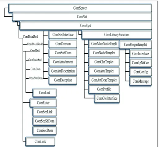
Fig. 7: Simulation Tool Component Hierarchy
For simplicity the word virtual is omitted from the description. For instance, the ComServer is a virtual server (Virtual Components Server) that resides on the top of other child components like ComNet: a network component manage the network activity, ComMainNode: a Node component that mimic the physical node (Neuron Chip) which is a server or hub node,ComNode: a General purpose node, ComDomain: Deals with network domain, ComSubDomain: a domain may have many sub-domains.
A. Virtual Protocol
The virtual protocol also supports different types of communications services such as unacknowledged, acknowledged, repeated, and priority. Under unacknowledged service the node send out messages on the network whenever the local application determines and it does not listen for responses from receiving nodes. This service provides the widest network bandwidth. Acknowledged service is used when it is important that a message be received at its intended destination. The repeated service is same as that of acknowledged service, but the message is sent a number of times determined at the time of node installation. Lastly, priority time slots on a channel can be allocated in order to improve the response time of critical packets. Only one node is assigned to a particular priority slot. Network management and applications software facilitates design, development and installation process. The installation
process requires logical connection between the devices, which
need to communicate to each other using installation tool.
B. Design
Decomposing a system into components is obviously complex. The framework for the design and implementation of
components-based DCS, which includes a set of defined rules for decomposing the system; Components libraries; A fieldbus and a set of
development tools. The basic principle of decomposing a system
into components is that each component individually implements at least a task. The interaction between components can be
event-driven or clock-based. The real DCS system can be configured
by the use of these components. Usual procedure as illustrated in the Fig. 8 will follow.
System analysis, decomposition, and task assignment
•
Logical binding; defining the relationship among components •
and drawing out the relationship chart
Testing the decomposed control system and finding out if it •
can meet the system requirements
Modifying the decomposed control system as necessary to
•
meet the final design requirements.
Fig. 8: Virtual Design Procedure Mimics the Real Design and Procedure
C. Virtual Processor
For a controller component, the main functions are inputting necessary messages, decision making according to the embedded control algorithms, outputting suitable control commands. In general, the control algorithms such as: mathematical process models, parameter and state estimation, lower-level feedback control, higher-level feedback control, adaptive control, fuzzy control, etc., can be embedded within a controller component. Some computation, such as: average, peak value, etc., can be done within the sensor component. Simple control algorithms can be embedded within the actuator components, like those implemented
in a PLC controller. The work undertaken by Xie et.al, [15-17] in
the content of formulating a virtual processor is adopted [18].
VI. The Algorithm and Built-Up Process
Simple representative network containing three nodes was built
using the software objects created. This is a four step procedure.
Fig. 9 illustrates the ingredients and design process of the sensor holons. It also illustrates schematic diagram of build-up
connections with regard to pre-defined control algorithm that is
described in Fig. 10 and Fig. 11.
nodes, however, it is possible to integrate hundreds of nodes depending upon the need of the control systems. For example, the control network of a mobile robotic system might contain nodes in the order of ten and might have logical connections in the order of one thousand. It was assumed that a physical connection of the network was ready before the downloading operation of the image was made. It is worth to mention that, the physical connections vary (whether peer-to-peer, master-slave etc.) with
respect to different types of fieldbus systems.
Fig. 9: The ingredients and design process of the sensor holon
– A four step procedure; (a) Look the practical control system,
create a database, create image, (b) inherit and embed into the control sensor module (c) interconnect the hardware and software database pointer in terms of virtual component (d) generate sensor holon)
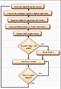
Fig. 10: Test Algorithm
Fig. 11: A Schematic Diagram Showing the use of Holons for Building up a Typical Virtual DCS Network
VII. Achieving Connectivity Validation
Any kind of control network has two types of connections,
namely; physical connection and logical connection. The physical
connectivity is realized through transceivers and communication links and the logical connectivity is established using conventional
method. It should be noted that the configuration of logical connectivity depends upon the control requirement of the target
system. Making physical connection is a challenge. However, logical connections in a control network are susceptible to error.
Without exact logical configuration control task is not feasible. In a networked system of complex nature, it is very difficult to
guarantee the logical connectivity among the variables that are
defined at the application layer of the communication protocol
stack. In a distributed system of thousand nodes with multiple
logical connections, it is not only difficult but also time consuming
in order to detect and isolate an illogical connection. The simulation software overcomes all such problems by designing a virtual network before the real design begins. As a result DCS validation
was achieved. The approach offered another level of flexibility in
the design process of the DCS.
VIII. Conclusion
The objective of this research was to explore the applicability of a
simulation platform for control and physical, logical and temporal
validation of DCS. The study defines a systematic approach as regards to specification, methodology and prototype design of
an application tool that is capable of providing services to the proposed management Layer(ML) functionality for DCS design applications. The tool is also designed based on a layered model, which would make it easy to extend the existing DCS systems
by accommodating future modifications. In order to meet the objective, we use an IBM compatible PC platform, Windows
7 OS, Visual Basic programming language, UML_start and
LonWorks Technology. Emphasis was also given on specification requirements. The utility of the developed platform is demonstrated
References
[1] J. A. Stafford, A. L. Wolf,"Architecture-Level Dependence Analysis for Software Systems", J. of Software Engineering
and Knowledge Engineering, 11(4), pp. 431–453, August
2001
[2] N. P. Mahalik, Sung Dong Kim, B H Ahn,"Specification requirement of temporal HILS environment for RCP of DMS, IEEE Int’l Conf. on Mechatronics, 2005. ICM ‘05, pp. 705-710, July 2005
[3] P Brain.Gerkey,"Most valuable Player, A Robot Device Server for Distributed Control", In Proceeding of the IEEE RSJ Int’l Conf. on Intellegent Robots and systems (IROS 2001), pp. 1226-1231, Oct.-Nov. 2001
[4] J. A. Stafford, A. L. Wolf,"Architecture-Level Dependence Analysis for Software Systems", J. of Software Engineering
and Knowledge Engineering, 11(4): pp. 431–453, August
200
[5] Rosaura Palma-Orozco, Gisela Palma-Orozco, José de Jesús Medel-Juárez, José Alfredo Jiménez-Benítez,"An Approach
to Centralized Control Systems Based on Cellular Automata, Advances in Soft Computing, Springer Berlin / Heidelberg, vol. 63, pp. 187-191, 2009
[6] V. Sasha Ilyukhin, A. Timothy Haley, K. Rakesh Singh, A Survey of Automation Practices in the Food Industry, Food
Control, vol. 12(5), Elsevier Science, pp. 285–296, July
2001
[7] N.P.Mahalik, J.Ryu, B.H.Ahn,"Simulation integrated management layer for real-time embedded DCN", Vol. 28,
Iss. 5, June 2006, pp. 508-522
[8] L. Raman,"OSI systems and network management", ADC Telecommun. Inc., Minneapolis, MN, Communications
Magazine, IEEE, Vol. 36, Iss. 3, pp. 46-53, 1998
[9] N.P.Mahalik, Editor, Book- Fieldbus Technology, Industrial Network Standard for Real-time Distributed Control, Springer Verlag, Germany, 2003.
[10] Xu Bin, Qian Depei, Lu Yueming, Wang Lei,"An active network-based network management framework", Communication Technology Proceedings, Int’l Conf. Vol.
1, pp. 95-100, 2000
[11] J.L.M. Lastra, L. Godinho, A. Lobov, R. Tuokko,"An IEC 61499 application generator for scan-based industrial controllers, 3rd IEEE Int’l Conf. on Industrial Informatics,
pp. 80 – 85, Aug. 2005
[12] Chen Gang, Ye Dong, Che Rensheng,"Developing Trend of Industrial Fieldbus Control System", 8th Int’l Conf. on
Electronic Measurement and Instruments, pp. 1-765 - 1-768,
Aug. 16 2007-July 18 2007
[13] Gunther Rogoll, Ren Kitchener,"Fieldbus Testing with Online Physical Layer Diagnostics", Internal report (TDOCT-1107_
USA), P+F fieldbus technology, 2006
[14] Rajagopalan Srinivasan, M. S. Qian,"Off-line Temporal
Signal Comparison Using Singular Points Augmented Time Warping", Ind. Eng. Chem. Res., 44 (13), pp 4697–4716,
2005
[15] N. Mahalik, C. Xie, J. Pu, P.R. Moore,"Virtual distributed
control systems: A components-based design method for mechatronic systems, Assembly Automation, Emerald Group
Publishing Limited", Vol. 26, Iss. 1, pp. 44 – 53, 2006
[16] C. Xie,"Component-image based methodology for the design of distributed control systems", De Montfort University, Leicester, PhD thesis, 1999.
[17] Juncao Li, Fei Xie, Huaiyu Liu,"Guiding Component-Based
Hardware/Software Co-Verification with Patterns", In Proc.
of 33rd EUROMICRO Conf. on Software Engineering and Advanced Application (SEAA), 2007.
[18] Matthew Simon, Graham Bee, Philip Moore, Jun-Sheng Pu, Changwen Xie,"Modelling of the life cycle of products with
data acquisition features", Computers in Industry, Vol. 45,
Iss. 2, June 2001, pp. 111-122.
Dr. Mihir Narayan Mohanty is presently working as an Associate Professor in the Department of Electronics and Communication Engineering, Institute of Technical Education and Research, Siksha ‘O’ Anusandhan University, Bhubaneswar, Odisha.
He has published over 150 papers in
International/National Journals, Book Chapters, and Conferences along with
approximately 25 years of teaching
experience in UG and PG level. He is the active member of many professional societies like IEEE, IET, IRED, EMC & EMI Engineers India, ISCA, ACEEE, IAEng etc. Also he is a Fellow of IE (I) and IETE. He has received his M. Tech. Degree in Communication System Engineering from Sambalpur University, Sambalpur, Odisha. Also he has done his Ph.D. work in Applied Signal Processing. He was working as Associate Professor and Head in the Department of Electronics and Instrumentation Engineering, Institute of Technical Education and Research, Siksha O’ Anusandhan University, Bhubaneswar, Odisha. His area of research interests includes – Applied Signal and Image Processing, Digital Signal/Image Processing, Biomedical Signal Processing, Microwave Communication Engineering and Bioinformatics. He has worked as Guest lecturer in many universities. Simultaneously has given many invited talks. He has reviewed many Springer and IEEE based conference papers as well as for some International Journal Papers. Currently four research scholars along with 4 number of PG students are under his guidance on Signal, Image & Speech Processing and Communication Engineering. Some students are working under his guidance for research work in