e-ISSN: 2278-067X, p-ISSN: 2278-800X, www.ijerd.com
Volume 8, Issue 8 (September 2013), PP. 47-52
A DC–DC Boost Converter for Photovoltaic Application
G.kranthi Kumar
1, Ch.Sampath Kumar
2, D. Kumara Swamy
31Pg student Warangal india, 2Assoc.prof Warangal indin, 3Assoc.Prof & HOD Warangal , india
Abstract:- Within the photovoltaic (PV) power-generation market, the ac PV module has shown obvious growth. However, a high voltage gain converter is essential for the module’s grid connection through a dc–ac inverter. This paper proposes a converter that employs a floating active switch to isolate energy from the PV panel when the ac module is OFF; this particular design protects installers and users from electrical hazards. Without extreme duty ratios and the numerous turns-ratios of a coupled inductor, this converter achieves a high step-up voltage-conversion ratio; the leakage inductor energy of the coupled inductor is efficiently recycled to the load. These features explain the module’s high-efficiency performance.
Index Terms:- AC module, coupled inductor, high step-up voltage gain, single switch.
I.
INTRODUCTION
Photovoltaic (PV) power-generation systems are becoming increasingly Important and prevalent in distribution generation systems. A conventional centralized PV array is a serial connection of numerous panels to obtain higher dc-link voltage for main electricity through a dc–ac inverter. Many prior research works have proposed a single-stage dc–ac inverter with fewer components to fit the dimensions of the bezel of the ac module, but their efficiency levels are lower than those of conventional PV inverters.
When installing the PV generation system during daylight, for safety reasons, the ac module outputs zero voltage. The solar energy through the PV panel and micro inverter to the output terminal when the switches are OFF.
When installation of the ac module is taking place, this potential difference could pose hazards to both the worker and the facilities.
A floating active switch is designed to isolate the dc current from the PV panel, for when the ac module is off-grid as well as in the non operating condition. This isolation ensures the operation of the internal components without any residential energy being transferred to the output or input terminals, which could be unsafe.
The micro inverter includes dc–dc boost converter, dc–ac inverter with control circuit. The dc–dc converter requires large step-up conversion
from the panel’s low voltage to the voltage level of the application. The converters by increasing turns ratio of coupled inductor obtain higher voltage gain than conventional boost converter. Some converters successfully combined boost and fly back converters, since various converter combinations are developed to carry out high step-up voltage gain by using the coupled-inductor techniques.
By combining active snubber, auxiliary resonant circuit, synchronous rectifiers, or switched- capacitor-based resonant circuits and so on, these techniques made active switch into zero voltage switching (ZVS) or zero current switching (ZCS) operation and improved converter efficiency.
1.1 SCOPE OF THE PROJECT
The scope of this project is to converter that employs a floating active switch to isolate energy from the PV panel when the ac module is OFF; this particular design protects installers and users from electrical hazards. Without extreme duty ratios and the numerous turns-ratios of a coupled inductor, this converter achieves a high step-up voltage-conversion ratio; the leakage inductor energy of the coupled inductor is efficiently recycled to the load.
1.2 EXISTING SYSTEM
A conventional centralized PV array is a serial connection of numerous panels to obtain higher dc-link voltage for main electricity through a dc–ac inverter. Unfortunately, once there is a partial shadow on some panels, the system’s energy yield becomes significantly reduced.
1.3 EXISTING SYSTEMS TECHNIQUE
successfully combined boost and flyback converters, since various converter combinations are developed to carry out high step-up voltage gain by using the coupled-inductor technique.
1.4 PROPOSED SYSTEM
The proposed converter has several features: 1) The connection of the two pairs of inductors, capacitor, and diode gives a large step-up voltage-conversion ratio;
2) the leakage-inductor energy of the coupled inductor can be recycled, thus increasing the efficiency and restraining the voltage stress across the active switch; and
3) the floating active switch efficiently isolates the PV panel energy during non operating conditions, which enhances safety. The operating principles and steady-state analysis of the proposed converter are presented.
1.5 PROPOSED SYSTEM TECHNIQUE
The micro inverter includes dc–dc boost converter, dc–ac inverter with control circuit as shown. The dc–dc converter requires large step-up conversion from the panel’s low voltage to the voltage level of the application. The primary winding N1 of a coupled inductor T1 is similar to the input inductor of the conventional boost converter, and capacitor C1 and diode D1 receive leakage inductor energy from N1. The secondary winding N2 of coupled inductor T1 is connected with another pair of capacitors C2 and diode D2 , which are in series with N1 in order to further enlarge the boost voltage.
II.
PROJECT DESCRIPTION
2.1 METHODOLOGIES Module 1: INTRODUCTION
Module 2: OPERATING PRINCIPLES OF THE PROPOSED CONVERTER A. CCM Operation
B. DCM Operation
2.2 MODULE DESCRIPTION Module 1: INTRODUCTION
Photovoltaic (PV) power-generation systems are becoming increasingly important and prevalent in distribution generation systems. A conventional centralized PV array is a serial connection of numerous panels to obtain higher dc-link voltage for main electricity through a dc–ac inverter. Unfortunately, once there is a partial shadow on some panels, the system’s energy yield becomes significantly reduced. An ac module is a micro inverter configured on the rear bezel of a PV panel this alternative solution not only immunizes against the yield loss by shadow effect, but also provides flexible installation options in accordance with the user’s budget.
Many prior research works have proposed a single-stage dc–ac inverter with fewer components to fit the dimensions of the bezel of the ac module, but their efficiency levels are lower than
those of conventional PV inverters.
Fig 1. Potential difference on the output terminal of non floating switch micro inverter.
Module 2: PROPOSED CONVERTER
The operation of the proposed converter is compressed with the coupled inductor T1, T1 is represented as a magnetizing inductor Lm, primary and secondary leakage inductors Lk 1 and Lk 2 , and an ideal transformer. In order to simplify the circuit analysis of the proposed converter, the following assumptions are made.
1) All components are ideal, except for the leakage inductance of coupled inductor T1, which is being taken under consideration. The on-state resistance RDS(ON) and all parasitic capacitances of themain switch S1 are neglected, as are the forward voltage drops of diodes D1 & D3 .
2) The capacitors C1 & C3 are sufficiently large that the voltages across them are considered to be constant. 3) TheESRof capacitorsC1 &C3 and the parasitic resistance of coupled inductor T1 are neglected.
4) The turns ratio n of the coupled inductor T1 windings is equal to N2 /N1.
A. CCM Operation
The CCM operation is the means of Continuous Conduction mode in this transition interval, the magnetizing inductor Lm continuously charges capacitor C2 through T1 when S1 is turned ON. The current flow path is switch S1 and diode D2 are conducting. CCM operation mode has few mode operation to express the operating of the T1,S1,C1,C2,D1,D2.
Mode I: when the mode operation is started in between the time interval (t0-t1) the transition interval, the magnetizing inductor Lm continuously charges capacitor C2 through T1 when S1 is turned ON. Current iLm is decreasing because source voltage Vin crosses magnetizing inductor Lm and primary leakage inductor Lk1 magnetizing inductor Lm is still transferring its energy through coupled inductor T1 to charge switched capacitor C2 , but the energy is decreasing the charging current iD 2 and iC2 are decreasing. The secondary leakage inductor current iLK2 is declining as equal to iLm / n. Once the increasing iLk1 equals decreasing iLm at t = t1, this mode ends.
Fig 2.A
Fig 2a.
When the time period (TS) is operating at the time of t1 – t2interval, during this interval the source energy Vin is series connected with N2, C1 , and C2 to charge output capacitor C3 and load R; meanwhile magnetizing inductor Lm is also receiving energy from Vin . The current flow path where switch S1 remains ON, and only diode D3 is conducting. The iLm, iLk1 , and iD3 are increasing because the Vin is crossing Lk1 , Lm, and primary winding N1 ; Lm and Lk1 are storing energy from Vin ; meanwhile Vin is also serially connected with secondary winding N2 of coupled inductor T1 , capacitors C1 , and C2 , and then discharges their energy to capacitor C3 and load R. The iin , iD 3 and discharging current |iC1 | and |iC2 | are increasing. This mode ends when switch S1 is turned OFF at t = t2 .
Mode III: When the time period (TS) is operating at the time of t2 – t3interval, during this transition interval the secondary leakage inductor Lk2 keeps charging C3 when switch S1 is OFF. The current flow path where only diode D1 and D3 are conducting. The energy stored in leakage inductor Lk1 flows through diode D1 to charge capacitor C1 instantly when S1 is OFF. Meanwhile, the energy of secondary leakage inductor Lk2 is series connected with C2 to charge output capacitor C3 and the load. Because leakage inductance Lk1 andLK2 are far smaller than Lm, iLk2 rapidly decreases, but iLm is increasing because magnetizing inductor Lm is receiving energy from Lk1 . Current iLk2 decreases until it reaches zero; this mode ends at t = t3 .
Mode IV: When the time period (TS) is operating at the time of t3 – t4 interval, during this transition interval the energy stored in magnetizing inductor Lm is released to C1 and C2 simultaneously. The current flow path through only diodes D1 and D2 are conducting. Currents iLk1 and iD1 are continually decreased because the leakage energy still flowing through diodeD1 keeps charging capacitor C1. The Lm is delivering its energy through T1 and D2 to charge capacitor C2 . The energy stored in capacitor C3 is constantly discharged to the load R. These energy transfers result in decreases in iLk1 and iLm but increases in iLk2 . This mode ends when current iLk1 is zero, at t = t4 .
Fig 2c
Mode V: When the time period (TS) is operating at the time of t4 – t5 interval, during this interval the only magnetizing inductor Lm is constantly releasing its energy to C2 . The current flow path which only diode D2 is conducting. The iLm is decreasing due to the magnetizing inductor energy flowing through the coupled inductor T1 to secondary winding N2 , and D2 continues to charge capacitor C2 . The energy stored in capacitor C3 is constantly discharged to the load R. This mode ends when switch S1 is turned ON at the beginning of the next switching period.
B. DCM Operation
The discontinuous conduction mode (DCM) operation are presented in this section. depicts several typical waveforms during five operating modes of one switching period.
When the time period (TS) is operating at the time of t0 – t1interval, during this interval the source energy Vin is series connected with N2, C1 , and C2 to charge output capacitor C3 and load R; meanwhile, magnetizing inductor Lm is also receiving energy from Vin. The current flow path is which depicts that switch S1 remains ON, and only diode D3 is conducting. The iLm, iLk1 , and iD3 are increasing because the Vin is crossing Lk1 , Lm, and primary winding N1 ; Lm and Lk1 are storing energy from Vin ; meanwhile, Vin also is serially connected with secondary winding N2 of coupled inductor T1 , capacitors C1 , and C2 ; then they all discharge their energy to capacitor C3 and load R. The iin , iD 3 and discharging current |iC1 | and |iC2 | are increasing. This mode ends when switch S1 is turned OFF at t = t1 .
When the time period (TS) is operating at the time of t1 – t2interval, during this transition interval the secondary leakage inductor Lk2 keeps charging C3 when switch S1 is OFF. The current flow and only diode D2 and D3 are conducting. The energy stored in leakage inductor Lk1 flows through diode D1 to charge capacitor C1 instantly when S1 is OFF. Meanwhile, the energy of secondary leakage inductor Lk2 is series-connected with C2 to charge output capacitor C3 and the load. Because leakage inductance Lk1 and LK2 are far smaller thanLm, iLk2 decreases rapidly, but iLm is increasing because magnetizing inductor Lm is receiving energy from Lk1 . Current iLk2 reduces down to zero, and this mode ends at t = t2 .
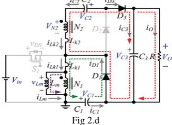
Fig 2.d
Currents iLk1 and iD1 are continually decreased because leakage energy still flowing through diode D1 keeps charging capacitor C1. The Lm is delivering its energy through T1 andD2 to charge capacitorC2 .The energy stored in capacitor C3 is constantly discharged to the loadR. These energy transfers result in decreases in iLk1 and iLm but increases in iLk 2. This mode ends when current iLk1 reaches zero at t = t3 .
When the time period (TS) is operating at the time of t3 – t4 interval, during this interval, only magnetizing inductor Lm is constantly releasing its energy to C2 and only diodeD2 is conducting. The iLm is decreasing due to the magnetizing inductor energy flowing through the coupled inductor T1 to secondary winding N2, and D2 continues to charge capacitor C2 . The energy stored in capacitor C3 is constantly discharged to the load R. This mode ends when current iLm reaches zero at t = t4s.
When the time period (TS) is operating at the time of t4 – t5 interval, during this interval, all active components are turned OFF; only the energy stored in capacitor C3 is continued to be discharged to the load R. This mode ends when switch S1 is turned ON at the beginning of the next switching period.
III.
SIMULATION RESULTS
Simulation Block Diagram
Simulation Results
IV.
CONCLUSION
Since the energy of the coupled inductor’s leakage inductor has been recycled, the voltage stress across the active switch S1 is constrained, which means low ON-state resistance RDS(ON) can be selected. Thus, improvements to the efficiency of the proposed converter have been achieved. The switching signal action is performed well by the floating switch during system operation; on the other hand, the residential energy is effectively eliminated during the nonoperating condition, which improves safety to system technicians. From the prototype converter, the turns ratio n = 5 and the duty ratio D is 55%; thus, without extreme duty ratios and turns ratios, the proposed converter achieves high step-up voltage gain, of up to 13 times the level of input voltage. The experimental results show that the maximum efficiency of 95.3% is measured at half load, and a small efficiency variation will harvest more energy from the PV module during fading sunlight.
REFERENCES
[1]. K. B. Park, G.W.Moon, andM. J. Youn, “Nonisolated high step-up boost converter integrated with sepic converter,” vol. 25, no. 9, pp. 2266–2275, Sep. 2010.
[2]. T. Umeno, K. Takahashi, F. Ueno, T. Inoue, and I. Oota, “A new approach to lowripple-noise switching converters on the basis of switched- capacitor converters,” in Proc. IEEE Int. Symp. Circuits Syst., Jun. 1991, pp. 1077– 1080.
[4]. Q. Zhao and F. C. Lee, “High-efficiency, high step-up dc–dc converters,” IEEE Trans. Power Electron., vol. 18, no. 1, pp. 65–73, Jan. 2003.
[5]. B. Axelrod, Y. Berkovich, and A. Ioinovici, “Switched-capacitor/ switched-inductor structures for getting transformerless hybrid dc–dc PWM converters,” IEEE Trans. Circuits Syst. I, Reg. Papers, vol. 55, no. 2, pp. 687–696, Mar. 2008.
[6]. L. S. Yang and T. J. Liang, “Analysis and implementation of a novel bidirectional dc–dc converter,” IEEE Trans. Ind. Electron., vol. 59, no. 1, pp. 422–434, Jan. 2012.
[7]. W. Li and X. He, “Review of non-isolated high-step-up dc/dc converters in photovoltaic grid-connected applications,” IEEE Trans. Ind. Electron., vol. 58, no. 4, pp. 1239–1250, Apr. 2011.
[8]. S. H. Park, S. R. Park, J. S. Yu, Y. C. Jung, and C. Y. Won, “Analysis and design of a soft-switching boost converter with an HI-Bridge auxiliary resonant circuit,” IEEE Trans. Power Electron., vol. 25, no. 8, pp. 2142– 2149, Aug. 2010.
[9]. G. Yao, A. Chen, and X. He, “Soft switching circuit for interleaved boost converters,” IEEE Trans. Power Electron., vol. 22, no. 1, pp. 80–86, Jan. 2007.