Analysis of Transverse Magnetic Modes in Microstrip Patch Antenna
T.Anu1 and V.Dinesh2
1PG Scholar, Department of ECE, Kongu Engineering College, Erode, India.
2Assistant Professor, Department of ECE, Kongu Engineering College, Erode, India.
Article Received: 01 March 2018 Article Accepted: 09 April 2018 Article Published: 28 April 2018
1. INTRODUCTION
Microstrip antennas offer the advantages of thin profile, light weight, low cost, and conformability to a shaped
surface and compatibility with integrated circuitry. In addition to military applications, they have become attractive
candidates in a variety of commercial applications such as mobile satellite communications, the direct broadcast
(DBS) system, the global positioning system (GPS), remote sensing and hyperthermia. This was led to extensive
research aimed at improving the impedance bandwidth of microstrip antennas in the last several years.
The basic form of the microstrip antenna, consisting of a conducting patch printed on a grounded substrate, has an
impedance bandwidth of 1-2%. One way of improving the bandwidth to 10-20% is to use parasitic patches, either in
another layer (stacked geometry) or in the same layer (coplanar geometry). However, the stacked geometry has the
disadvantage of increasing the thickness of the antenna while the coplanar geometry has the disadvantage of
increasing the lateral size of the antenna. It would therefore be of considerable interest if a single-layer single-patch
wideband microstrip antenna could be developed. Such an antenna would better preserve the thin profile
characteristics and would not introduce grating lobe problems when used in an array.
Indoor wireless links have intrinsic characteristics that affect the system performance, such as the multipath effect
that causes signal fading, and interference effect from adjacent cells that degrades the bit error rate. From the
physical layer perspective, one solution to combat these impairments is the use of directional antennas rather than
the traditional omnidirectional ones [1]. They have the ability to confine the power in certain directions instead of
scattering the power everywhere. As a result of less power loss toward unwanted directions, the multipath and
interference effects are reduced. Directional antennas can be single or dual/multi-beam. Dual/multi-beam antennas
are antennas that have more than one directive beam from a single aperture. These antennas are useful for indoor
wireless systems which require coverage of multiple areas [2], as they reduce the required number of antennas and
are found to improve the link quality [3], resulting in easier network deployment. A B S T R A C T
Transverse magnetic modes in microstrip patch antenna are analyzed. Two radiation beams off broadsides are obtained by operating the patch antenna at the higher order mode TM02 instead of the fundamental mode TM01 which radiates a broadside beam. Antenna bandwidth is broadened by using a U-slot technique. Rogers RT Duroid with the relative permittivity 2.2 is used as a dielectric substrate material with the thickness of 3.175mm. The proposed patch antenna is designed and simulated by using HFSS. The antenna frequency range is 5.18-5.8GHz with VSWR less than 2, with the impedance bandwidth of 11.8%. The antenna resonates at 5.2 GHz, which exhibits two radiation beam
Microstrip antennas have been widely used in many modern communication systems, because of its robustness,
planar profile, and low cost. Most of these antennas operate at their fundamental mode 𝑇𝑀01, which gives a
broadside beam [4]. Microstrip antenna operating at the higher order 𝑇𝑀02 mode has dual symmetric radiation
beams, with each beam directed at respectively [5][6]. It is well known that the major drawback of a microstrip
antenna is its narrow bandwidth. One of the popular techniques for broadening the patch antenna bandwidth is to
incorporate a U-slot on its surface as proposed in [7][8]. U-slot microstrip antenna operating at the 𝑇𝑀02 mode to
attain dual radiation beams with wideband performance is proposed. The U-slot inclusion on the patch’s surface
introduces asymmetry, which affects the radiation, such as pattern symmetry, pattern stability, cross-polarisation
level, and the direction of the beams [9].
In this paper, radiation characteristics of the microstrip patch antenna are analyzed for different transverse magnetic
modes and incorporating U-slot on the patch to attain wideband performance is proposed.
2. ANTENNA GEOMETRY
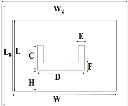
The proposed antenna geometry is shown in Fig. 1, where a coaxial-fed rectangular patch is printed over a Rogers
RT Duroid substrate of thickness 3.175mm and permittivity 4.4. A U-slot is cut on the patch’s surface, which is
mounted over the substrate of size Lg×Wg=67×74mm. The other side of the substrate is coated with metal, which is
the ground plane of the antenna. All the design parameters were calculated by equations that are explained in the
following sections and the calculations results of all dimensions are shown in Table I.
Fig. 1. Geometry of proposed U-Slot microstrip antenna
2.1. Calculation of patch dimension
Width of the patch can be calculated using the below formula [12]:
√ (1)
The value of the effective dielectric constant is given by:
* + (2)
Where h and W are the height and width of the substrate material for an antenna respectively.
Length of the patch can be calculated as follows:
√
(3)
The dL is the length extension due to the fringing field and can be calculated using the equation:
( )( )
( )( ) ( )
In general, the resonant frequency of rectangular patch antennas is calculated by using resonant length transmission
line or cavity models, together with equations for the effective dielectric constant and edge extension. The resonant
frequency fmn of a rectangular patch of width W and length L is given by
√ √([ ] * + ) (5)
2.2 Calculation of ground dimension
The ground dimension of an antenna can be calculated as follows:
Width of the ground is given as:
Wg =W+6h (6)
Length of the ground is given as:
Lg =L+6h (7)
2.3 Calculation of U-Slot parameters
Slot thickness E and F is given by:
(8)
Slot width D is given by:
( )
( ) (9)
Other parameters are calculated as:
( ) * + (11)
Where h is the thickness of the dielectric substrate.
( ( ) ) (
)
( ( ) ) ( ) ( )
Height of slot from base H is given as:
√ ( )[ ( )] (13)
2.4. Feeding technique & location
The common feeding technique used in microstrip patch antennas is coaxial feeding. The inner conductor of the
coaxial connector extends through the dielectric and is soldered to the radiating patch, while the outer conductor is
connected to the ground plane. The main advantage of this technique is that feed can be placed at any desired
location inside the patch in order to match with its input impedance. The impedance matching will depend on feed
point location on the patch. Feed point location in order to match 50ohm impedance is calculated using the
following equation:
Along the width of the patch:
( )
Along the length of the patch:
( )
Where √ ( )
√ ( )
( ) (18)
This equation provides only an approximation. Impedance matching was achieved after a lot of iterations and the
Table I: Design parameters of U-Slot
SPECIFICATION VALUES(mm)
Slot Width (D) 12
Slot Length (C) 28.25
Height of Slot from
Base (H)
2
Slot Thickness
(E=F)
2
3. PARAMETRIC STUDY
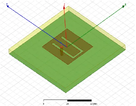
The proposed antenna is shown in fig.2. The overall size of the antenna is 67×74×3.175mm.The feeding method
used here is coaxial feeding. Due to substrate thickness, the increased probe length makes the input impedance
more inductive, leading to matching problems. The parameters that have the critical influence on the antenna
performance are chosen for parametric study. These parameters are L, W, C and H. To study their effects on the
antenna performance, the parametric study is carried out on the parameters mentioned above.
3.1. Patch with U-Slot
The proposed antenna consists of U-Slot incorporated on the patch is shown in fig. 2 which attains wide bandwidth
without adding the parasitic patch in another layer or in the same layer.
Fig. 2. U-slot Microstrip Patch Antenna
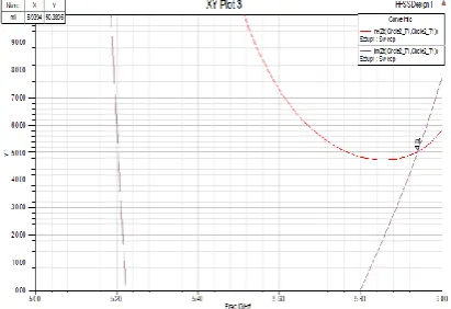
The wideband behavior is due to the fact that current along the edges of slot introduces an additional resonance
which in conjunction with the resonance of patch produces broadband frequency response characteristics. It is
important to note that, although, this is an electrically thick probe fed patch, there is no inductive component
associated with the input impedance is shown in fig.3.This is due to introduction of the slot in the patch which
Fig. 3. Impedance Characteristics of the proposed antenna
Fig. 4. Return loss of proposed antenna
Fig. 5. VSWR of the proposed antenna
Fig. 6. Gain of the antenna
1.00 2.00 3.00 4.00 5.00 6.00 7.00
Freq [GHz] -16.00 -14.00 -12.00 -10.00 -8.00 -6.00 -4.00 -2.00 0.00 d B(S t(w a ve p o rt _ T 1 ,w a ve p o rt _ T 1 )) HFSSDesign1 XY Plot 1
m 1
m 2 m 3 m 4
Curve Info
dB(St(w aveport_T1,w aveport_T1)) Setup1 : Sw eep
Name X Y
m 1 2.7789 -14.3521
m 2 5.1005 -15.2331 m 3 5.0402 -9.5731
m 4 5.1910 -9.4172
1.00 2.00 3.00 4.00 5.00 6.00 7.00
Freq [GHz] 1.25 2.25 3.25 4.25 5.25 6.25 7.25 8.25 9.25 10.00 VS W R t(w a ve p o rt _ T 1 ) HFSSDesign1
XY Plot 2
m1 m2
Curve Info VSWRt(w aveport_T1) Setup1 : Sw eep Name X Y
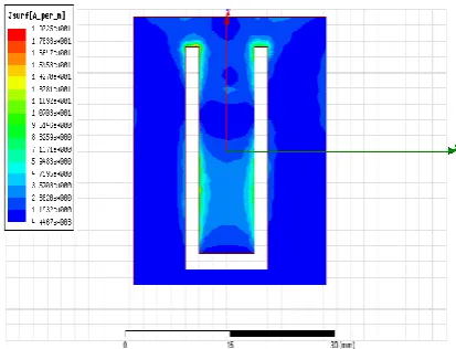
3.2. Mode of operation
Fig.7 shows the current distribution on the surface of a U-slot patch antenna. From the figure, it is observed that
dual mode is obtained by having a patch length L to be λd, where λd is the wavelength in the dielectric substrate.
According to the cavity model of the patch antenna [10], the current on the patch’s surface, has two maxima at
TM02. Therefore, for a U-slot to work effectively, it should intercept both current maxima. It is obvious that the
presence of two maxima on the patch indicates a λd resonator at the TM02 mode.
Fig. 7. Current distribution of the antenna at TM02 mode
4. CONCLUSION
A U-slot microstrip antenna operating at a higher order mode TM02 has been proposed and investigated. The
antenna has 11.3% bandwidth (5.17-5.81 GHz) with better impedance matching and exhibits dual radiation beams.
The proposed design is a desirable candidate for stationary terminals of various indoor wireless communication
networks.
REFERENCES
[1] Y. M. Tao and G. Y. Delisle, “Lens-fed multiple beam array for millimeter wave indoor communications,”
in Proc. IEEE AP-S Int. Antenna and Propag. Symp. Digest, Jul. 1997, pp.2206–2209.
[2] K. Li, M. Ingram, and E. Rausch, “Multi-beam antennas for indoor wireless communications,” IEEE
Trans. Comm., vol.50, no.2, Feb.2002.
[3] K. Carver and J. Mink, “Microstrip antenna technology,” IEEE Trans. Antennas Propag., vol. 29, no. 1, pp.
2–24, 1981.
[4] Y. T. Lo, D. Solomon, and W. F. Richards, “Theory and experiment on microstrip antennas,” IEEE Trans.
Antennas Propag., vol. 27, no. 2, pp. 137–145, Mar. 1979.
[5] J. R. James and P. S. Hall, Handbook of Microstrip Antennas. London, U.K.: Peter Peregrinus Ltd, 1989, p.
111.
[6] K. F. Lee and K. M. Luk, Microstrip Patch Antennas. London, U.K.: Imperial College Press, 2010.
[8] K. M. Luk, C. L. Mak, Y. L. Chow, and K. F. Lee, “Broadband microstrip patch antenna,” IET Electron.
Lett., vol. 34, no. 15, pp. 1442–1443, 1998.
[9] Awij A.R.Shaik Suhail Shaikh Sohail Ansari Danish Marwadi, “Wide Band Dual-Beam U-slot Microstrip
Patch Antenna”, International Journal for Scientific Research & Development| Vol. 5, Issue 03, 2017.
[10] K. Carver and J. Mink, “Microstrip antenna technology,” IEEE Trans. Antennas Propag., vol. 29, no. 1,
pp. 2–24, 1981.
[11] Ahmed Khidre, Kai-Fong Lee, Atef Z. Elsherbeni, and Fan Yang, “Wide Band Dual-Beam U-Slot
Microstrip Antenna,” IEEE Transactions on Antennas and Propagation, vol. 61, no. 3, March 2013.
[12] C. A. Balanis, Antenna Theory Analysis and Design, 2nd ed. Hoboken, NJ, USA: Wiley Inderscience,
2005, p. 814.