BLACK BOX FOR VEHICLES
P. Ajay Kumar Reddy
1, P.Dileep Kumar
2, K. Bhaskar reddy
3, E.Venkataramana
4,
M.Chandra sekhar Reddy
51,2,3,4,5(Assistant Professor, Department of ECE, Kuppam Engineering College/JNTUA/INDIA)
Abstract:––The main purpose of the paper is to develop a prototype of Black Box For vehicle diagnosis that can be installed into any vehicle. This prototype can be designed with minimum number of circuits. This can contribute to construct safer vehicles, improving the treatment for crash victims, helping insurance companies with their vehicle crash investigations, and enhancing road status in order to decrease the death rate.
Keywords:––Vehicle, Black Box, Microcontroller, Computer Interface
I.
INTRODUCTION
According to the World Health Organization, more than a million people in the world die each year because of transportation-related accidents [1]. In order to react to this situation, the black box system draws the first step to solve problem. Like flight data recorders in aircraft, "Black Box” technology can now play a key role in motor vehicle crash investigations [4]. A significant number of vehicles currently on the roads contain electronic systems that record in the event of a crash. That is why it is so important to have recorders that objectively track what goes on in vehicles before, during and after a crash as a complement to the was used. Subjective input that is taken usually from victims, eye witnesses and police reports. This system is mainly committed to two sections. The first one is how to detect and collect the information from the vehicle. The second is how to present the data to the user in a simplified way. To implement the first section many components and various types of sensors are used. While the second section was implementing by using the Embedded C programming. This programming helps in not only recording the data but also retrieving the data from microcontroller memory to an LCD to display it. In order to know which type of sensors to be installed into the vehicle various types of research are done and following ones are considered as the most important data that is needed after the accident: Belt status, Break status, Lane detection and CAN Failures. In this section we describe in section II the hard ware resources and in section III the software resources followed by the conclusion in section IV.
II.
HARDWARE RESOURCES
The hardware part consists of the components and the sensors used in the black box system. This part mainly collects the status of the sensors and stores it into the micro controller‘s EEPROM.
A. Sensors. 1) Proximity Sensor
A proximity sensor is used to detect the lanes in which the vehicle is travelling. A proximity sensor is a sensor able to detect the presence of nearby objects without any physical contact. A proximity sensor often emits an electromagnetic or electrostatic field, or a beam of electromagnetic radiation (infrared, for instance), and looks for changes in the field or return signal.
2) Ultrasonic sensor
Fig.1 Block diagram representation vehicle.
3) Pressure Sensor
A pressure sensor measures pressure, typically of gases or liquids. Pressure is an expression of the force required to stop a fluid from expanding, and is usually stated in terms of force per unit area. This pressure sensor is mainly used to find whether an accident has occurred or not.
4) Temperature Sensor
This sensor is mainly used to detect the temperature of the engine of vehicle. It detects two types of temperatures one is abnormal temperature and other is engine temperature.
5) Switches
To simulate the seat belt and break test IR jumpers are used. The jumpers are mainly used as loops of the circuit, using jumpers it forms a closed loop.
a) Belt sensor and seat belt
One push button is used to detect the place of the seat belt during the drive. The seat belt of the driver is only taken into consideration in this paper, but can be extended to include all the belts of the vehicle, depending on the traffic regulations of each country. The push button is placed on the seatbelt and gives logic 'zero' when the belt is used and logic ' I' when the belt is not placed by the driver.
b) CAN Test
CAN controllers are tested by using the IR Jumpers. The two CAN controllers present in the ARM Processor are tested to know the data flowing in the loop. The data which is passed to the ARM processor is passed to CAN controllers in order to communicate with the other devices.
B. Digital processing.
In order to control all these sensors and their inputs, a digital process can be used. As prototype a ARM micro controller is selected to control the black box. This will allow the control circuit to be realized by a minimum of circuits. For this prototype, the main need was a large EEPROM, to enable recording as much data is possible about the accident, and a large amount of inputs. Thus LPC 2129 is used because it has 16 kB on-chip Static RAM, 128 kB on-chip Flash Program Memory. Four channel 10-bit A/D converter, Two 32-bit timers, PWM unit, Real Time Clock and Watchdog, two UARTs, Fast I2C, two SPIs and other characteristics.
1) Micro controller’s Connections
The inputs to the microcontroller, which contain information about the accident, are distributed. The inputs to the microcontroller, which contain information about the accident, are distributed as follows: 1 for the belt sensor, 1 for the
Brake
Module
Seat belt
Belt
Temperature Sensor Ultrasonic SensorSensor
C A NB
U
S
L
P
C
2
1
2
9
LCD Proximity sensor
SENSOR
DC Motor CAN Bus CAN Bus EEPROM DC MOTOR DRIVER PWMRF RX
PC RF TX
lines. The LCD will show the user about the recorded data when the accident has occurred.
2) Micro Controller EEPROM
The AT24C02 provides 2048 bits of serial electrically erasable and programmable read-only memory (EEPROM) organized as256 words of 8 bits each. The device is optimized for use in many industrial and commercial applications where low-power and low-voltage operation are essential. The memory organization of AT24C02,2K SERIAL EEPROM: Internally organized with 32 pages of 8 bytes each, the 2K requires an 8-bit data word address for random word addressing.
3) Microcontroller’s Program
The main function of the microcontroller program is to take input samples from different ports. These samples are taken from the sensors installed in the vehicle. After that , each sensor sample is saved into the microcontroller’s EEPROM. After the accident all the data from the sensors is received by the microcontroller before it goes into the sleep mode. This data is used to analyzing the accident. The choice of the microcontroller's transmission protocol was the standard asynchronous format using 8 data bits, no parity bit and one stop bit with a 9600 baud rate. Since the complexity is in the interpretation of the data and not in the transmission, the need was for a format that guarantees minimum simplicity with maximum reliability. In addition, a MAX232 is used as an intermediary station, to connect the microcontroller to the serial port of the computer.
III.
SOFTWARE RESOURCES
After the hardware part of the Black Box system, it is now time to look at the software details and how the user is shown the data before and after the accident. The main details of the project are to receive the data serially, intercept and finally display the results to the user in a clear and simple way. For the software implementation, we deploy two software packages. First one is the Keil µVision 3.0. Second one is the Flash magic simulator. The Keil µVision Debugger accurately simulates on-chip peripherals (I²C, CAN, UART, SPI, Interrupts, I/O Ports, A/D Converter, D/A Converter, and PWM Modules) of ARM7device. Simulation helps to understand hardware configurations and avoids time wasted on setup problems. With simulation, we can write and test applications before target hardware is available. The system program written in embedded C using KEIL IDE software will be stored in Microcontroller. Keil development tools for the Microcontroller Architecture support every level of software developer from the professional applications engineer to the student for learning about embedded software development. The industry-standard Keil C Compilers, Macro Assemblers, Debuggers, Real-time Kernels, Single-board Computers, and Emulators support all ARM7 derivatives. The Keil Development Tools are designed to solve the complex problems facing embedded software developers. Flash magic is used to dump the code to microcontroller from PC. Flash Magic is a free, powerful, feature-rich Windows application that allows easy programming of Philips FLASH Microcontrollers. Build custom applications for Philips Microcontrollers on the Flash Magic platform! Use it to create custom end-user firmware programming applications, or generate an in-house production line programming tool. The Flash Memory In-System Programmer is a tool that runs under Windows 95/98/NT4/2K. It allows in-circuit programming of FLASH memories via a serial RS232 link. Computer side software called Flash Magic is executed that accepts the Intel HEX format file generated from compiler Keil to be sent to target microcontroller. It detects the hardware connected to the serial port.
IV.
CONCLUSION
This paper has presented a new vision for the vehicles industry, which is the Black Box system used for vehicles. A full and detailed description was made for every part of this system. This paper has also offered a user friendly embedded program to analyze the data of the accident. The Black Box system built can be implemented in any vehicle. As soon as the driver runs the motor, this system will begin saving the events of the corresponding vehicle. The last are always saved in the EEPROM of the Black Box, and in case of an accident, an additional 10 seconds of events after this accident will be saved. The data saved can be retrieved only after the accident for privacy purposes. Using serial transmission the EEPROM and display it to the user. In addition, a detailed report will be given to the user containing the recorded data in the memory.
V.
RESULTS
This Black Box System Classified into two main sections. This classification can be done by the System working functionality. These two sections are
1. Vehicle section 2. Controlling section
4.1 Vehicle Section
Figure 4.1(a) Top section of Vehicle section Fig 4.1(b) Front view of vehicle
4.2 Controlling Section:
The controlling section consists of an ATMEL Microcontroller, RF transmitter and Personal computer. The ATMEL Microcontroller is connected to the personal computer by using a RS232 cable and Windows HyperTerminal. The RF Transmitter is connected to the port pins of the micro controller. The RF section is useful for controlling the movement of the vehicle. This is done by connecting it to the hyper terminal of the computer.
Figure4.2 Controlling Section
4.3 Experimental Results:
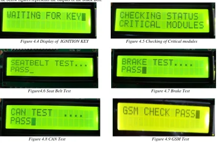
Ignition on Module:
When the IGNITION is ON it has to initialize the LCD. Then it displays the message Black Box For Vehicle Diagnosis. Later it waits for an IGNITION Key. This key represents the start of the vehicle. Then it checks for the critical parameters like BRAKE, SEAT BELT, CAN and GSM. When all these conditions are passed then only the DC Motor gets started otherwise it displays Failure message.
The below figures represents the outputs of the Black Box.
Figure 4.4 Display of IGNITION KEY Figure 4.5 Checking of Critical modules
Figure4.6 Seat Belt Test Figure 4.7 Brake Test
Figure 4.10 Display of Status Figure 4.11 DC Motor Status
If any of the condition fails then a message is shown on the LCD saying the status is failed and the DC motor is never turned ON until it is rectified. This condition prevents accidents while it checks for every critical parameter at the start of the vehicle.
Figure 4.12 Brake Failure condition Figure 4.13 Seat Belt Failure condition
Figure 4.14 Display of failure status
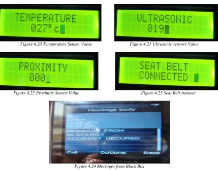
Whenever an accident is occurred it will stop the vehicle and displays a message ACCIDENT OCCURED. The GSM module present in the vehicle send a message to the owner saying the accident is occurred. At this point of time the sensors will calculate the parameters and stores them into the memory. These values are retrieved later in order to determine how the accident is occurred.
Figure 4.15 Display of Accident Occurrence Figure 4.16 Vehicle Condition
Figure 4.17 Display of Message Sent
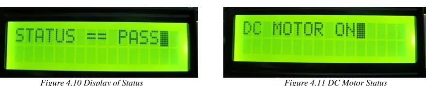
Retrieving data from EEPROM:
After the accident is occurred then every details of sensors is calculated and stored in the memory. These values are very useful to know how the accident is occurred. The values which are recovered are shown in the below figures.
Figure 4.20 Temperature Sensor Value Figure 4.21 Ultrasonic sensors Value
Figure 4.22 Proximity Sensor Value Figure 4.23 Seat Belt statuses
Figure 4.24 Messages from Black Box
The message is displayed in the phone after the accident is occurred to the vehicle. This is sent to the emergency numbers by the GSM module which is fixed in the vehicle.
VI.
FUTURE ENHANCEMENTS
Use of GPS module with this system will be helpful in finding the accident location and take quick rescue operations. We can enhance the present system to check other parameters like fuel level, tyre pressure and working of headlights before starting the vehicle .Many other critical parameters can be read and stored in the memory.
Another useful add-on to the present system could be cameras on front and backsides which keep recording live images and storing them in memory. This video data would be much useful for accident investigation.
ACKNOWLEDGMENT
This work is supported by Kuppam Engineering College and thanks for valuable references provided by the authors. Any opinions, findings, and conclusions or recommendations expressed in this material are those of the authors and do not necessarily reflect their views
I would also like to express my gratitude to all other members of the faculty of Electronics and Communication Engineering department for their cooperation.
I also express my gratitude to my parents for the support they have given me so far. I would like to thank my dear friends, for their kind-hearted cooperation and encouragement
REFERENCES
1.
G. Hayes, F. Blosser, "Motor Vehicle Crashes Claim More than a Million Accident Position Lives Worldwide", CDC Injury Center Media Relations, Press Release, At The Ajkident April, 2004.2.
http://www.airbagcrash.com (General Motor Event Data Recorders)3.
Thomas K. Kowalick, "Black Boxes: Event Data Recorders", MICAH,summer 2005.4.
K. Kowalick, "Black Boxes: Event Data Recorder Rulemaking for Automobiles", MICAH, summer 2006.5.
Thomas K. Kowalick, "Fatal Exit: The Automotive Black Box Debate", Wiley, IEEE Press, Feb. 2005.6.
Available [online]: www.alldatasheet.com7.
M. A. Mazidi, J. C. Mazidi, R. D. Mckinaly, the 8051 Microcontroller and Embedded Systems, Pearson Education, 2006.8.
http://www.keil.com9.
http://www.microcontroller.com/EmbeddedSystems.asp?c=11#1P. Ajay Kumar Reddy, obtained B.Tech degree from Kuppam Engineering College, Kuppam. He has completed M.Tech degree in the area of Embedded Systems under JNTU Anantapur. He is working as Assistant Professor in department of ECE, Kuppam Engineering College, Kuppam. His areas of interests are Embedded Systems, Microprocessors and Microcontrollers.
#2P. Dileep Kumar, obtained B.Tech degree from Kuppam Engineering College, Kuppam. He has completed M.Tech degree in the area of Embedded Systems under JNTU Anantapur. He is working as Assistant Professor in department of ECE, Kuppam Engineering College, Kuppam. His areas of interests are Embedded Systems, Electronic Devices and Circuits, Microprocessors and Microcontrollers.
#3K. Bhaskar Reddy, obtained B.Tech degree from SVPCET, Puttur. He has completed M.Tech degree in the area of Embedded Systems in Sastra University. He is working as Assistant Professor in department of ECE, Kuppam Engineering College, Kuppam. His areas of interests are Embedded Systems, Robotics, Microprocessors and Microcontrollers.
#4 E.Venkataramana, obtained B.Tech degree from RGMCET, Nandyal. He has completed M.Tech degree in the area of Electronics Design and Technology in NIT Calicut . He is working as Assistant Professor in department of ECE, Kuppam Engineering College, Kuppam. His areas of interests are Embedded Systems, VLSI Design, Signal Processing, Microprocessors and Microcontrollers.
#5M.Chandra Sekhar Reddy, obtained B.Tech degree from Kuppam Engineering College, Kuppam. He has completed M.Tech degree in the area of VLSI System Design under JNTU Anantapur. He is working as Assistant Professor in department of ECE, Kuppam Engineering College, Kuppam. His areas of interests are VLSI Design, Nano Technology, Microprocessors and Microcontrollers.