ISSN (e): 2250-3021, ISSN (p): 2278-8719 Vol. 04, Issue 03 (March. 2014), ||V5|| PP 07-11
Error Detection using Orthogonal Code
Ms.Mrunal S.Panse, Ms.Snehal Meshram, Ms.Darshana Chaware, Ms.A.Raut
Electronics Department, Rajiv Gandhi College of Engg. & Research,Nagpur R.T.M.University,Nagpur. India.
Abstract: -when data is transmitted through a channel(wired or wireless),some noises may affect the reliability of data. Because of this actual information get changed. This is reffered as error. Therefore error detection and correction techniques are required at the receiver. Orthogonal code is one of the coding technique which detect as well as correct the corrupted data. In this method each k-bit data set is converted into n-bit orthogonal code. An n-bit orthogonal code contains n/2 1‟s and n/2 0‟s,that means parity of this code is always zero. In this paper we present a new methodology to enhance the error correction capability of orthogonal code. This technique is implemented using VHDL and field programmable gate array(FPGA).
Keywords: -Orthogonal code, Antipodal code, Error detection and correction.
I. INTRODUCTION
Every communication system must be able to transfer data from one device to another with acceptable accuracy. Whenever data is transmitted from one point to another,one or more bits may change because of interference. In single bit error,a 0 is changed to 1 or 1 to a 0. In burst error, multiple bits are changed[5]. Some of the error detection techniques can only detect errors,such as cyclic redundancy check;other are designed to detect and correct errors, such as salomon codes[5].however the existing techniques are not able to achieve high efficiency and to meet bandwidth requirements, especially with the increase in the quantity of data transmitted. orthogonal code is one of the code that can detect errors and correct corrupted data[1].
II. ORTHOGONAL CODE
Orthogonal codes are binary valued and they have equal number of 1‟s and 0‟s. An n-bit orthogonal code has n/2 1‟s and n/2 0‟s.that means there are n/2 positions where 1‟s and 0‟s differ. Therefore all orthogonal codes will generate zero parity bits. The main reason for using orthogonal scheme is that they are not sensitive to the near-far effects and as cross correlation of each generated orthogonal code is zero, detection of corrupted code sequence is easy[1]. The concept is illustrated by means of an 8-bit orthogonal
code as shown in table-1. It contains 8-bit orthogonal codes and 8-bit antipodal codes. Antipodal codes are the inverse of orthogonal codes, they are also orthogonal among themselves as shown in table-1,each orthogonal and antipodal code generate zero parity bit. In orthogonal coding technique transmitter does not send any parity bit since the parity bit is known to be always zero.
TABLE-1
transmitter, k-bit data set is mapped into unique n-bit orthogonal code.where n=2^(k-1). For example,a 4-bit data set is represented by a unique 8-bit orthogonal code[d]. Orthogonality of each generated code is checked by finding the cross correlation with the previously generated codes.if the correlation is zero then only
Orthogonal code p Antipodal code p
0 0 0 0 0 0 0 0 0 1 1 1 1 1 1 1 1 0 0 1 0 1 0 1 0 1 0 1 0 1 0 1 0 1 0 0 0 0 1 1 0 0 1 1 0 1 1 0 0 1 1 0 0 0 0 1 1 0 0 1 1 0 0 1 0 0 1 1 0 0 1 0 0 0 0 0 1 1 1 1 0 1 1 1 1 0 0 0 0 0 0 1 0 1 1 0 1 0 0 1 0 1 0 0 1 0 1 0 0 0 1 1 1 1 0 0 0 1 1 0 0 0 0 1 1 0 0 1 1 0 1 0 0 1 0 1 0 0 1 0 1 1 0 0
code is accepted otherwise repeat request is generated. This correlation process is governed by following equation[4],where a pair of n-bit codes X1,X2....Xn and Y1,Y2...Yn are compared to produce,
𝑹 𝒙, 𝒚 = 𝑿𝒊 ∙ 𝒀𝒊
𝒏
𝒊=𝟏
<𝒏
𝟒− 𝟏 (1)
R(x,y) is correlation function. n/4 is the threshold value between two orthogonal codes. It is given by following equation
𝐝𝐭𝐡=
𝐧
𝟒 (𝟐)
Where n is the code length and dth is the threshold midway between two orthogonal codes[1]. For 8-bit orthogonal code we have dth=8/4=2.For reliable detection extra 1-bit offset is added to eq. (1).
𝒕 = 𝒏 − 𝑹 𝒙, 𝒚 =𝒏
𝟒− 𝟏 (3)
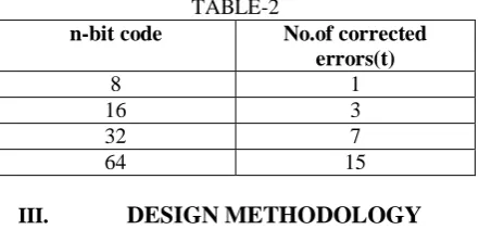
Where t is the number of errors that can be corrected by means of an n-bit orthogonal code. For example, a single error correcting orthogonal code can be constructed by means of an 8-bit orthogonal code (n = 8). Similarly, a three error correcting orthogonal code can be constructed by means of a16-bit orthogonal code (n = 16), and so on. Table-2 below shows a few orthogonal codes and the corresponding error correcting capabilities.
TABLE-2
n-bit code No.of corrected errors(t)
8 1
16 3
32 7
64 15
III. DESIGN METHODOLOGY
To generate orthogonal code ANDing and XORing operations are used. Evary k-bit data is compared with its 2𝑘 possible combinations using ANDing and then XORing of these results is performed.This gives the
unique n-bit orthogonal code for every k-bit data set. The function of transmitter and receiver is described below.
A. Transmitter
Transmitter contains encoder, orthogonality check and parallel to serial converter. Encoder encodes incoming k-bit data set into equivalent n-bit orthogonal code, where n=2𝑘−1. For example,4-bit data is encoded
into 8-bit(24−1
) orthogonal code. Every newly generated code is then compared with previously generated code for checking the orthogonality. If their auto correlation satisfy eq.(1) then it is a valid orthogonal code otherwise it will be rejected. This generated code is then transmitted serially with the help of parallel to serial converter.
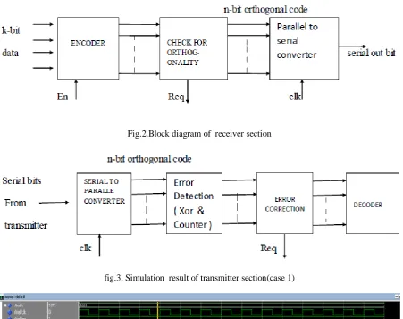
B. Receiver
The received serial bits are converted into n-bit parallel code by serial to parallel converter.The number of 1‟s in this parallel code are then count. If “count” is equal to n/2 then it is correct orthogonal code without error and if it is not equal to n/2 then it is considered as corrupted code. Number of corrupted bits are calculated by “count ± (n/2)”. In error correction block this n-bit parallel code is compared with all the codes in the lookup table. This is done by counting the number of ones in the signal resulting from „XOR‟ operation between the received code and each combination of the orthogonal codes in the lookup table. A counter is used to count the number of 1‟s after XOR operation. It also searches for the minimum count. The orthogonal code in the lookup table which is associated with the minimum count is the closest match for the corrupted received code. The matched orthogonal code in the lookup table is the corrected code,which is then decoded to k-bit data. associated with more than one combination of orthogonal code then a signal, REQ, goes high.
IV. IMPLEMENTATION
The simulation has been performed using ModelSim SE V6.2 software.
1. Transmitter
next input data is given to encoder,if EN signal is high,it is converted into equivalent orthogonal code. This newly generated code is labelled as “nwcode”. Now this nwcode is compared with previously generated txcode. If their autocorrelation satisfy eq.2 then nwcode is considered to be valid orthogonal code,otherwise “req” signal will goes high to indicate invalid orthogonal code. Hence request for regenerate is made.The RTL schematic for encoder is shown in fig.9.which indicates how the signals are processed internally.
2. Receiver
At receiver side,received serial bits are converted into n-bit parallel code by serial to parallel converter. Counter is used to count the number of 1‟s after XOR operation between received code and all the look up table entries. It also gives minimum count of 1‟s among them. The orthogonal code “ortho” associated with minimum count is the closest match for the received code,which is then decoded to final data. Three different cases result from this simulation. In the first case, the received code has a match in the lookup table.In the second case, the received code has no match in the lookup table.In this case the single bit error is detected and corrected by the receiver. In the third case, there is more than one possibility of closest match in the lookup table.The value of minimum count is associated with more than one orthogonal code and thus it is not possible to determine the closest match in the lookup table for the received code[1]. Then the signal labelled „REQ‟ goes high, which is a request for a retransmission.
V. CONCLUSION
The previously done research shows that for a k-bit data, the corresponding n-bit orthogonal code is able to detect orthogonal code in the lookup table. The numbers of these combinations are 2k. Hence the percentage of detection is given by (2^n-2^k)/2n %. Similarly, the system is able to correct up to (n/4)-1 bit error and the number of clock cycles required to process the received code are (2n+2). For example when a 4-bit data is encoded in to 8- bit orthogonal code; it has 24 = 16 combinations of orthogonal code. Therefore, out of 256 possible combinations of 8-bit received code the receiver will not able to detect error in those codes which are one of the combinations of orthogonal code. Hence the detection percentage for 8-bit orthogonal code is given by (28 - 24)/28 = 93.57% and also able to correct single bit error. Similarly, the percentage of detection for 16-bit orthogonal code is 99.95% and gives 3-bit of error correction[1]. Following table-3 shows the data detection capacity of orthogonal code.
TABLE 3 ORTHOGONAL CODES AND THE CORRESPONDING DETECTION RATES.
Fig.1. Block diagram of transmitter section
Fig.2.Block diagram of receiver section
fig.3. Simulation result of transmitter section(case 1)
Fig 4. Simulation result of transmitter (case2)
Fig.6 Result of receiver (case 1) :
Fig.7 Result of receiver (case 2) :
REFERENCES
[1] N. Kaabouch, A. Dhirde, and S. Faruque, “Improvement of the orthogonal Code Convolution capabilities using FPGA implementation”,IEEE Electro/Information
Technology Proceedings, pp. 380-384, 2007.
[2] A.Mitra, “On Pseudo-Random and Orthogonal Binary Spreading Sequences”, International Journal of Information and Communication Engineering ,pp.447-454, 2008
[3] Siwaruk Siwamogsatham and Michael P. Fitz, “Improved High- Rate Space-Time Codes via Orthogonality and Set Partitioning” , IEEE Proceeding,264-270, 2002.
[4] Luca Reggiani, Annalisa Tomasetta, Gian Mario Maggio, “Orthogonal Convolutional Modulation for UWB Impulse Radio Communications”, IEEE conference ISCAS . pp2441-2444, 2006
[5] S. Faruque, “Error Control Coding based on Orthogonal Codes”, Wireless Proceedings, Vol. 2, pp. 608-615, 2004.
[6] B.Forouzon, “Data Communication and Networking”,Tata McGraw-Hill publication,4th edition,2008 [7] Yao Wang, “Error Control And Concealment For Video Communication: A Review”, Proceedings Of
![table.The value of minimum count is associated with more than one orthogonal code and thus it is not possible to determine the closest match in the lookup table for the received code[1]](https://thumb-us.123doks.com/thumbv2/123dok_us/8354279.1668128/3.595.187.412.291.488/minimum-associated-orthogonal-possible-determine-closest-lookup-received.webp)