Design Of 11/0.415 kV Substation Using
Applicable International Codes
Oyeleye, M. O.
Department of Electrical and Electronics Engineering Federal University of Technology Akure,
Nigeria [email protected]
Abstract—This research focus on design of 11/0.415 kV distribution substation. The research was carried out to overcome the loss of power supply due to overloading of an existing 11/0.415 kV distribution substation in a community area, Ikorodu, Lagos State, Nigeria. Data were collected from concerned power utility company -peak load current, supply voltage, and frequency. Appropriate existing algorithm, tested and reliable codes on past commissioned of multinational projects were applied to the collected data to achieve the design of this project. Reliable, efficient, safety of the substation, safe operation of end users equipment and properties were put into consideration by carefully design associated protective devices on high tension and low tension sides using suitable and applicable international codes. Grounding of the substation and lightning arrester were properly designed and sized for safety of the personnel, equipment and effective discharge of lightning over voltages to the ground using appropriate codes. Design of 11/0.415 kV substation that meet load demand of 60% loading and 75% of previous loading including 1.25 future expansion factor overloading of the transformer was achieved. Previous loading of 75% which will cater for 2hrs overloading is designed thus long operational life of the transformer. The common tripping of high voltage (HV) fuse when a transformer is overloaded is avoided in HV side. The protection of the transformer and all other elements were highly considered in this work. The life span of the substation transformer increases in this type of design. This research recommends that for high reliability and efficiency of 11/0.415 kV substation, transformer should be loading at 60% loading and 75% previous loading for 2hrs overloading, 1.25 future expansion factor should be considered, transformer should not be design to operate at 100% previous loading and derating factor should be considered in sizing cable when more than one in parallel.
Keywords—substation; code; grounding; overloading; transformer.
1. Introduction
Substations play key role in reliability of any electric power systems. At distribution level, it is use in dividing
resulted into undesirable load shedding 10years ago. As a result of this, another substation was commissioned about 7years ago. Presently, the area is experiencing same problem of load shedding. The occupants of this substation are high caliber people which include a vice chancellor of a private university in Nigeria, a retired pharmacist of Federal University Teaching Hospital in Nigeria, a Managing Director and medical practitioner in Lagos State, a practicing consulting engineer and lecturer in a Nigeria Federal University, directors in the Lagos States coupled with the high concentration of the people where street lights are highly needed to reduce mischievous characters in the night. Loading of transformer at 60% to cater for future expansion is a necessity. Code recommends 25% future expansion of the load. It therefore means that 25% of the 60% loading yields 75% previous loading. This will allows moderate overloading at 75% previous loading. The design in work is based on this philosophy. This will facilitates long life of the transformers or otherwise the substation. Apart from load shielding that motivated this work which was mentioned earlier, another motivation is inability of the author to design a 33/0.415 kV substation after 2years of obtaining his Master Degree when working with an international consulting firm. This bottleneck should be overcome with our first and second degree holders, thus the high motivation of this research.
1.1 Overview of power system
Power demand is increasing rapidly due to increase in industrial, commercial and agricultural consumers. It is required to have large blocks of power generation in country like Nigeria where transmission and distribution losses are very high (Onohaebi and Kuale, 2007). In order to meet consumer demand, more generating stations (GS) like Thermal, Gas, Hydro and Nuclear are needed which are far away from consumer. To transmit large amount of power up to long distance, extra high voltage lines are necessary for transmission to the load centers for increased reliability of supply, greater system stability and hence cheaper electric energy (Gupta, 2005, Nawaz, 2016). In between power stations and consumers, transformation and switching stations called substations are necessary for the control of electrical power system. This research focus on the design of 11/0.415 kV distribution sub-station (11/0.415 kV) is review in this work.
1.2 Substations
Electric power is produced at the power generating stations which are generally located far away from the load centers. High voltage (HV) transmission lines are used to transmit the electric power from the generating stations to the load centers. Between the power generating station and consumers a number of transformations and switching stations are required. These are generally known as substations. Substations are important part of power system and form a link between generating stations, transmission systems and distribution systems. It is an assembly of electrical components such as bus-bars, switchgear apparatus, power transformers, low voltage panels, protective device and the likes.
Their main functions are to receive power transmitted at high voltage from the generating stations and reduce the voltage to a value suitable for distribution. Some substations provide facilities for switching operations of transmission lines, others are converting stations. Substations are provided with safety devices to disconnect equipment or circuit at the time of faults. Substations are the convenient place for installing synchronous condensers for the purpose of improving power factor and provide facilities for making measurements to monitor the operation of the various parts of the power system (Gupta, 2010, Johnson, 2015, Nawaz, 2016)
The substations may be classified according to service requirements and constructional features (Nawaz, 2016). According to service requirements it is classified in to transformer substations, switching substations and converting substations (Nawaz, 2016).
1.2.1 Transformer substations
Majority of the substations in the power system are classified under this type. They are used to transform power from one voltage level to another voltage level. Transformer is the main component in such substations. Transformer substations are further classified into Step-up substations, Primary grid substations, Secondary substations and Distribution substations (Johnson, 2015).
1.2.1.1 Step-up substations: These substations are usually located at the generating stations.
Generating voltage of the order of 11kV needs to be stepped up to a primary transmission voltage level of the order of 330 kV or 400 kV depending on the country.
1.2.1.2 Primary grid substations: These substations are located at the end of primary transmission lines and the primary voltage is stepped down to suitable secondary voltages of the order of 132 kV or 33 kV.
1.2.1.3 Secondary substations: The voltage is further stepped down to 11kV. Large consumers are supplied power at 11 kV (Gupta, 2005, Johnson, 2015).
1.2.1.4 Distribution substations: These substations are located near the consumer localities to supply power at 415V, three phase or 240V, single phase to the consumers.
1.2.2 Switching substations
These substations are meant for switching operations of power lines without transforming the voltage. Different connections are made between the various transmission lines.
1.2.3 Converting substation: Such substations are meant for either converting AC to DC or vice versa. Some are used to change the frequency from higher to lower or vice versa for industry utilizations.
1.2.4 Substation according to constructional features substations
1.2.4.2 Outdoor substations: All equipment such as transformers, circuit breakers, isolators, etc., is installed outdoors.
1.2.4.3 Underground substations: In thickly populated areas where the space is the major constraint, and cost of land is higher, under such situation the substations are laid underground.
1.2.4.4 Pole mounted substations: This is an outdoor substation with equipment installed overhead on a H pole or 4 pole structure.
1.3 Substation Elements
Substation equipment are required to control and maintain power supply (Johnson, 2015). Substation equipment design is very important from the point of view of reliability of system supply. In this project, main objective is to size 11/0.415 kV substation element which has higher reliability and security from design point of view. The meaning and purpose of substation element are discussed underneath
1.3.1 High Voltage Fuse
The word fuse is a short form of “fusible link” and it is also protection device capable of protecting a circuit from overload currents and short circuit currents. Fuses are rated in terms of many aspects. These include voltage, current and the type of application. A high rupturing capacity (HRC) fuse is a fuse that has a high breaking capacity (higher kA rating. A general approach is that it should operate at 1.25 times the rated current. A typical fuse is made of silver-coated copper strips and granular quartz (Gupta, 2010, Nawaz, 2016).
1.3.2 Lightning Arrester (LA)
The substation elements such as conductors, transformers, etc., are always erected outdoor. Whenever light surges occur a high-voltage pass through these electrical components causing damage to them, either temporary or permanent damage depending on the magnitude of voltage surge (Melodi and Oyeleye, 2017). Therefore, to avoid this difficulty, lightening arresters are placed to pass the entire lightening surges to earth. There are many arresters which are used to ground the switching surges, however metal oxide lighting arresters is used in this research base on superior energy absorption capability, better surge protection, more stable protective characteristics and substantial reduction, overvoltage across equipment as compared to other types of arrester. (Gupta, 2010, Weedy, et., al 2012, Nawaz, 2016,) A general approach is that it should operate at 1.1 times the rated voltage (NEC, 2005). The down conductor for discharging current to the ground is sized to 161mm2 (Oyeleye, 2017).
1.3.3 Transformer
A static electrical machine used for transforming power from one circuit to another through electromagnetic induction circuit without changing frequency is termed as power transformer (Dasgupta, 2007, Gupta, 2010, Nawaz, 2016). The transformers are generally used to step down or
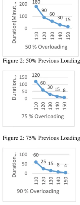
step up the voltage levels of a system for transmission and generation purpose. These transformers are classified into different types based on their design, utilization purpose, installation methods, and so on. (Nawaz, 2016). The continuous loading of transformer for high efficiency is 50% (NEMA Standard, 2002, Bureau of energy efficiency, 2005, NAEEEP, 2011, Zenatix, 2015). A variation of 50-60% (Bureau of Energy Efficiency, 2005) and can be considered for a transformer which has not been repaired (Zenatix, 2015). If the transformer is loaded from 60% - 100% the loss varies between 0.4% - 1.9% percent (Schneider, 2015). However the overloading of a transformers depends on the transformer’s previous load or the corresponding oil temperature at the beginning of the overloading (Schneider, 2015). The permissible duration and percentage overloading is present in Figure 1 – 3 based on previous loading of 50, 75 and 90 percent respectively (Schneider, 2015).
Figure 2: 50% Previous Loading
Figure 2: 75% Previous Loading
Figure 3: 90% Previous Loading
1.3.4 Conductor and Cable
The material that obeys the electrical property conductance (mostly made of metals such as aluminum and copper) and that allows the flow of electric charge is called conductor. Conductor permits free movement of the flow of electrons through them. These are used for the transmission of electrical energy from one place (generating station) to another place (consumer point) through substations. Conductors are of different types and mostly aluminum conductors are preferred in practical power systems
180 90
60 30 15
0 100 200
110 120 130 140 150
Du
rati
on(
Minut
…
50 % Overloading
120 60
30 15 8
0 50 100 150
110 120 130 140 150
Du
rati
on
…
75 % Overloading
60
25 15 8 4
0 50 100
110 120 130 140 150
Du
rati
on
…
because its cheap and light in weight. Even though electrical conductivity of Aluminum (Al) is lesser than that of copper Cu (60%) for the same resistance for a given length, Al is still frequently prefer to Cu for bare electric conduction over long distance (Lakervi and Holmes, 1989, Gupta, 2005, Nawaz, 2016). Conductors are selected base on rating of loads and ambient conditions (moisture, temperature, exposure to sun and area to be installed). the ampacity of electrical components for the circuits are determined by current ratings and associated voltage drop as contained in Catalogues (ABB, 2005, Kable Metal , 2005, Nigerchin , 2006). Conductor can be for HV or LV distribution. Cable is a conductor covered with insulator (Hilsdorf and Matinez, 2015). Even though electrical conductivity of Al is lesser than Cu (60%) for the same resistance for a given length, Al is still frequently prefer to Cu for bare electric conduction over long distance in power distribution.
1.3.5 Insulation, Armoured Cable and Underground Cable
The insulation of cable started in late 1880 and the then insulation suffered deterioration of insulation called local electrical discharge. This problem was overcome in 1926 with oil-filled cable designed by Emanuelli. In 1950, increase in copper cost coupled with heavy weight switched attention in cable selection to aluminum for underground installation. Polyvinyl chloride (PVC) came to lime light in 1950 but limited in use by plastic flow at high temperatures and thus creates poisonous acidic gases. This short coming limit its use to low voltage. Underground cables insulating materials and Armoured Cable (AC) or cross linked Cable (XLPE) are used in underground work in order to protect the conductor from mechanical damage. Water and corrosion are also protected in AC and XLPE cables. Polyethylene (PE) is used in medium voltage while XlPE is preferred to PE due to its better heat capability under shortcircuit fault condition and higher temperature for normal operation (Lakervi and Holman, 1989).
1.3.6Low Tension Panel (LTP)
Feeder pillar is a cabinet for electrical equipment mounted immediately after low voltage side of a transformer in a substation in the street and controlling the electrical supply to a number of in a neighborhood. Feeder pillar can be described as an electrical enclosure used to provide electrical services for low voltage electrical applications. It is designed as a compact and robust for vandalism protection
1.3.7 Current Transformer (CT)
It is used for the measurement of the alternating current by taking samples of the higher currents of the system. These reduced samples are in accurate proportions with the actual high currents of the system. These are used for installation and maintenance of the current relays in substations for protection purpose which are normally has low-current ratings for their operation (Nagrath and Kothari, 2003, Nawaz, 2016). HV CT is used in this work.
1.3. 8 Voltage Transformer (VT)
It is quite similar to the current transformer, but it is used for taking samples of high voltages of a system for providing low-voltage to the relays of protection system and also to the low-rating meter for voltage measurement. From this low-voltage measurement, the actual system’s high voltage can be calculated without measuring high voltages directly to avoid the cost of the measurement system (Nagrath and Kothari, 2003, Nawaz, 2016). This is installed in low voltage panel.
1.3.9 Bus-Bar (LTP)
The conductor carrying current and having multiple numbers of incoming and outgoing line connections can be called as bus bar, which is commonly used in the low voltage panel. These are classified into different types like single bus, double bus and ring bus (Siemens, 2006, Nawaz, 2016).
1.3. 10 Line Isolator (HV)
In Power systems an isolator is a switch which is used to completely open a circuit which has been rendered dead by means of opening a circuit breaker for maintenance of equipment. It can be visually seen that an isolator is open and hence service man are assured that it is safe to work on the isolated equipment. The equipment to be worked on is further earthed mostly on either side so that electrical energy that could be in the equipment is completely discharged to earth further enhancing safety of the service man. An isolator is also used for sectionalizing power lines during fault location. Isolators are always opened in no load condition (after opening of circuit breakers) because it lags the mechanism of operating in high voltage (Nawaz, 2016, Gupta, 2005)
1.3.11 Grounding System
Grounding is the connection of part of an electrical circuit, accessible conductive parts of electrical equipment (exposed conductive parts) or conductive parts in the vicinity of an electrical installation (extraneous conductive parts) are connected to earth (Gupta, 2010, Nawaz, 2016)
Earth electrode is a metal conductor, a system of interconnected metal conductors or other metal parts acting in the same manner embedded in the ground and electrically connected to it, or embedded in the concrete which is in contact with the earth over a large area (e.g. foundation of a building). The earthing system in comprises of three main components which are ground conductor, connection between the ground conductor and ground electrode and Ground electrode.
1.4 Design Code
The design code of substation element are summarized in Table 1. The codes have been used on various projects successfully.. These projects include Olokola Liquefied Natural Gas (OKLNG), Ondo State, international petroleum companies and other substation projects.
2005; British International Standard, 1998, and Oyeleye, 2017)
S/N SUBSTATION
ELEMENT
CODE(MULTIPLYING FACTOR)/ STANDARD
1 Low Voltage fuse(secondary)
1.25
2 High Voltage fuse(primary)
1.25 (3.0, maximum)
3 Isolator 1.25
4 Cable/conductor 1.25 of rated value appropriate derating factor 5 Circuit breaker /
Panel/Busbar
1.25
6 Load future expansion
1.25 of the actual load
7 Lighting Arrester
1.1
8 Ground
conductor, 𝐺𝑐 𝐺𝑐=
1
2∗ 𝑃ℎ𝑎𝑠𝑒 𝑐𝑢𝑟𝑟𝑒𝑡, 𝐼𝑝
9 Lightning down conductor and rod/mat
161mm2
10 Grounding resistance
10Ω max (IEC and BS)
2. METHODOLOGY 2.1 Load Data
Existing load was obtained from PHCN record in order to determine and size an appropriate transformer including the substation elements that will cope the new extension of a community area, Lagos State.
2.2 Design Considerations
Design considerations are employed for safety and operation of designed of a substation. The substation design consideration include:
i. availability of an existing high voltage supply (11 kV)
ii. incorporation of future expansion of load (1.25 factor)
iii. reliability of elements used(reliable element from trusted vendor)
iv. effective grounding (code Compliance)
v. ability of protective element to trip when desire (code compliance).
vi. 60% loading of Transformer
vii. 75% previous loading to cater for 2hours overloading.
2.3 Sizing of Substation Elements
Applicable and appropriate codes, guidelines and algorithm were used to size the substation elements, Table 1 in addition to the anticipated load of the substation.
2.3.1 Transformer Sizing
Sizing of transformer is based on Equation 1 Equation (1) is used.
𝑃 = ∛ 𝐼 𝑝𝑟𝑖𝑉𝑝𝑟𝑖 (1)
Where Ipri is the primary current and Vpri is the primary
voltage.
2.3.2 High Voltage (HV) Fuse 𝑃 = ∛ 𝐼 𝑝𝑟𝑖 𝑉𝑝𝑟𝑖 (2)
Where P is the three phase power in Volt Ampere (VA). From equation (2), we obtain equation (3). Equation (3) is used to determine HV fuse.
𝐼𝑟𝑎𝑡𝑒𝑑 =𝑃/ ∛ 𝑉𝑟𝑎𝑡𝑒𝑑 A (3)
Where 𝐼𝑟𝑎𝑡𝑒𝑑 is the primary current that the low voltage circuit will carry without damaging the primary conductor.
2.3.3 0.415 kV Low Voltage Panel (LVP) Sizing
LVP sizing is based on equation (4).
𝐿𝑉𝑆𝑃 = 1.25 ∗ 𝐼𝑟𝑎𝑡𝑒𝑑(𝑠𝑒𝑐) A (4)
Where 1.25 is the multiplying factor for panel.
2.3.4 Isolator
According to Table 1, design of HV fuse correspond to isolator sizing since isolator are connected in series with the HV fuse. The same equation (2) is used.
2.3.5 Lightning Arrester (LA) Selection
The determination of LA was done using equation (5)
LA size =10% ∗ 𝑉𝑚𝑝𝐻𝑉 (5)
Where 𝑉𝑚𝑝𝐻𝑉 is the maximum permissible high voltage.
2.3.6 Low Voltage Circuit Breaker (LVCB)
Required load should be sized to 60% of the transformer in order to cope with the expected load and 75% previous loading of a transformer. 75% loading is essential for 2hours overloading. LVCB is sized using equation (6).
𝐼sec 𝐹.𝐸 = 1.25∗𝐼𝑠𝑒𝑐 (6)
Where Isec is the secondary current (load current); Isec F.E is
the secondary current taking future expansion into consideration; 1.25 it the future expansion multiplier
Where Irated is the current carrying capacity of the
secondaryside of transformer.
2.3.7 H.V Cable
Equation (7) is used to determine H.V cable size, H.V cable rated.
𝐻. 𝑉 𝑐𝑎𝑏𝑙𝑒𝑟𝑎𝑡𝑒𝑑 =1.25 ∗ 𝐼pri 𝑟𝑎𝑡𝑒𝑑 A (7)
Where 1.25 is the cable multiplying factor and Ipri rated is the
primary rated current.
2.3.8 LV Cable
𝐶𝑎𝑏𝑙𝑒𝑆𝑒𝑐= 1.25 ∗ 𝐼𝑠𝑒𝑐 𝑟𝑎𝑡𝑒𝑑 A (8)
Where 1.25 is cable multiplying factor and Isec rated is the
secondary rated current.
2.3.9 Grounding System
Grounding conductor, Gc, is determined using equation (9).
𝐺𝑐=12∗ 𝐼𝑝 (9)
Grounding system resistance value should conform to international standard of BS(1992); and IEC(2006); and Oyeleye & Makanju (2017) of 10Ω maximum.
2.10 Down conductor
Down conductor is sized in accordance to Table 1.
3. RESULTS and DISCUSSIONS
3.1 Results
The results of design of 11/0.415kV using Table 1 and applicable equation 1 to 9 are presented in Table 2.
Table 2: Parameters of 11/0.415 kV Designed Substation
SUBSTATION ELEMENTS
DESIGNED VALUES
RECOMMENDED 1.25 MULTIPLYING FACTOR CONSIDERATON
CABLE SIZING
60% 25%
FE
Transformer sizing 500 kVA 0.6 0.75
High Voltage Fuse 26.2A 15.7
A 16A 25A
Low Voltage panel sizing 696A 800A
Isolator 26A 200A
Lightning arrester 12.1 kV
Low voltage CB 696A 417.4
A 522A 600A
HV cable 26.2A 33A 22 mm2 (Al)
LV cable 696A 870A 4nos of 2 x 400mm
2
(S-C, Cu)
Earthing conductor 348A 150mm2
Down conductor 161mm2 180mm2
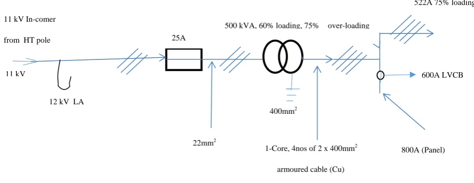
From Table 2, Figure 1 is obtained.
Figure 1: Single Line Diagram of 11/0.415 kV Designed and Recommended Substation Elements
3.2 ANALYSIS
From Table 1, the sizing of the substation elements conform to the designed codes used in this research. The transformer is designed to operate at 60% loading. 25% future expansion was considered. This future expansion consideration, pave way for the transformer to operate at
75% previous loading for 2 hours overloading. The HV fuse is 16A and 25A recommended since 16A designed value is not available. The 25A recommended HV fuse is still lower that the available 26A designed value. This means that the usual frequent blowing of the HV fuse is
11 kV In-comer
from HT pole 25A
1-Core, 4nos of 2 x 400mm2
armoured cable (Cu)
522A 75% loading
800A (Panel)
12 kV LA
22mm2
400mm2
522A
600A LVCB
500 kVA, 60% loading, 75% over-loading
overcome in this design method thus reduce difficulty in maintenance.
The substation elements are sized based on the renowned international codes, Table 1. This means that the designed substation will be reliable, safe, and efficient and meet the design philosophy. However in sizing the HV and LV cables, single core cable was considered suitable for the load putting derating factor of 0.8 in to consideration since two cables are touching from Nigerchin cable catalogue. The derating factor is necessary to avoid overheating of the cable.
The recommended lightning arrester is adequate to discharge surge current into the ground due to the designed lightning and earthing systems that conform to the existing literatures. This design will allow 11/0.415 kV substation to operate safely, effectively and efficiently thus increase station reliability and efficiency. It is good to know that where the designed element is not readily available, the next available element rating is recommended.
4. CONCLUSIONS AND RECOMMENDATIONS 4.1 Conclusions
i. Design of 11/0.415 kV substation at 60% load requirement is achieved.
ii. 75% previous loading of the transformer including future expansion was achieved.
iii. Previous loading of 75% which will cater for 2hrs overloading is achieved thus long operational life of the transformer and cheapness in overall maintenance cost.
iv. The common tripping of HV fuse when a transformer is overloaded is avoided in HV side in this work.
v. The protection of the transformer and all other elements are achieved.
vi. The lightning arresting system is adequate to discharge surge current safely into the ground.
4.2 Recommendations
In order to achieve high operational performance of 11/0.415 kV substation, the followings are recommended:
i. transformer should be design to operate at 60% loading without future expansion consideration, ii. adequate substation future expansion should be
put into consideration,
iii. transforms should not be designed to operate at 100% loading (previous loading), and
iv. derating factor should be considered to avoid cable overheating.
v.this work can be applied to substation design.
REFERENCES
(1) D.O. Johnson. Reliability Evaluation of 11/0.415kv Substations A Case Study of Substations in Ede Town. International Journal of Engineering Research & Technology (IJERT) ISSN: 2278-0181 Vol. 4 Issue 09, September-2015.
(2) H.A Boknam, S. Park, C.Shin, S. Kwon, and S. Park, “Power Quality Monitoring on Distribution
Network using Distribution Automation System’’, 19th International Conference on Electricity Distribution Vienna, Paper 0426, 2007.
(3) Warwich Manufacturing. “Introduction to Reliability Engineering.” University of Warwich 2007.
(4) US Department of Energy, “Electricity Delivery and Energy Reliability.” Smart Grid Investment Programme 2012 www.smartgrid.gov accessed on 4 March 2015
(5) Electric Power Research Institute’s White Paper (EPRI)“Reliability of Electric Utility Distribution Systems”, Palo Alto, CA: 1000424. 2000
(6) O. S. Onohaebi and P. A. Kuale. Estimation of technical losses in the Nigerian 330 kV transmission Network. International Journal of Electrical and power Engineering 1(4), 2007 pp 402-409.
(7) J. B. Gupta. A course in Electrical Installation Estimating and Costing 8th edition. Publisher S.K Kataria and Sons, 6, Guru Nanak Market Nai sarak Delhi 110006. 2005 pg. 497.
(8) M. S. Nawaz. Design and Construction of 33/11 KV Line & Substation. International Research Journal of Engineering and Technology (IRJET) Volume 03 Issue: 07 2016, pp. 2395 -0056 (9) J.B. Gupta. A Course in power systems publisher
S. K. Kataria and sons 4760-61/23, Anasari road darya gnj, New Delhi 433 of 691 2010.
(10)A. O. Melodi and M. O. Oyeleye. Modeling of lightning strike events, and it’s correlational with power outages in south-west coast, Nigeria. International journal of Electrical and computer Engineering Vol 7. 2017, pp. 3262-3270.
(11)B.M. Weedy, B. J. Cory, .N Jokus, J. B. Ekanayake and G. Strabac. Electric power systems 5th Edition. Publisher John wiley and Sons Ltd, the Atrium gate, chichester Sussex Po198SQ, united kingdom, 2012.
(12)National electrical code, NEC. International series, 2005, pp. 711.
(13)M.O. Oyeleye. Evaluation and planning of lightining protection efficacy on Nigerian high voltage installations.Ikorodu 11 kV-132 kV system as case study. Phd thesis Federal university of Technology Akure, Nigeria 2017, pp.122-125.
(14)I. Dasgupta. Design of transformer, publisher McGraw-Hill company limited New Delhi, 2005, pp1.
(15)NEMA Standards Publication TP 1-2002, Technical report, Guide for determining energy efficiency for distribution transformers. 2002. (16)Bureau of Energy Efficiency (India).
Determination analysis of standards and labeling program for distribution transformers, 2003. (17)National Appliance and Equipment Energy
(18)Zenatix. Transformer Efficiency effect of loading.Zenatix.com/transformer-efficiecny-effect. 2015, pp. 7.
(19)Schenider electric . Low voltage and
medium Voltage Products catalogue. 2015, pp. 28 (20)E.Lakeri and E.J Holmes. IEE power engineering
series 9, 1989, pg116-118 pp. 319.
(21)ABB, XPLE cable system users guide, 1989, pp.31.
(22)Kable Metal catalog, Kable metal co., Ikeja lagos 2005, pp. 47.
(23) Nigerchin and wire,. Nigeria Wire and Cable catalog, Nigerchin and wire co., lagos 2006, pp. 47
(24) E. Hilsdorf, and M. Matinez . Porcelain insulators and covered conductors. A problemofdielectriccompatibility.Researchgate.n et/publication/283085314, 2015.
(25)I. J. Nagrath and D.P. Kothari,. Power system Engineering publisher Tata Mcgraw-Hill Publishing company limited New Delhi, 2003, pp. 653-654
(26)Siemens.Electrical Engineering Handbook Publisher New Age international Limited, New Delhi, 2006, pp. 749.
(27)British standard. Code of practice for protection of structures against lightning, 1992, pg112.
(28)IEC. Protection of structures against lightining- part 1: General principle IEC, 2006, 61024-1 Ed.1.0b.