Research Article
SysGRID: IEC 61850 and IEC 61499 Standard Based
Engineering Tool for Smart Grid Automation Design
Chen-Wei Yang
1,*, Gulnara Zhabelova
1,*and Valeriy Vyatkin
1,2,*1Department of Computer Science, Electrical and Space Engineering, Lulea University of Technology, Lulea, Sweden 2Department of Automation and Systems Technology, Aalto University, Helsinki, Finland
Abstract
The so called Smart Grid is said to be distributed in nature with an accompanying control architecture which is made up of a heterogeneous network of controllers communicating in a peer-to-peer manner. The paper proposes a novel computer-aided model-based system engineering process for the design of a Smart Grid applications from the initial design specification through to the validation of the control system and hardware deployment. The process is supported by the SysGRID tool, which plays the roles of a system configurator and device configurator adopted from the International Standard IEC 61850. SysGRID supports system-level design of automation logic in the form of function block networks compliant with the international standard IEC 61499. The capabilities of SysGRID are demonstrated through the process of designing a distributed protection application based on IEC 61850 and the resultant validation process in a close-loop co-simulation.
Keywords: IEC 61850, IEC 61499, SysGRID, SCL, Model-Based System Engineering, Sympathetic Tripping Received on 6 August 2014, accepted on 22 September 2014, published on 02 December 2014
Copyright © 2014 Chen-Wei Yang et al., licensed to ICST. This is an open access article distributed under the terms of the Creative Commons Attribution licence (http://creativecommons.org/licenses/by/3.0/), which permits unlimited use, distribution and reproduction in any medium so long as the original work is properly cited.
doi: 10.4108/ew.1.2.e5
*
Chen-Wei Yang, [email protected] Gulnara Zhabelova, [email protected] Valeriy Vyatkin, [email protected]
1. Introduction
The Smart Grid in the broad sense is understood to be the future power generation, transmission, distribution and consumption infrastructure enabled by advanced information, communication and control technologies. The Smart Grid evolves into a large, complex and interconnected system of systems, incorporating such components as distributed generation, energy storage systems, smart loads, new generation, solid state transformers and fault isolation devices evolving from a traditional centralized architecture to one which is more distributed [1].
The Smart Grid is expected to evolve to a level where traditional engineering techniques will be challenged by the complexity of the system requirements. This paper proposes a Model-Based System Engineering (MBSE) methodology which combines two industrial standards, IEC 61850 and IEC 61499 [2], for designing and testing of Smart Grid applications. The proposed design methodology encourages formal and consistent specification and design flow according to IEC 61850 [3],
design of distributed systems with IEC 61499 [4] and validation and testing of the application via co-simulation of the developed solution with a utility simulation model. The synergy between the two industrial standards IEC 61850 and IEC 61499 is discussed at [5] and a prototype case study of such a solution is demonstrated at [6], showing the applicability and the benefits of the solution for designing future distributed smart grid automation control systems.
The SysGRID tool was developed as part of this research work to support the design of substation automation control systems based on the MBSE design methodologies.
The paper is structured as follows. Chapter 2 outlines the state of the art and the motivation for this work. Chapter 3 will introduce the design process of SysGRID based on the MBSE methodologies. The architecture and main features of the tool are presented in chapter 4. The capabilities of SysGRID as a design environment will be illustrated using the example of a distributed protection application in chapter 5. Chapter 6 will conclude the paper with summary and outlook.
on Energy Web
2. State of the Art
According to the Smart Grid Reference Model [7] (SGAM) developed by the CEN-CENELEC-ETSI Smart Grid Coordination group for the European market, there are multiple interoperability layers within the proposed SGAM smart grid architecture. These interoperability layers include the business layer, the function layer, the information layer, the communication layer and the component layer. Since the development of the smart grid concept is still in its early stages, there is no standardized methodologies of how these interoperability layers could be tied together and interact with each other. Currently, there are existing industrial standards which are capable of tackling the challenges presented at each individual layers of the SGAM architecture and there are also existing research works which attempts to bridge these layers and this work is one such attempt to bridge the communication layer and the component layer.
One examples of existing works which attempts to harmonize the information layer and the communication layer is the work in [8] which attempts to bring semantic information to the IEC 61850 logical node information models with the industrial standards IEC 61968 and IEC 61970, two standards which are part of the Common Information Model (CIM) collection using ontology. IEC 61850 is a communication standard, which aims to standardize the exchange of information between interoperable devices. However, the information models, otherwise known as logical nodes are largely functional models, thus providing very little semantic relations between the logical node models. The CIM model on the other hand offers a higher level of abstraction compared to the IEC 61850 standards and thus can provide the lacking semantic relations between logical nodes.
The two layers, which this work attempts to address, are the communication layer and the component layer. As mentioned previously, IEC 61850 is largely a communication standard and thus, does not provide any semantic relations between the logical nodes. But most importantly from the automation perspective, IEC 61850 does not provide a standardized way of designing logical intelligences within each of the logical node models. Both works in [5, 6] have explored bridging the communication layer and the component layer with the industrial standards IEC 61850 and IEC 61499 respectively.
The two standards synergizes extremely well, especially when it comes to the design methodology of distributed based systems with IEC 61850 looking from the perspective of communication and substation design and IEC 61499 tackling the distributed automation control side. There are already existing works in [9-12] which exhibits positive results showing the viability of such solutions. This work attempts to take the next step by bring a unified systems engineering approach to design IEC 61850 and IEC 61499 based systems adopting
3. Power System Automation Design
Process Based on IEC 61850 and MBSE
3.1. SysGRID and MBSE
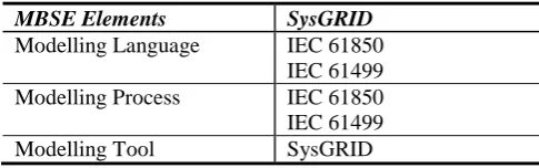
According to [13] there are three elements in a MBSE environment: The modelling language, the modelling tool and the modelling process. The tool SysGRID was developed as part of this research work, which utilizes the design methodologies of MBSE to design substation automation control systems. Table 1 presents these three core elements of MBSE engineering and the corresponding components in the SysGRID design tool. The modelling languages used are IEC 61850 and IEC 61499 and thus, the artefacts of IEC 61850 (Logical Nodes) and IEC 61499 (Function Blocks) are used to design the control system. The modelling process as based on the system design methodologies of IEC 61850 and IEC 61499, which specializes in design of distributed based systems in their respective domains. The final component is the Modelling tool, which ties the modelling language and the modelling process together is the SysGRID tool.
Table 1. Elements of SysGRID in MBSE
MBSE Elements SysGRID
Modelling Language IEC 61850 IEC 61499 Modelling Process IEC 61850 IEC 61499 Modelling Tool SysGRID
The benefits of SysGRID includes reduction in engineering costs, better validated Smart Grid applications and ability to see the impact of intelligent automation on electricity network performance. Firstly, a key feature of SysGRID is the ability to automatically generate control and automation software from the Single Line Diagram (SLD). SysGRID promotes "re-usable engineering", following the IEC 61850 and IEC 61499 standards. Secondly, SysGRID provides an automation and control logic editor, where distributed automation, control and protection algorithms can be designed. Thirdly, SysGRID uniquely offers the capability of co-simulation, which enables the validation of the entire system under design including the substation and distribution or transmission network. SysGRID simplifies the design of systems by supporting hardware abstraction at the design stage.
SysGRID: IEC 61850 and IEC 61499 Standard Based Engineering Tool for Smart Grid Automation Design
Description (SCD) file. Both SCD and SSD files are part of IEC 61850 Substation Configuration Language (SCL) which is used to configure different part of the substation automation system as specified in [3] in a formal XML format.
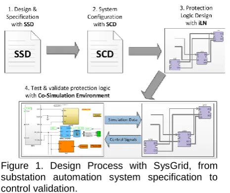
The adopted IEC 61850 design process with SysGRID is depicted on Figure 1. There are 4 main design steps in the SysGRID design tool chain. The design steps are:
1. Design and Specification with SSD 2. System Configuration with SCD 3. Protection logic design with iLN
4. Test and validation of protection logic with Co-Simulation
3.2. Design and Specification with SSD
The first step of the design process is to design the Single Line Diagram and capture the functional requirements. In IEC 61850, the customer functional specifications are formally captured in the SSD file. IEC 61850 offers the concept of Logical Nodes (LNs) as formal definitions of both the equipment requirements and the functional requirements [14]. All functions at this stage are abstracted from any implementation to allow optimisation [14]. At this level of design, the system is designed from an application point of and thus, the requirements as logical nodes are not allocated to devices. The resultant configuration at this stage is the SSD configuration file.
3.3. System Configuration with SCD
The second step of the design process is the engineering at the system level and the resultant configuration at this stage is the SCD configuration file. The resultant SCD file contains the complete configuration of the entire system, which includes the individual IED configuration and the communication subnetworks within the system. The SCD file is made up of five main sections. The five sections are the header, the substation, the IEDs, communication and the DataTypeTemplate sections [3]. The IED section contains the access points, servers, communication control blocks and the LNs for each IED devices. LN types used in the design are defined in the DataTypeTemplates section, which represents a signal list.
3.4. Protection logic design with iLN
The third step is to generate the control and the automation logic corresponding to the desired logical node functions as shown in step 3 of Figure 1.
SysGRID can automatically generate an executable IEC 61499 function block control system from the SSD file as shown in Figure 2Figure 2, in which case functional simulation can be performed at the design stage with the help of the co-simulation environment at the 4th stage of the design process shown in Figure 1.
Due to the flexibility of the IEC 61850 systems engineering support and aided by the IEC 61850 configuration files, SysGRID is able to import any of the SCL configuration files and generate a function block system based on the level of formal description of the IEC 61850 system in the imported SCL file. When the SCD configuration file is imported, SysGRID is capable of generating a complete IEC 61499 distributed system configuration [4] as the SCD contains the complete formal description of the IEC 61850 system. All specified IEDs, network topology and automation functions are generated in an equivalent IEC 61499 system. In addition, SysGRID can offer suggested logical connections between LN FBs and pre-connect the generated FB network according to the specification.
The transformation of the IEC 61850 hierarchical logical node information model into an IEC 61499 equivalent function blocks is governed by a rule set. This is possible due to the synergy in the device hierarchy model of both IEC 61850 and IEC 61499 systems which allows almost a 1:1 mapping of the equivalent system artefacts. Table 2 shows some of the mapping of the IEC 61850 artefacts to IEC 61499. A system in IEC 61850 can be represented as an IEC 61499 application. An IED in IEC 61850 is mapped directly to an IEC 61499 device and lastly logical nodes correspond to a composite function blocks. The resulting function block system is based on the iLN architecture introduced in [5, 6] and an equivalent system mapping can be found at [15].
Table 2. Mapping of IEC 61850 artefacts to IEC 61499
IEC 61850 System IEC 61499 System
System Application
IED Device
Logical Nodes Composite Function Blocks
3.5. Test and validation of protection logic
with Co-Simulation
The last step of the design process is to validate the application via a close-loop event drive co-simulation environment. The co-simulation environment allows for validation of the generated system design in a close-loop simulation with a power system simulator. The proposed close-loop co-simulation environment is shown in Figure 3.
The plant model can be simulated in power system simulators such as Matlab Simulink or PsCAD, which can accurately model the behaviour of a power system. The control model can be modelled in IEC 61499 function blocks development platforms such as NxtStudio or ISaGRAF. During the close-loop simulation, the plant simulator will send simulation data at a fixed rate to the control system. The function block control system will process the incoming simulation data and send resulting control signal back to the power system simulation model if required, e.g. sending circuit breaker actuating signals to the power system simulator if required. The benefits of a co-simulation environment allow the validation of the generated function block protection control system and script testing can be performed to stress test the protection system. In-depth analysis of the proposed co-simulation environment can be found at [16].
4.
SysGrid
–
Architecture
and
Capabilities
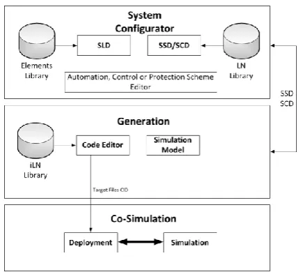
As mentioned previously, the flexibility of the IEC 61850 systems engineering process and the supporting configuration SCL files allows SysGRID to perform the role of both the system configurator and the device configurator. The architecture of the SysGRID tool is shown on Figure 4, SysGRID consists of three main modules. Module 1 is the system configurator, module 2 is the generation module and module 3 is the co-simulation module.
The first module is the IEC 61850 system configurator. As a system configurator, SysGRID is able to edit and produce SLD and SSD/SCD configuration files. Using a database of symbols, the SLD can be designed in the SLD
Figure 4. SysGRID architecture. Figure 2. Generation of automation, control and
SysGRID: IEC 61850 and IEC 61499 Standard Based Engineering Tool for Smart Grid Automation Design
to easily sketch automation, control and protection schemes on top of the SLD as if using paper. This functionality is implemented in the schema editor.
The second module is the Generation module, which enables SysGRID to parse the system design to identify physical components, functions and function interactions. Using a database of iLNs either pre-made or automatically generated from the DataTypeTemplate section of the SCL file, SysGRID can generate an executable IEC 61499 application directly from the specification. The code editor allows modification of the generated user-defined automation, control and protection logic. In addition, SysGRID generates the corresponding system configuration with the defined network topology and device set. Signal engineering while allocating functions to devices (distribution of functionality to IEDs) is supported by automated configuration of the detailed data flows between IEDs and allocation of communication addresses (GOOSE datasets, signal inputs to clients, sub-networks). In addition to importing SCL files, SysGRID can also be used to export SCL files. One example is the CID files which contains the necessary information from the SCD file of the designed system in order to configure the IEDs on an IEC 61850 compliant communication stack. SysGRID can also generate the target files and program files for the target IEDs and automation controllers.
The third module is the co-simulation module. In the co-simulation module, SysGRID performs functional simulation of the designed control logic in conjunction with the utility model. The automation, control and protection code can be downloaded to the simulated devices or deployed to real hardware. The tool provides a real-time, event-driven simulation via a GUI, e.g. an engineer can introduce a phase-to-ground fault into the model of distribution network. Additionally SysGRID supports hardware-in-the-loop testing with a controller, protection device or other equipment. The developed and validated code now can be deployed to the hardware.
5. Case Study: Distributed Protection
Application Design
The case study used to demonstrate the SysGRID tool is the distributed protection scenario adopted from [11]. The distributed protection schemes include distribution bus, selective backup and sympathetic trip protection. Each protection scenarios is designed with IEC 61850 in mind. This means the protection is carried out in a distributed manner with multiple IED devices collaborating to protect the system. This case study is an ideal scenario to demonstrate SysGRID as it highlights both the distributed design methodologies of an IEC 61850 and IEC 61499 based systems.
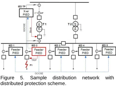
The power system distribution network used in the case study is shown in Figure 5. The network consists of distribution buses, two transformers and five feeders. The transformer protection IED (IED TP) is located at transformer T1, tripping the associated circuit breakers. Each feeder has a feeder protection IED (IED1 - IED5) and a circuit breaker to clear faults on each of their feeders. The protection scenario demonstrated in this case study is the sympathetic tripping scenario, but firstly, a quick overview showing how SysGRID can be used to generate the function block protection control of the case study protection control is presented.
The first step in the SysGRID design tool is to design the substation SLD and specifying the requirements for the desired protection schemes. Figure 6 shows the SLD for the case study power distribution network and the functional specification represented as logical nodes. The current transformer logical node TCTR is used to measure the current readings of their respective buses and feeders. The overcurrent protection is modelled with the instantaneous overcurrent logical node PIOC and it is placed in the bays area of the. Protection trip conditioning, needed for multiplexing signals from three protection schemes, is modelled with PTRC (Trip Conditioning) logical node. Interlocking functions are modelled with a CILO logical node and are also placed in the transformer bay. Circuit breakers are modelled with XCBR LNs controlled by CSWI switch control LNs. Note that the logical nodes XCBR, CSWI and TCTR are mostly equipment requirements and thus is placed next to their respective symbols on the SLD. The logical nodes PIOC and CILO are functional requirements and are thus placed on the bay level.
The next stage in the design process is the detailed engineering design stage and the resultant configuration is captured in the SCD file. The complete system configuration of the case study distribution network is shown on Figure 7. The SCD file defines the configurations of the IED devices and the assignment of the logical nodes functionality to the IED devices. As shown in Figure 7, the system is called S1 and there are five feeder IEDs and one transformer IED.
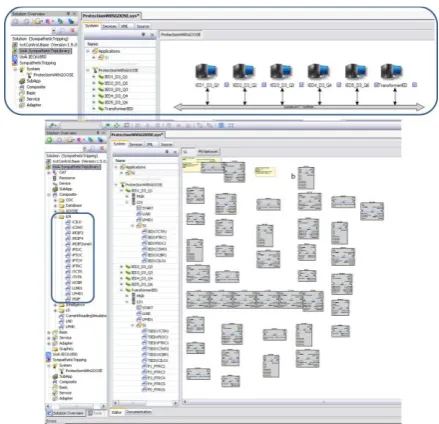
Having defined the system configuration, the next step is to automatically generate the IEC 61499 system configuration and code the protection logic. Figure 8 demonstrates the process in which the function block network is automatically generated from the SCD system configuration. For each LN instantiated in SCD file, an equivalent iLN will be automatically generated. Once the iLN function blocks are generated, the internal logic of the iLN can then be coded.
The complete function block network automatically generated from SysGRID is shown in Figure 9. In accordance with the mapping rules previously described, the function block network comprises an application called S1, six devices (5 feeder IEDs and 1 transformer IED) and the subnetwork for the control system. Each feeder has 8 LNs including the LN0 and the LPHD logical nodes, which are mandatory in an IEC 61850 device. The LN0 logical node contains the configuration for the communication services while the LPHD captures the information of the physical IED device itself. The transformer has 13 logical nodes since the transformer needs to be able to actuate the circuit breakers of each of the feeders in accordance to the protection scheme. Thus 5 additional PTRC logical nodes are assigned to the transformer IED. The application view of the generated function block system is shown in Figure 9. It corresponds to an SSD file in which LNs are not yet allocated to IEDs. Since the imported SCL configuration file is an SCD file, the iLNs are also correctly allocated to the IEDs as specified in the SCD file.
Figure 6. Single Line Diagram of the distribution network with functional requirements as logical nodes.
Figure 7. Single Line Diagram with allocated IEDs and system configuration.
Figure 8. Automatic generation module of SysGRID.
SysGRID: IEC 61850 and IEC 61499 Standard Based Engineering Tool for Smart Grid Automation Design
The logical nodes function blocks that are automatically generated are iLN [6], which are composite function block made up of a database FB and an intelligence FB as shown in Figure 10. The database FB contains the data of the IEC 61850 LN. The intelligence block implements the automation logic of the LN. With SysGRID, one can either use iLNs having the functionality of off-the-shelf IEDs, or create iLNs having novel and/or advanced functionality as required for Smart Grid applications. The intelligence of the iLN named “iPTRC” of the logical node PTRC is depicted on Figure 10. This FB implements a simplified algorithm for protection trip conditioning. In the cast study scenario, the PTRC logical node merges the transformer protection trip signal and the trip signals from overcurrent protection IEDs.
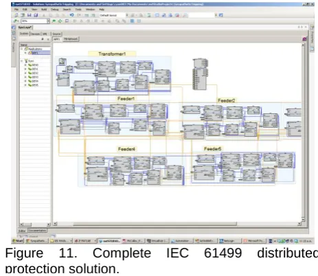
Using IEC 61499 event and data connections, the generated iLN function blocks can now be configured into a FB network performing the desired automation, control and protection functionality. In the use case example, each iLNs are inter-connected to perform distributed protection. Figure 11 presents the complete protection application ready for functional simulation.
The final step of the design process is testing and validation. For this purpose SysGRID offers an
environment for co-simulation of the application with the simulation model of the distribution network. The event driven close-loop co-simulation environment is shown in Figure 12. On the plant side, Matlab Simulink is used as the simulator for simulating the behaviour of the distribution network of the case study system. On the control side, the desired automation, control and protection logic is designed in IEC 61499 function blocks and simulated (executed) in SysGRID. During simulation, process data is exchanged between the Simulink model and the function block control model.
One of the test scenario used in the validation test of the case study is sympathetic tripping protection scenario [17]. In the Simulink model, a manual ground fault is inserted into the simulation model at feeder 2 as shown in Figure 13. The IED on feeder 2 and the transformer IED both detect the fault. At the same time, feeder 2 informs the neighbouring feeder IEDs that a fault was detected on its feeder via IEC 61850 Generic Object Oriented Substation Events (GOOSE) messages. This is a necessary step and shows the distributed nature of the protection scheme as this message prevents unnecessary tripping of both the transformer IED and sympathetic tripping by the adjacent feeder IEDs during the transient periods of the recovery process as inrush currents flow through the adjacent feeders.
6. Conclusion
With SysGRID the system engineering process can be easier, faster, resilient to human errors, optimized and Figure 10. iPTRC logical node architecture.
Figure 11. Complete IEC 61499 distributed protection solution.
Figure 12. Close-loop co-simulation for validating the generated control system with the plant model in Matlab Simulink.
more affordable than the current IEC 61850 system engineering process. In the current process a series of dedicated tools must be used, leading to a disconnected process in which incompatibilities between proprietary tools and their limited capabilities are detrimental to both speed and effectiveness. SysGRID was developed adopting the philosophy of system engineering from the IEC 61850, which was designed to minimize such problems. It does this by invoking a standards-based approach to re-usable engineering, thereby reducing engineering and implementation costs.
This tool addresses the design challenges of the Smart Grid, a complex system with distributed control. It aims to support Smart Grid system engineering, starting with requirements and arriving at executable code – a distributed software solution that is validated and ready for commissioning.
At this stage the tool is a prototype. Future work involves improving practicality and addressing design challenges, with the ultimate goal of producing a fully functional commercial product for use in Smart Grid solution engineering.
References
[1] X. Fang, S. Misra, G. Xue, and D. Yang, "Smart Grid - The New and Improved Power Grid: A Survey,"
Communications Surveys & Tutorials, IEEE, vol. 14, pp. 944-980, 2012.
[2] "Function Blocks—Part 1 Architecture, International Electrotechnical Commission," ed. Geneva: International Standard IEC61499-1, 2005.
[3] IEC 61850 - Communication networks and systems for
power utility automation, IEC Standard, Part 6: Configuration language for communication in electrical substations related to IEDs - Ed 2, 2009. [4] V. Vyatkin, IEC 61499 Function Blocks for Embedded
and Distributed Control Systems Design: ISA-Instrumentation, Systems, and Automation Society, 2007.
[5] N. Higgins, V. Vyatkin, N.-K. C. Nair, and K. Schwarz, "Distributed Power System Automation With IEC 61850, IEC 61499, and Intelligent Control,"
Systems, Man, and Cybernetics, Part C: Applications and Reviews, IEEE Transactions on, vol. 41, pp. 81-92, 2011.
[6] G. Zhabelova and V. Vyatkin, "Multiagent Smart Grid Automation Architecture Based on IEC 61850/61499 Intelligent Logical Nodes," Industrial Electronics, IEEE Transactions on, vol. 59, pp. 2351-2362, 2012. [7] (May 2012). CEN-CENELEC-ETSI Smart Grid
Coordination Group - Smart Grid Reference
Architecture. Available:
http://ec.europa.eu/energy/gas_electricity/smartgrids/d oc/xpert_group1_reference_architecture.pdf
[8] R. Santodomingo, J. A. Rodriguez-Mondejar, and M. A. Sanz-Bobi, "Ontology Matching Approach to the Harmonization of CIM and IEC 61850 Standards," in
Smart Grid Communications (SmartGridComm), 2010
[9] F. Andrén, M. Stifter, and T. Strasser, "Towards a Semantic Driven Framework for Smart Grid Applications: Model-Driven Development Using CIM, IEC 61850 and IEC 61499," Informatik-Spektrum, vol. 36, pp. 58-68, 2013.
[10] T. Strasser, M. Stifter, F. Andren, D. Burnier de Castro, and W. Hribernik, "Applying Open Standards and Open Source Software for Smart Grid Applications: Simulation of Distributed Intelligent Control of Power Systems," in IEEE Power & Energy Society General Meeting 2011, 2011.
[11] C.-W. Yang, G. Zhabelova, V. Vyatkin, N.-K. Nair, and A. Apostolov, "Smart Grid automation: Distributed protection application with IEC61850/IEC61499," in Industrial Informatics (INDIN), 2012 10th IEEE International Conference on, 2012, pp. 1067-1072.
[12] G. Zhabelova, V. Vyatkin, and N. C. Nair, "Standard-based engineering and distributed execution framework for intelligent fault management for FREEDM system," in IECON 2011 - 37th Annual Conference on IEEE Industrial Electronics Society, 2011, pp. 2724-2729.
[13] G. Arthurs, Model-Based System Engineering. Elements for Deploying an Efficient development Environment: telelogic. An IBM Company, 2008. [14] K. P. Brand, C. Brunner, and W. Wimmer, "Design of
IEC 61850 based substation automation systems according to customer requirements," 2004.
[15] T. Strasser, F. Andren, V. Vyatkin, G. Zhabelova, and Y. Chen-Wei, "Towards an IEC 61499 compliance profile for smart grids review and analysis of possibilities," in IECON 2012 - 38th Annual Conference on IEEE Industrial Electronics Society, 2012, pp. 3750-3757.
[16] C. H. Yang, G. Zhabelova, C. W. Yang, and V. Vyatkin, "Co-Simulation Environment for Distributed Controls of SmartGrid," Industrial Informatics, IEEE Transactions on, vol. PP, pp. 1-1, 2013.
[17] A. Apostolov and B. Vandiver, "IEC 61850 GOOSE applications to distribution protection schemes," in