Control law synthesis of the wind-driven power-plant
with variable geometry
V.A. Kostjukov
1,*, M.Y. Medvedev
2, N.K. Poluyanovich
1, M.N. Dubyago
3, D.I. Bulanovich
4and D.D.
Pavlenko
41 Associate Professor, Department of Electrical Engineering and Mechatronics, Southern Federal University, Taganrog,
Russia.
2
Head of Electrical and Mechatronics Department of the Southern Federal University, Taganrog, Russia.
3 Assistant of the Department of Electrical Engineering and Mechatronics of the Southern Federal University, Taganrog,
Russia.
4 Student of the Department of Electrical Engineering and Mechatronics of the Southern Federal University, Taganrog,
Russia.
Abstract
The analysis and synthesis of aerodynamic properties of the wind-driven power-plant (WP) construction with a vertical axis of rotation and useful interference of the stator and the rotor, that exceeds classical type analogues on energy characteristics, were conducted. The required functional dependence of the rotor rotative moment of WP on the angular speed of its rotation and the wind speed on the basis of aerodynamic optimization and researches of optimal shape and construction of WP was obtained. Respective aerodynamic power was calculated. The example of frequency stabilization of the rotor rotation through control of variable element of optimized form WP construction was considered. Method of maintaining the given angular speed of the rotor with a given deviation for a given time was proposed.
Keywords: aerodynamic optimization, wind-driven power-plant, synthesis, energy characteristic, interference.
Received on 22 October 2018, accepted on 16 February 2019, published on 21 March 2019
Copyright © 2019 V.A. Kostjukov et al., licensed to EAI. This is an open access article distributed under the terms of the Creative Commons Attribution licence (http://creativecommons.org/licenses/by/3.0/), which permits unlimited use, distribution and reproduction in any medium so long as the original work is properly cited.
doi: 10.4108/eai.13-7-2018.157036
*Corresponding author. Email:[email protected]
1. Introduction
The problem of increasing efficiency of existing wind-driven power-plants (WP) is considered in several articles [1-8]. A further task is to develop methods for designing WP constructions, the basic idea of which creation should be a sharp increase of efficiency of operation system of aerodynamically and electromechanical connected WPs compared to the corresponding set of unconnected WPs.
2. Possible development direction of
perspective type WP
reduces the losses caused by the flow separation on the blade tips [7, 14, 15]. Furthermore, using together with a ring also the output device (the bell) leads to a significant decrease of rotor minimum speed run of (to 45% of the wind speed). In [4], as well as in [6-7] WP using useful interference of the stator and rotor are studied. Vortical type WP [8] with a vertical axis of rotation is capable to reduce the power of hypersonic noise generation, arising from rotational moments on the side of the rotor axis. In the patent application [9] the vortex-type WP, which, in contrast to WP patent [8] has an additional guiding structure which contributes to a significant increase in rotor rotational moment, and a decrease in uneven distribution of pressure at the bottom rotor part is considered. Available WP allow only change the orientation of rotational rotor axis of WP to track wind speed vector. More appropriate is to manage due to the special variable geometry elements (VGE).
2.1. Aerodynamic optimization of WP
construction
WP development, using useful interference of stator and rotor, and VGE, requires solving the problem of analysis and synthesis of aerodynamic properties of WP construction, which comes down to an aerodynamic optimization of WP form and requires to use CFD-analysis (computational fluid dynamic).
For WP without VGE, as a criterion for optimizing the geometry, is advisable to choose maximum average P
on the range Q of all possible sets { , }V Q of values of useful power on the rotor:
,
max
geo opt geo geo
QU QU
U
P P
(1)
where the maximum search is performed on a given set of possible forms Ugeo of the rotor, the bell and their relative positions Ugeo opt, , - optimal in this sense WP geometry.
If WP contains both constructively immutable ( stat geo
U ), and a varied geometry ( stat
geo
U ), than in the first approximation, to simplify arising in such formulation problem of WP form optimization, the "static" of its component may be first optimized and ( , )
stat geo opt
U obtained, and then, based on the latest, solve the problem of VGE search ,
var geo opt
U , which deviation from its neutral position would ensure the specified objective qualities of WP as a whole.
As a result of aerodynamic optimization and subsequent full investigation of obtained optimum form and WP construction, the required functional dependence
( , )
MM V of WP rotational moment on two arguments: the angular speed
of the rotor and the wind speed vectorV were obtained3. Aerodynamic optimization
3.1
Example
of
aerodynamic
optimization.
Perform aerodynamic WP optimization, discussed in the patent [11]. Given: geometry of WP rotor, the initial version of the bell geometry and construction of the rotor [10].Rotor sizes: maximum diameter Dmax = 1.25m; height H =0.32m. Bell sizes: minimum (upper) diameter Drastrmin = 1,16m; maximum (lower) diameter Drastrmax = 2,23m; height H = 0,428m.
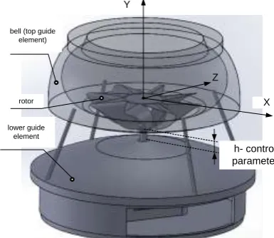
The range of wind load: V= 3 ... 30 m / s, the original range of angular speeds of the rotor rotation ω = 0,5 ... 20 rad / s. It is necessary to obtain optimal bell form, for a given rotor form and the corresponding constructing of obtained bell with the rotor, ensuring the implementation of the criterion (1) As a result of the aerodynamic optimization optimal from the point of view of given criterion and given set of basic forms of bell geometry and construction of the rotor are obtained (Fig. 1.) [16].
rotor
lower guide element bell (top guide
element)
X Y
Z
h- control parameter
Figure 1. WP construction of optimized bell with rotor.
3.2 Сfd-analysis of the optimal form WP.
Typical pressure distribution are obtained in the plane OXY at a flow rate of V = 10 m / c, angular rotor speed w = 6,28 rad / s for three cases: rotor without bell (2a), rotor with the initial bell (2b) and optimized (2c) forms (Fig. 2.).
b) for the initial construction «rotor+bell»
c) for optimized construction «rotor+bell»
Figure 2. WP construction of optimized bell with rotor.
3.3. Calculation of wind power.
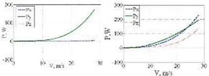
Fig. 3 shows diagrams of dependence of rotor rotation useful power to the OY axis (Fig. 1) and corresponding destabilizing rotation relative to OX and OZ axes for the cases of the original (left) and optimized (right) WP forms at
6,28rad / s
Figure 3. Diagrams of dependence useful Py and adverse Px, Pz of aerodynamic power from the
incoming flow rate V.
These graphs shows that by using optimized geometry (see. Fig. 1) in the wind speed range from 5 to 20 m / s useful aerodynamic power on WP rotor increases more than twice compared with the original WP geometry. Let us compare the energy efficiency of obtained optimized WP form with wind-driven power-plant of the Dnepropetrovsk CB "South", which has the power 500 kW at a wind speed 12.9 m / s, with the diameter of the screw D2 = 38,3 m [6]. To do this, define how much power would obtained optimized form WP have with the same size and speed of the wind flow, which for the considered analogue.
WP useful power can be calculated using the formula [17-21]:
1 ( , ) red gen
PM V (2)
where red ,
gen - the average values of of the gearbox and the generator efficiency, the values of which belongs to, as a rule, following ranges red0.9 0.95 ,0.7 0.9
gen
: [5].
If our installation has a diameter D2, than the rotational
moment, generated by it at speed Vw212,9 /m s and sufficiently small angular speed of the rotor
6, 28rad / s
.
3
22 1 2/ 1 w2/ w1 1034 kW
PP D D V V (3)
where with sufficient accuracy for practice suggested that the dimensionless coefficient of the rotational moment does not change at this scale.
Thus, if the rotor used in our apparatus, having diameter D2, than the corresponding optimized WP would have a power output more than twice exceed the power of WP-500 of Dnepropetrovsk "Southern".
This result shows that using optimized bell forms for special rotor forms with a vertical axis of rotation and is perspective and not inferior in increasing of efficiency wind using by other methods discussed, for example, in [1-8].
4. Adjusting mechanical parameters of
WP
During considering WP control the following tasks are raised: a) access to necessary angular speed of the rotor rotation for a minimum time; b) maintaining a predetermined angular speed of the rotor with a predetermined deviation for a predetermined time; c) maximization of wind energy generated by the rotor. As an example, for an optimized WP form obtained in p. 3 (Fig. 1), let's consider the solution of the problem of maintaining a given angular speed of the rotor within a predetermined range under wind speed perturbation. First of all, write the equation of rotational motion of WP:
( , , ) r , M h Vd
J M
dt
(4)
where M h V
, ,
- the dependence of the rotating axis aerodynamic moment of the rotor on the angular speed of its rotation , the wind speed V and the control parameter VGE Mr
; - moment of resistance to the rotor rotation that occurs at the contact it with the stator;J- reduced moment of the rotor inertia relative to the axis of rotation.
We assume that WP has one controlled geometry element - the lower guide structure characterized by variable geometry parameter - the distance from the top of the structure to the bottom of the rotor (Figure 1).
As external disturbances we will consider wind speed module V at its fixed direction as time function *
V t of aperiodic transition of speed perturbation:
*
0 Vexp V V
V t V t V A t sin t (5)
The inertia of the actuator VEG triggering, regulating the valueh, leads to the presence of a transient
process (TP), which occurs when establishing the objective function *
( )
h t . The latter is produced by the regulator, which we consider below. The specified TP with sufficient accuracy can be described by a differential equation of the first order:
*
( ) ( ) ( )
qh t rh t f t (6)
whereq and r - some constant coefficients, and the ratio
/
r q has the meaning of the decay time constant of the transition process, * * *
( ) ( ) ( ) f t qh t rh t .
It is necessary to find a control law h t
that providesdeviation of angular speed from the set nominal value
0 not greater than a predetermined limit max. Numerical investigation of this optimized WP form led to the following approximating according to aerodynamic moment on the shaft:
1 2 0
( , , )V V a a u h
M h VV f (7)
where the function f hu( ) is defined by the expression
1 1
3
4 1 2
2 2
, ;
( ) , ; ;
, ,
u
h при h h
a
f h a при h h h h
h при h h
(8)
and the constant coefficients in (7), (8) are
3 3
1 0,684 , 2 1,550 10 , 3 0,0921 ,
a Н s a Нs a
m m
4 0,858, 0 3 / , 1 0,02 , 2 0,65 a V m s h m h m.
Reproduced inertia moment assume to be equal to
2 m 100kg
J and resistance moment on the rotor shaft will be given by approximating dependence obtained based on studies WP vortex type described in [10]:
r
M b (9)
where b0,0019 Н m s .
Dynamic control range at the time (7) of rotation, ie, ratio of the maximum value of the time to a minimum by varying h isku2,7. The minimum value of control rangeh1 is due to technological limitations, and the maximum h2- leveling the aerodynamic effect of the lower guide structure WP rotor at a sufficient distance from its last.
Let tolerance for frequency deviation from the nominal value 6,28rad s/ is max0.3 rad s/ and
external wind disturbance, defined by equation (5), characterized by the values of coefficients
1
0 V V
V 5m s/ , A 1 / , m s V 0,5 s , Ω π rad /s
.
The regulation error 0 will be represented as a
first order equation [11]:
0,
T (10)
where T - the angular frequency transient time constant.
The regulation law will be obtained if we express from (10) and substitute into the equation of the rotor motion (4), and then express the controlled variable *
h :
3 1 2 00 *
1
0 4 1 2 0 0
, a V a a V V
h V
b JT a V a a V V
(11)
To obtain the real impact of VGE on the control object - the rotor, it is necessary to solve equation (6). This solution can be written in quadratures and then transformed after integration in parts to the following form [12]: / / * 0 0 * * 0
( ) 1 / ( ) ( ) (0) exp / , (12)
t
r q t r q t
h t q e e f t dt qh
h t h h r q t
(12)where h0h(0) - preset initial value h and taken into account that *
( )
f t associated with * ( )
h t by ratio
* * *
( ) ( ) ( )
f t qh t rh t according to (6).
The block diagram of the control parameter h for mechanical stabilization of the angular speed of rotation of the rotor is shown in Figure 4.
The driver forms the law of the angular speed of rotation variation 0under the influence of the measured current and voltage on the load and the target settings of the operator on the nature of the power supply of this load. Further, based on 0 and output 'of the angular speed meter rotor (encoder), an error signal is generated 0 ' 0 , coming to the regulator. The latter, under the influence and assessment V'V
of a wind speed meter V (anemometer), performs conversion est
,V considering the given objective function0. Output value* ( )
h t of regulator then fed to the block of the actuator VEG with a transfer coefficient
( ) 1 /
ed
K p qpr . Output of this blockh t( ), taking into account the inertia of the actuator actuation together with the current wind loadV , then directly affects on WP, which is reflected in the right side of the rotor state equation. The feedback of the control system is closes the next value of the rotor angular speed, arriving at the encoder, and then - at the adder.
Note that in the regulator empirical dependencies are used Mr( ), M h V( , , ) according to (7) and (9).
*
( ) est ,
h t V
1 ed K qp r ( ) h t __ Driving unit * ( ) h t
operator target settings
measured current and load voltage
Anemometer '( )
V t
Regulator Executive device
VEG ( )t
( )t
( ),t V V t( )
0
Encoder '( )t
Wind load
( )
V t
( , , ) с( )
J M h V M
Control object - WP, state control;
Figure 4 - Structural control scheme of the h- parameter for the mechanical stabilization of the angular speed of
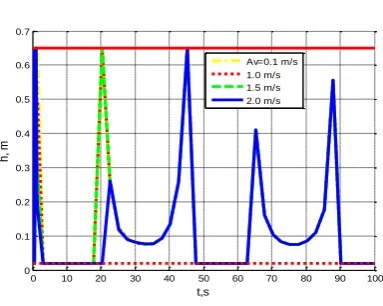
Figures 5 and 6 show diagrams of dependence and their respective departments from time with the initial conditionsh
0 0,5
h1h2
, , m
0 60,1, rad s/ for several values of the amplitudes of the oscillations of the windAV: dashed curve – for AV0,1 /m s; point - 1 m / s;dashed - 1.5 m / s; solid - 2 m / s. It was set T = 0.1 s.
Figure 5. Diagrams of dependence( )t for several values of the amplitudes of the wind
oscillationsAV.
Figure 6. Diagrams of dependence h t
for several values of the amplitudes of the windoscillationsAV.
The graphs given in Fig. 5, shows that for a given dynamic range control ku2,7stabilization of rotor speed with a given accuracy max0.3 rad s/ possible with the
amplitude of oscillation of the wind speed of at least satisfying AV 1,5 m / s. At the maximum speed
0,2 /
V
A m s corresponding to the function ( )t exceeds the permissible range maxby 50%. The graphs given in Figure 6, shows that during the first 30 seconds of the deviation curves h t
for different AVfrom each other are not visible, because according to (5) of wind fluctuations from time present an exponential factor exp
0,5 t
. The functions h t
are not smooth around the time range as a result of their forced cut-off when the limit values1, 2
hh h according to (8). To increase the range of
oscillation amplitudes A hV of wind perturbations, where possible to stabilize the rotational speed, it is necessary to increase the dynamic range regulation ku byh, or to
increase the maximum allowable deviationmax. The
introduction of additional elements of variable geometry can improve the dynamic range of rotative moment control.
The considered control of the mechanical speed of rotor rotation allows, firstly, to regulate the power at the load, limiting it at the right moment; secondly, to stabilize the electrical frequency at the generator output, thereby reducing the ripple coefficient at the rectifier output. The latter possibility is certainly important for the battery and inverter correct operation of WP electrical system. As a result, WP efficiency is increased; the allowable dynamic range of wind loads and the quality of generated electricity are expanded.
5. Conclusion
It is shown that WP construction on the basis of useful interference of stator and rotor is promising. Analysis of WP form with vertical axis of rotation, axisymmetric stator and rotor resulting from aerodynamic optimization [14] showed that the usage of useful interference of rotor and stator, on power characteristics superior to classical WP.
Using variable geometry elements significantly contributes the efficiency and adaptability [11] control system by output WP characteristics, expands the dynamic range of moment control on the WP rotor.
Acknowledgements
This work was supported by the RFBR grant No. 1-KV-1- 2018-18-08-00473 “Development and research of methods for optimizing and managing energy conversion processes in power plants of a complex type, including those that convert a continuous medium flow.
References
[1] Qing'an Li, Junsuke Murata, Masayuki Endo, Takao Maeda, Yasunari Kamada. Experimental and numerical investigation of the effect of turbulent inflow on a Horizontal Axis Wind Turbine (part II: Wake characteristics)./ Energy, Volume 113, 15 October 2016, Pages 1304–1315.
[2] Lin Wanga, Xiongwei Liub, Athanasios Koliosa. Renewable and Sustainable Energy Reviews, Volume 64, October 2016, Pages 195–210.
[3] Haskin L.Y. Aerodynamics propeller with a fairing and an output device. – Scientific notes of Central Institute of Aerohydrodynamics1993, t.24, №4.
[4] Mikhnenko L.V. Planetary type wind-driven power-plant.//Scientific Bulletin MSTU, №125, 2008.
[5] Gorelov D.N. Energy characteristics of the rotor Darrieus (review); 325-333.- Publisher Siberian Branch of the Russian Academy of Sciences (2010).
[6] P. Ying, Y.K. Chen, Y.G. Xu,Y. Tian Computational and experimental investigations of an omni-flow wind turbine. Applied Energy, Volume 146, 15 May 2015, Pages 74–83.
0 10 20 30 40 50 60 70 80 90 100 18.5
18.6 18.7 18.8 18.9 19 19.1 19.2 19.3 19.4
o
m
e
g
a
, r
a
d
/s
t,s
Av=0.1 m/s 1.0 m/s 1.5 m/s 2.0 m/s
0 10 20 30 40 50 60 70 80 90 100 0
0.1 0.2 0.3 0.4 0.5 0.6 0.7
h
, m
t,s
[7] A.D. Peacock, D. Jenkins, M. Ahadzi. A. Berry, S. Turan, Micro wind turbines in the UK domestic sector Energy and Buildings, Volume 40, Issue 7, 2008, Pages 1324–1333. [8] RF Patent № 2552635. (from 8 May 2015.) The device for
converting kinetic wind energy into mechanical energy. / Savchenko VV, Stepanov VS Published 10.06.2005 BI number 16.
[9] An application for a utility model patent, application number "device converting kinetic wind energy into mechanical energy using the lower guide structure" / Kostjukov V.A., Medvedev M.Y., Majewski A.M., Poluyanovich N.K., Savchenko V.V., filed 08/06/2016, at qualifier F03D3 / 04 IPC.
[10] G.A. Oborskiy, B.A. Wink, A.N. Bundyuk. The methodology of calculation of propeller blade with a self-adjusting - Pratsі Odeskogo polіtehnіchnogo unіversitetu, 2014. Vip. 2 (44).
[11] Pshihopov W.H. Mathematical models of robotic manipulator: Textbook. Taganrog: Publishing House of TTI SFU, 2008. 117 p.
[12] Matveev N.M. Methods of ordinary differential equations integration. M: High School, 1967. - 564 p.
[13] Bulanovich D.V., Sevast'yanov N.D., Poluyanovich N.K. Development of a wind turbine installation with a vertical axis of rotation. In the collection: Problems of automation. Regional Office. Communication and Automation (SAILS-2017) is a collection of works of the VI All-Russian Scientific Conference of young scientists, graduate students and students. Editorial Board: O. A. Fomenko, S. V. Kirilchik, A. Ya. Number. 2017. p. 219-225.
[14] Kostjukov V.A., Maevskiy A.M., Poluyanovich N.K., Dubyago M.N. Adaptive mechatronic management system of wind-driven power-plant with variable geometry. In the collection: International Conference of Young Specialists on Micro/Nanotechnologies and Electron Devices, EDM 2017. p. 460-464.
[15] Kostjukov V.A., Maevskiy A.M., Poluyanovich N.K. The method of rotor speed regulating of a wind power installation by controlling the variable geometry elements. In the collection: Fedorov readings - 2016 XLVI International Scientific and Practical Conference with elements of a scientific school (Moscow, November 16– 18, 2016). Under total ed. B.I. Kudrina, Yu.V. Matyunina. 2016. p. 255-263.
[16] Kostyukov V.A., Medvedev M.Yu., Mayevsky A.N., Poluyanovich N.K., Savchenko V.V. Investigation of a promising wind power plant with the “Rotor in a bell” arrangement type. Bulletin of the Don State Technical University. 2017. V. 17. № 1 (88). p. 85-91.
[17] Kostyukov V.A., Mayevsky A.M., Poluyanovich N.K., Dubyago M.N. Development of the theory and methods for improving the efficiency of the wind power plant with variable geometry aerodynamic power . In the collection: Modern problems of radio electronics and telecommunications "RT-2017" Materials of the 13th international youth scientific and technical conference. Ed. A.A. Savochkina. 2017. p. 179.
[18] Kostyukov V.A., Medvedev M.Yu., Poluyanovich N.K., Dubyago M.N., Savchenko V.V., Kovaleva A.A. Development of multiply connected control systems for rotar type wind turbines in the tasks of highly efficient energy production. In the collection: Vibration processes in the technology of processing parts of high-tech products. Collection of works of the international scientific symposium of industrial engineers. 2017. p. 199-204
[19] [19] Kostyukov V.A., Medvedev M.Yu., Mayevsky A.M., Poluyanovich N.K. Energy-efficient adaptive control system of a wind power plant with variable geometry. In the collection: Technologies for development of information systems TRIS-2016 conference materials: in 2 volumes. 2016. p. 191-199.
[20] Vitorovich V.V., Kostyukov V.A., Poluyanovich N.K. The choice of electric drive for industrial robotic arm. In the collection: Educational robotics in the scientific and technical creativity of schoolchildren and student youth: experience, problems, and prospects Materials of the 3rd All-Russian Scientific and Practical Conference with international participation. Executive editor N.V. Zelenko. 2017. p. 21-25