* To whom all correspondence should be addressed.
Simulation of Surface Intensification of Heat Exchange
in Shell-and-Pipe and Heat Exchanging Devices
Rinat Shaukatovich Misbakhov1, Victor Mihaylovich Gureev2,
Nikolai Ivanovich Moskalenko1, Andrey Mihaylovich Ermakov2
and Ilyas Zul’fatovich Bagautdinov1
1 Kazan State Power Engineering University, Russia, 420066, Kazan, Krasnoselskayast., 51. 2Kazan National Research Technical University Named After A.N. Tupolev,
Russia, 420111, Kazan, Marx st., 10. doi: http://dx.doi.org/10.13005/bbra/2228
(Received: 25 July 2015; accepted: 01 September 2015)
Decrease of material consumption of heat exchanging equipment is a topical problem, which can be solved by various methods. The most widely spread method is application of heat exchange intensifiers, which allow to increase heat flow in a pipe bank in 20-30%, depending on flow condition of a heat transfer agent, while remaining the same dimensions. Ring and helical knurls, as well as dimple notches are the most widely used for intensification for heat exchange. The most manufacturableknurl is a ring knurl, which can be easily applied on pipes and only minimum number of elements is needed. On a basis of the results of analysis of existing intensifier of heat exchange the authors propose the new type of knurl –semiring. That type of intensifier is also simple like a ring curl, but is presumably has lesser hydraulic resistance. The study presented the results of the numerical simulation of shell-and-pipe of heat exchanging device with application of helical, ring, dimple notches and semiring notches. Also, values of coefficients of heat transfer, heat flow, flow structure and pressure losses in pipes and casing at various flow conditions are obtained. Use of intensifiers leads to increase of heat flow for a whole range of flows of a heat transfer agent. The largest effect can be achieved by means of application of ring intensifiers, but they also lead to the biggest increase of hydraulic resistance. The main advantage of semiring intensifiers is ease of manufacturing and lesser number of elements of intensifiers as compared with dimple notches. Use of semiring notches allows to increase heat dissipation for a whole range of flows as compared with a smooth pipe, also it is recommended to use semiring notches instead of ring for big flows of a heat transfer agent due to lower hydraulic resistance as compared with a ring knurl for all flow conditions.
Key words: Intensifier, Heat transfer, Simulation, Heat exchange, Flow structure.
All produced thermal energy in all world countries 2-3 times transfered in various heat exchanging devices (HED) before its use. Therefore efficiency during production, transmission and use of energy (not only heat, but also electric) directly depend on efficiency of heat energy equipment and heat technological equipment, including HED. Problem of increase of efficiency and decrease of
dimensions of HED, generally, can be solved by means of new prospective methods of intensification of heat exchange in HED and use of new schemes of HED. Number of papers on that topic continuously grows. However, results of those studies are ambiguous. Selection of intensification methods is not always justified and often random.
part of HED consist pf pipe surfaces of heat exchange. For wide industrial application of shell-and-pipe heat exchangers it is reasonable to use intensification of heat exchange by means of artificial discreet roughness, which is formed on walls of channels at stages of manufacturing or finishing.
Design of the major part of HED used in the mentioned industries heat from a hot heat transfer agent to cold one is transfered through an intermediate body (wall). At that, a hot heat transfer agent transfers heat from one surface to another, and a cold one take it from other surface of a wall, i.e. for all cases heat exchange is carried out between a heat transfer agent and a heat exchange surface. That’s why technical and economical parameters of HED of all types and purposes are defined by a validity of solutions accepted during design of macro and microstructure of a heat exchange surface. Generally, it is true for shell-and-pipe, pipe-and-ribs, plate, plate-and-ribs and other types of regenerative HED.
About 80% of all used HED belong to shell-and-pipe type. Therefore, studies in a field of shell-and-pipe HED is of the greatest interest. All existing and prospective power energy equipment of steam-turbine equipment, gas-turbine equipment, combined cycle equipment and nuclear
power equipment, as well as renewable energy equipment, heat exchanging equipment amounts for a main or a significant part in terms of dimensions, metal consumption and functions; in many aspects it determines general technical and economical parameter of equipment. Therefore, nowadays and in future, one of thee main, technically and economically the most affordable and reasonable ways to increase the cost-effectiveness of energy equipment is improvement of heat-exchange equipment, which can be achieved by means of application of effective methods for intensification of heat exchange.
In recently there was a certain development of shell-and-pipe heat exchangers. In some cases application of devices for creation of artificial turbulence on pipes (e.g., windings or knurlings) provides forced separation of a boundary layer of product from a heat transferring wall, which significantly intensifies heat exchange. If necessary (e.g., for inspection, cleaning or repair) a bank can be easily taken out from a casing. That kind of heat exchanger designs completely excludes contact between both media. New capabilities of pipe heat exchangers allowed to use them in regenerative equipment, in which plate type heat exchangers were regularly used.
Fig.1. Sizes of notches
a) helical notches; b) semiring notches;
Roughness elements, for example, protrusions, increase turbulence of a wall zone of a flow and stimulate a heat transfer process near a wall. Intensification of a heat transfer allows to increase quantity of heat, which is transfered through a unit of a heat exchange surface area. Therefore, it allows to reduce weight and dimensions of a heat exchanger. Industrial production of channels with intensified heat transfer by means of artificial roughness, for example, pipes with regularly positioned periodic transversal ring protrusion along and internal surface of a pipe, from a point of view of manufacturing, can be the most easily provided by means of knurling. As a result, internal surface of a pipe will be covered by ring notches, which intensify heat transfer in a casing; also, helicalknurlings are used, as well as dimple notches, which are introduced recently.
However, it is necessary to take into account one important point. Values of saving on energy and materials, which were calculated during comparison of hear exchangers, are for the same
velocities of flow of a heat transfer agents in channels of smooth (mass produced) and intensified HED. The mentioned condition, in particular, correspond to the situation with modernization of existing HED due to introduction of intensified channels. In a case of design of new intensified HED, when design engineer is not restricted in a selection of speed of HED, saving can increase in several times. Therefore, in the presented paper we studied thermal efficiency depending on flow conditions.
It is necessary to take into account shape and size of intensifiers, as well as feature of flow conditions of a heat transfer agent, moreover, various intensifiers has various technological efficiency during manufacturing and application, and in a case of a simple technology HED in a whole becomes cheaper. Rationally selected parameters of heat exchange intensifiers provide better ratio between transfered quantity of heat Q and power of pumping of a heat transfer agent N in an intensified device as compared to a device with smooth pipes.
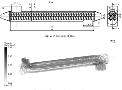
Fig. 2. Dimensions of HED
Experience of development and operation of various HED demonstrated that already existing methods for intensification of heat exchange allow to decrease dimensions in 1,5...2 times as compared to same mass produced devices with the same thermal capacity and power for pumping of a heat transfer agents.
Roughness elements, for example, protrusions, increase turbulence of a wall zone of a flow and stimulate a heat transfer process near a wall. Intensification of a heat transfer allows to increase quantity of heat, which is transfered through a unit of a heat exchange surface area. Therefore, it allows to reduceweight and
dimensions of a heat exchanger. Rationally selected parameters of heat exchange intensifiers provide better ratio between transfered quantity of heat Q and power of pumping of a heat transfer agent N in an intensified device as compared to a device with smooth pipes. Therefore, it leads to increase of energy coefficient of intensified heat exchanger
E = Q / N
which is the main parameter of efficiency (thermal, hydraulic and economical) of HED. At that, energy saving effect, i.e. saving on electric energy or fuel used by a power equipment. Taking into account necessity of energy saving, it should be considered that use of heat transfer
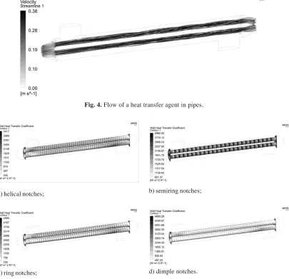
Fig. 4. Flow of a heat transfer agent in pipes.
Fig. 5. Heat dissipation coefficient at an external surface of pipes. a) helical notches; b) semiring notches;
intensification in newly designed equipment is reasonable only in a case, when E >Es , á > ás, where á, ás – heat dissipation coefficients for intensified and smooth channels. Therefore, the main problem of design of an intensified HED is search for a device meeting the condition E = E max > Es.
High energy saving capabilities of discreetly rough channels, their capability to provide significant saving on structural materials, good dimensions and weight of modern heat exchangers and wide field of HED, in which it is reasonable to use intensified banks of pipes clearly demonstrate economic need for fast and wide implementation of channels with transversal protrusions. Increase of technical and economical parameters of energy equipment due to implementation of pipes with knurled protrusions is inexpensive technology with short payback period. It is especially important at the current stage of development of energy sector in Russia, when fuel and energy industry is in a stage of serious economy crisis and experiences deficit of investments.
For intensification of heat exchange in shell-and-pipe HED both notches with ring shape of various types and notches with sharp edges of various geometry. In the study1 the easiest and
the least expensive in production ring, helical and dimple notches are discussed taking into account deformation of metal during their manufacturing. As a result of analysis of leading researchers in a field of surface intensification: Olimpiev V.V., Kalinin E.K., Dreitzer G.A., Gort’shovYu.F. and Popov I.A2-10 and other authors10-17 the optimum
sizes for ring, helical and dimple notches are selected, and new type of intensifiers –semiring is developed.
It is known that summarization of many experimental results in a maximum case of roughness showed a possibility of conformity of resistance laws for channels with transversal protrusions in a case of smooth profile and in a case of sharp edges of protrusions’ cross-section (for the same t, h). From laws of resistance it can be concluded that resistance of channels with smooth profile of protrusions and with protrusions having sharp edges is decreasing with increase of protrusions’ height. Theoretically, evaluation of coefficient of resistance of protrusion Õ in turbulent
flow for big values of Re, when influence of viscosity decreases, shows that shape of profile doesn’t influence Õ value. In that case it depends only on geometry parameter d/D. That point is proved in a number of experimental works.
It should be noted that even in a case of reasonably selected height of protrusions independently on flow conditions of a main flow in a channel (turbulent of laminar) for the same values of step h /t =1.5-5 it is possible to achieve the condition of decreased heat dissipation á d” ás. That fact proves that natures of flows in intensified channels for both laminar and turbulent flow have many common points.
Thus, in conditions of laminar and turbulent flows in channels with protrusions in previous studies there are a number of experimentally proved facts of specific influence of h / t parameter on dynamics of flow and heat transfer. Conditions, causes and mechanisms of that influence are unknown. It is necessary to analyze available information not only from a point of view of channels and protrusions, but also for other systems, in which flow is quite similar to a flow in intensified channels.
The aim of the presented study is simulation of heat exchange process directly in HED, establishing of relationships between heat dissipation of heat transfer agents and flow conditions, both in pipes and in a casing.
Moreover, another aims of the work are study of flow structure, hydraulic resistance and heat dissipation with visualization of flow in constrained and not constrained channels in order to clarify physical parameters of flow and to develop basics of a flow conditions’ map, identification of influence of main geometry parameters and flow condition’s parameters on hydraulic resistance, heat dissipation, as well as comparative analysis of thermal and hydraulic efficiency of various surface intensifiers, including establishing of optimal parameters of flow conditions and geometry of intensifiers. The main geometry parameters of intensifiers are presented in Fig.1.
METHODOLOGY
a heat transfer agent both in pipes and in a casing, distribution of pressures and heat transfer coefficients at internal and external surface of a pipe bank. In the study we used ANSYS CFX software (certificate No. ANS2011-S015), which is successfully used for solution of problems in that field.
As a model of HED we used water-to-water heater with the following parameters: number of pipes – 4, diameter of pipes – 16 mm, diameter of casing – 57 mm, length – 500 mm. Heat transfer agent’s flow scheme – counter-flow. Working medium – water-to-water. Design model of HED is presented in Fig.2. Flow of a heat transfer agent was measured simultaneously in pipes and in a casing in a range from 0.1 to 0.7 kg/s with 0.1 kg/s step. Initial temperature of cold heat transfer agent at input of pipes – 8°C.Initial temperature of hot heat transfer agent in casing – 95°C. As the problem is symmetrical for calculation we used half of HED and set up symmetry condition.
Finite-element model of HED consists of three calculation domains: water in a pipe bank, pipe bank and water in a casing. Calculation mesh is tetrahedral, moreover, for liquids we used prismatic mesh with 10 prismatic sublayers. Number of finite-element noes in one mesh was about 30 mln. for one presented calculated model. In practice, HED most frequently use turbulent flow conditions of a heat transfer agent,
therefore, for solution of the problem we selected SST (Shear Stress Transport) model of turbulence, which allows to obtain the most accurate solutions of that kind of engineering problems.
RESULTS
Flow structure in the casing of HED is presented in Fig.3. It is similar for all discussed cases of intensifiers and differs insignificantly in true values of velocities and pressures. From analysis of flow structures it is clear that flow is non-uniformly distributed along cross-section of heat exchanger, and the major part of flow passes through the upper part of HED. Also it is visible that flow is pressured towards the wall at output of HED
Inside a pipe bank in a case of application of helical knurling there is twisting of fllow along a whole pipe’s length(Fig. 4).
Fig. 5 shows heat dissipation coefficients for internal and external surface of heat exchanger pipe for a case of application of helical and semiring notches
Analysis of maps of heat dissipation coefficients allows to asses uniformity of heat exchange intensity along length of pipes of HED, where heat dissipation coefficient for smooth pipe is about 828 W/(m2*K), for pipes with intensifiers
it is 1318-1592 W/(m2*K) for a case of flow of 0.1
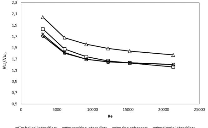
Fig. 8. Relationship between thermal and hydraulic efficiency and flow conditions.
Fig.7. Relationship between hydraulic losses and flow conditions in pipes. kg/s, which correspond well with physical
parameters of process and analytical relationships for those cases.
The biggest average heat dissipation coefficient along pipe surface is achieved in a case of ring notches: effect of their use is reaching 60% for low Re and 25 for big values of Re. Heat transfer for helical notches is lower than for a ring one, dimple notch and semiring notches have almost the same heat transfer coefficient. The coefficient in a casing for helical notches becomes comparable with a smooth pipe in a case of increase of a heat
transfer agent.
For comparison of thermal efficiency of various types of intensifiers on a basis of experiments, which were carried out by various authors for various average temperatures of flow of media and for various ranges of Re, it is possible to use the equation (1)18, which characterizes
)
Re
(
)
(
Nu
Nu
0=
f
...(1)From analysis of Fig.6 it can be concluded that efficiency of application of intensifiers is decreasing with increase of Re. As it known, application of any of known methods of intensification of convective heat exchange is accompanied by increase of hydrodynamic resistance, which is one of the main parameters influencing expenditures of energy and power, which is necessary for pumping of working media through HED.
Hydraulic losses depending on flow conditions in a pipe bank of HED are presented in Fig.7.
Therefore, for comparison of full thermal and hydrodynamic efficiency of various types of intensifiers it is often reasonable to use the equation (2), which characterizes relative increase of heat exchange intensity in a pipe with intensifier on unit of additionally used energy18.
...(2)
Comparison of thermal and hydraulic efficiency is presented in Fig.8.
CONCLUSION
From the point of view of complex parameter of increase of heat dissipation to increase of hydraulic resistance, the highest efficiency is showed by dimple notches, the second are semiring, helical and ring intensifiers, but increase of thermal flow for a case of application of ring notches for small flows is 50%, for big flows 27.1%, for semiring notches for small flows of a heat transfer agent it is bigger as compared with smooth pipes in 42.3% and it is insignificantly lesser than helical notches for 5.2% with smaller hydraulic resistance of semiring notches in 6,5%. For bigger flows increase of heat flow for cases of semiring notches, as compared to a smooth pipe and helical notches, correspondingly, 16.6% and 3.5% with lesser hydraulic resistance of semiring notches as compared to helical ones for 20.4% and 42.4% – for ring notches.
The biggest effect of intensification in absolute values is achieved by means of ring intensifiers, but at the same time they produce the highest hydraulic resistance. Use of semiring and
dimple notches gives medium increase of heat flow and hydraulic resistance as compared to a smooth pipe. Use of helical knurling increases hydraulic resistance in a casing. Use of semiring intensifiers allows to achieve the same effect with dimple and helical notches, which is accompanied by ease of manufacturing and small number of elements. The study was carried out in a framework of a state research and development contract No.2014/448 (project code 2806). The results of the study can be used for development of high performance HED in energy sector and automobile industry19, 20.
REFERENCES
1 Kalinin, E.K., Dreitzer, G.A., &Yarho, S.A. Intensification of heat exchange in channels. 3rd
ed., rev. and ext. Moscow: Mechanical Engineering 1990.
2. Gortyshov,Yu.F.,&Olimpiev, V.V. Heat exchanging devices with intensified heat exchange. Kazan: Publishing house of Kazan national research technical university named after A.N. Tupolev 1999.
3. Gortyshov,Yu.F., Popov, I.A., &Shelchkov, A.V. Thermal and hydraulic efficiency of prospective methods of intensification of heat dissipation in channels in heat exchanging equipment.Center for innovative technologies 2009.
4. Olimpiev, V.V., &Mirzoev, B.G. Energy-efficient intensifiers of laminar heat transfer. Russian Aeronautics, 2013; 2(56): 185-190.
5. Olimpiev, V.V., &Mirzoev, B.G. Effectiveness of channels with heat transfer intensifiers in the form of protrusions. Thermal Engineering (English translation of Teploenergetika), 2013;
3(60), 182-189.
6. Leont’Ev, A.I., &Olimpiev, V.V. Analyzing the effectiveness of wall flow swirlers. Thermal Engineering (English translation of Teploenergetika), 2013; 1 (60): 67-77. 7. Popov, I.A., Shchelchkov, A.V., Ryzhkov, D.V.,
&Ul’yanova, R.A. Vortex generation in flows past differentially dimpled surfaces. Heat Transfer Research, 2012; 4(43): 285-295. 8. Olimpiev, V.V., &Mirzoev, B.G. A simple model
of heat exchange and friction in the channels with spiral near-wall flow swirlers. Russian Aeronautics, 2012; 3(55); 284-290.
1-12.
10. Olimpiev, V.V. Enhancement of heat transfer and the potential for energy conservation in industrial oil coolers. Thermal Engineering (English translation of Teploenergetika), 2010; 8(57): 702-713.
11. Leontiev, A.I., &Olimpiev, V.V. The effect of intensifiers of heat transfer on the thermohydraulic properties of channels. High Temperature, 2007;6(45): 844-870.
12. Isaev, S.A., Leont’ev, A.I., &Baranov, P.A. Simulating tornado-like enhancement of heat transfer under low-velocity motion of air in a rectangular dimpled channel. Part 2: Results of parametric studies. Thermal Engineering (English translation of Teploenergetika), 2007;
8(54), 655-663.
13. Olimpiev, V.V. Enhancement of heat transfer in type PM fuel oil heaters. Thermal Engineering (English translation of Teploenergetika), 2006;
11(53), 920-924.
14. Gortyshov, Yu.F.,&Popov, I.A. The scientific basis of calculations of highly efficient compact transfer apparatuses with judicious heat-transfer intensifiers. Thermal Engineering (English translation of Teploenergetika), 2006;
4(53): 249-261.
15. Leontiev, A.I., Gortyshov, Yu.F., Popov, I.A., Olimpiev, V.V., &Kaskov, S.I. Efficiency of surface heat transfer intensifiers for laminar and
turbulent flows in heat exchanger channels.American Society of Mechanical Engineers, Heat Transfer Division, (Publication) HTD 2006.
16. Leont’ev, A.I., Gortyshov, Yu.F.,Olimpiev, V.V., &Popov, I.A. Effective heat transfer intensifiers for laminar (turbulent) flow in energy unit channels.IzvestiyaAkademiiNauk. Energetika, 2005; 1: 75-91.
17. Gortyshov, Yu.F., Popov, I.A., & Usenkov, R.A. Heat transfer of free convective flows in the presence of surface intensifiers.IzvestiyaVysshikhUchebnykhZavedenij. AviatsionnayaTekhnika, 2003;3: 29-33. 18. NazmeevYu.G.,&Lav’igin V.M. Heat exchanging
devices of thermal power plants.Handbook for Higher Education Institutions.Moscow: Publishing house of MPEI 1998.
19. Gureev, V.M., Sosnovsky, A.P., Yunusov, R.R., Gureev, R.R., &Salahov, R.R. Modernization of production version of oil cooler for “KAMAZ” engine.Bulletin of Kazan national research technical university named after A.N. Tupolev, 2012; 3: 41-45.