Study of Hemi-Spherical Dielectric Resonator Antenna
with Change in Dielectric Characteristics of Resonator
Neeraj Kumar
Deptt. of Telecom technology & Management,
Amity institute of Telecom Technology &
Management, Amity University, Noida, India
Ajay Kumar Thakur
Deptt. of Physics
C. M. Sc. College, Darbhanga, Bihar
ABSTRACT
The paper presents the effect of relative permeability and relative permittivity on the behavior of a miniaturized antenna. The proposed design is combination of hemi-spherical antenna cavity and a hemi-spherical Dielectric Resonator substance; hence this radiating structure is called as hemi-spherical dielectric resonator antenna (HSDRA). Using the DRA, a volumetric source improves the radiation power factor of the radiating slot.[1] The antenna is designed and simulated on HFSS to effectively observe its far-field and near field radiation pattern and different characteristic parameters of antenna system such as gain, VSWR, return loss. The radiation patterns and fields including different characteristics are studied at 3.75 GHz.
Keywords
Hemi-Spherical Dielectric Resonator Antenna (HSDRA), Relative Permeability, Relative Permittivity, Far Field Radiation, Near Field Radiation, Gain, Return Loss
1.
INTRODUCTION
Antenna miniaturization is becoming increasingly important especially in wireless applications over a wide range of frequency. The demand for wireless technology has increased dramatically in the past decade. There is a huge demand of a small, efficient antenna which can be easily integrated into mobile devices. Alternatively, as the frequency of operation is lowered, miniaturization techniques must be employed to keep antenna size practical. [2] There are two primary techniques to achieve antenna miniaturization. The first is using novel topology to reduce the overall area consumed by the radiating structure.
The second is using materials with permittivity, permeability, or both, greater than one; since wavelengths inside such materials are reduced, the characteristic size of the antenna decreases.[3] This study uses the latter technique to achieve antenna miniaturization by employing a dielectric resonator as a superstrate for the antenna.
Truncating the dielectric superstrate yields a resonant structure called a dielectric resonator antenna (DRA). Dielectric resonator antennas are experiencing increased use in antenna applications due to favorable properties including low cost, inherently wide bandwidth, small size, and high efficiency due to the absence of conductors and surface wave losses.[4] They
permeability.[5] The current technique improves the radiation and power radiation of these antennas without compromising their efficiency and other positive characteristics.[6-7]
2.
DESIGN AND CONSTRUCITION
The antenna is an annular-slot coaxial fed hemi-spherical dielectric resonator. The design’s operating frequency is 3.75 GHz. Antenna simulation and observations has been performed in three stages.2.1
Standard Observations
In first condition, a practical antenna has been simulated keeping relative permittivity ε = 1 and permeability χ = 15 of the resonator material.
2.2
Effect of Change in Relative Permeability
The resonator is then chosen to be encompassed of a material having the same permittivity as the first case and χ = 30. The two cases clearly illustrate the effect of modification in relative permeability of the material.
2.3
Effect of Change in Relative Permittivity
Finally, keeping the permeability same as in second case, we increase the permittivity of the material ε = 15 to study the upshot of change in relative permittivity of the material comprising the resonator. The far and near field polar plots, their corresponding radiation patterns, s-parameter of impedance and the VSWR response with change in frequency is obtained in graphical form.
3.
SIMULATIONS
This section gives the simulation results obtained using HFSS v10 (High Frequency Structure Simulator) software program, when the dielectric characteristics of material of DRA was varied.
3.1
Simulation Result with DRA Material Having ε
= 1 and χ = 15
Figure 1 3-D Polar Plot of Far Field
Figure 2 3-D Polar Plot of Near Field
Figure 3 Near Field Radiation Pattern
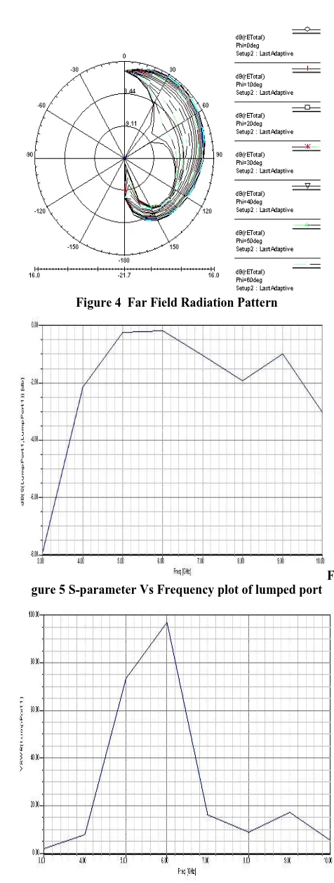
Figure 4 Far Field Radiation Pattern
Fi gure 5 S-parameter Vs Frequency plot of lumped port
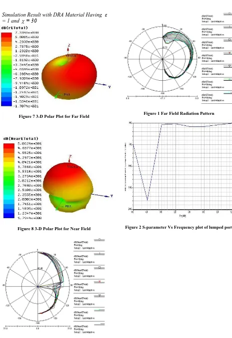
3.2 Simulation Result with DRA Material Having ε
= 1 and χ = 30
Figure 7 3-D Polar Plot for Far Field
Figure 8 3-D Polar Plot for Near Field
Figure 1 Far Field Radiation Pattern
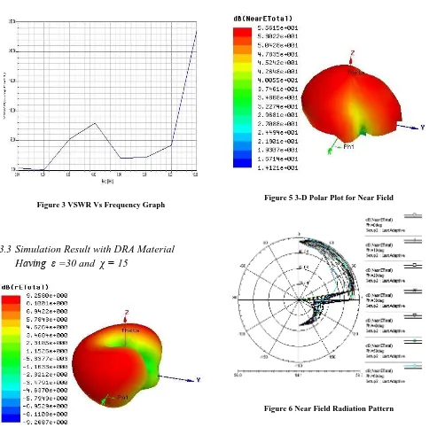
Figure 3 VSWR Vs Frequency Graph
3.3
Simulation Result with DRA Material
Having ε =30 and χ = 15
Figure 4 3-D Polar Plot for Far Field
Figure 5 3-D Polar Plot for Near Field
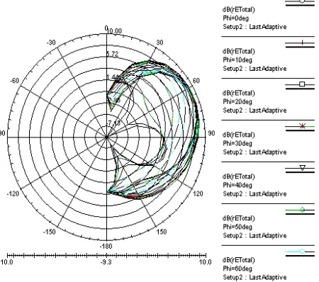
Figure 7 Far Field Radiation Pattern
Figure 8 S-parameter Vs Frequency plot of lumped port
Figure 9 VSWR Vs Frequency Graph
4.
DISCUSSION
The radiation and frequency response vary widely depending upon the dielectric characteristics of the material used to construct the DRA. As the relative permittivity and permeability of the material constituting the DRA increases, the size of DRA will decrease. Here, parametric study of the system has been performed by changing the relative permittivity and permeability of the radiating material constituting the DRA. Following are the findings for the simulated system:
i.
As the relative permittivity and permeability of the matter constituting the resonator increases, there decrease in the uniformity of the far field radiation pattern. The far field radiation pattern is considered at infinite sphere. From three dimensional polar plot of fig. 1 and 7, it is clear that when there is increase in relative permeability the uniformity in the radiation pattern is maintained, only there is change in the direction of the maximum and minimum radiation. But as the relative permittivity is increased as seen in Fig. 13, the radiation pattern is not uniform and the radiation pattern is more concentrated in the direction of theta and phi.ii.
The near field radiation pattern is considered at 20 mm sphere around the antenna system. It shows from fig. 2 and 8 that when there is increase in relative permeability the near field the radiation pattern is concentrated in the direction of theta and phi but as the relative permittivity is increased as seen in Fig. 14, the near field radiation pattern is concentrated in the direction of theta.iii.
As the relative permittivity and permeability of the matter constituting the resonator increases there is an increase in the near field radiation pattern of the resonator. The simulated result of DRA for different proposed values of dielectric characteristics of material constituting the resonator is presented in fig. 3, 9 and 15. These figures shows that when there is increase in the relative permeability of the antenna resonator the near field is hemi-spherically concentrated at the region of 20 mm sphere but as the value of relative permittivity is also increased the pattern changes and it remains confined only in the first quadrant.iv.
The far field radiation pattern increases with increase in permittivity but is widely dispersed (shown in Fig. no. 4 and 16). However, as the relative permeability of the DRA material is increased the radiation pattern of the antenna system is more concentrated at the infinite sphere (shown in Fig. no. 10).vi.
VSWR is specified as a maximum value for the frequency range of a component. Studying Fig. 6, 12 and 18, it is observed that the VSWR of the antenna is obtained at 6 GHz under initial conditions. With increase in permeability to almost twice the initial value, the ratio increases to almost twice than that in initial condition, with a significant rise in the frequency (10 GHz and increasing). Contrarily, when permeability is made constant, increasing the permittivity from ε = 1 to ε = 30 not only lowers the frequency to 5 GHz, but also the ratio is almost halved than in the initial condition.5.
CONCLUSION
It is deduced that, when the relative permeability, χ of the DRA is increased, the near-field patterns increases and the directivity of the radiation pattern changes. Far-field radiations of the antenna system also increases but become more concentrated at the region of infinite sphere, the VSWR increases, and the Return Loss along with the operating frequency decreases. Again, when the relative permittivity, ε of the DRA is increased, the near-field patterns increases similar to the increase when permeability was increased, far-field radiations too increases but become more disperse, the VSWR increases, and the Return Loss decreases significantly along with an increase in the operating frequency.
6.
REFERENCES
[1] Leung, K.W., So, K.K., “Annular-slot-Excited Dielectric Resonator Antenna with a Backing Cavity,” IEEE Transactions on Antennas and Propagation, August 2002.
[2] A. Kishk, Y. Yin, and A. Glisson, “Conical dielectric resonator antennas for wide-band applications,” IEEE Trans. Antennas Propag., vol. 50, no. 4, pp. 469–474, Apr. 2002.
[3] R. K. Mongia and A. Ittipiboon, “Theoretical and experimental investigations on rectangular dielectric resonator antennas,” IEEE Trans. Antennas Propag., vol. 45, no. 9, pp. 1348–1356, Sep. 1997.
[4] G. Junker, A. Kishk, and A. Glisson, “Input impedance of aperture-coupled dielectric resonator antennas,” IEEE Trans. Antennas Propag., vol. 44, no. 5, pp. 600–607, May 1996.
[5] A. Kishk, “Wide-band truncated tetrahedron dielectric resonator antenna excited by a coaxial probe,” IEEE Trans. Antennas Propag., vol. 51, no. 10, pp. 2913–2917, Oct. 2003.
[6] A. Petosa, N. Simons, R. Siushansian, A. Ittipiboon, and M. Cuhaci, “Design and analysis of multisegment dielectric resonator antennas,” IEEE Trans. Antennas Propag., vol. 48, no. 5, pp. 738–742, May 2000.