E 36 MECHANICAL ENGINEERING: Computational Mechanics JOURNAL OF ENGINEERING SCIENCES
ЖУРНАЛ ІНЖЕНЕРНИХ НАУК
ЖУРНАЛ ИНЖЕНЕРНЫХ НАУК
Web site: http://jes.sumdu.edu.ua DOI: 10.21272/jes.2019.6(2).e6 Volume 6, Issue 2 (2019)
Simulation and Optimization Studies on the Ring Rolling Process
Using Steel and Aluminum Alloys
Teja P. S.*, Kumar M. D., Krishna R., Sreenivasan M.
PACE Institute of Technology and Sciences, 523 272 Ongole, Andhra Pradesh, India
Article info: Paper received:
The final version of the paper received: Paper accepted online:
September 12, 2019 December 6, 2019 December 11, 2019
*Corresponding Author’s Address:
[email protected]
Abstract. The current research was carried out using ANSYS to optimize the process parameters for the ring ing process. In order to optimize the ring rolling process, parameters such as speed, axial roller feed, and driving roll-ers have been assessed. As a process optimization approach, the optimum values of the parametroll-ers and their relation-ships need to be evaluated. The stress and strain levels were evaluated at various speeds and forces and the critical failure values were determined. The structural steel and aluminum alloys were chosen for this research because they are used as a roller and job part components in the solid wheels for locomotive applications, respectively. The study was conducted by varying the guide roller's angular velocity from 40 to 45 rad/sec and varying the work piece’s an-gular velocity from 200 to 250 rad/sec. Additionally, the work part and roller’s fatigue strengths were determined based on the number of cycles before failure. To evaluate the stresses of plastic strain and von failures, the full stress analysis was also performed.
Keywords: roller, ANSYS, workpiece, plastic strain, von Misses stress, metal alloy.
1
Introduction
Rolling is a continuous metal shaping between a series of spinning or rotating rolls, whose shape or height is gradually decreased to produce the desired segment by applying strong plastic deformation pressures. It is the method of thickness reduction which reduces the length without significantly increasing the width. The ring roll-ing method can be carried out at high temperature (hot) or at ambient temperature (cold) with the product initially. Ring rolling is an innovative technique in the develop-ment of smooth rings of elastic cross-sectional form, enhanced grain structure, and reduced scrap. The ring is formed by a local continuum rolling method as shown in the figure from an initial void, incrementally from a small diameter and thick section to a wide diameter and thin section. In the area of metal plastic manufacturing, re-search and development of ring rolling techniques with rings complicated in form or wide in length or with high precision have become an important topic. Because of the process's nature and strong nonlinearity, it is difficult to describe the process correctly by analytical methods alone. Although quantitative explanations are appropriate for the system they are being based on, findings are chal-lenging to extrapolate accurately. The finite element ap-proach for researching and developing innovative ring rolling techniques is, therefore, inspired [1]. Developing a
realistic 3D finite-element ring rolling model has become an urgent issue, and the problem of how to properly mon-itor guide rolls is one of the key issues in achieving a good 3D finite-element ring rolling simulation, particular-ly for rings that are complicated in shape or wide in size or with high precision [2].
2
Literature Review
Some journal papers were selectively studied which have direct relevance with the current research work and their results are discussed here.
ele-Journal of Engineering Sciences, Volume 6, Issue 2 (2019), pp. E 36–E 40 E 37 ments. A fair quality scope of the rolling ratio is
calculat-ed bascalculat-ed on comparison and observational validation. To simulate the non-linear problem that characterizes the ring rolling process, finite element codes are available [4]. The analysis is done using ANSYS. The parameters including speed, axial roller feed, and driving rollers were analyzed from the study [5]. The optimal relationship between the process parameters is identified from the analysis. The stress and strain values are generated at different speeds. Critical and failure values are also ob-tained. The research was carried out for structural steel and aluminum as the workpiece, taking the characteristics of the metal into the account [6].
3
Research Methodology
3.1 Process of ring rolling
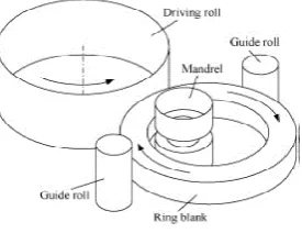
The design scheme of the ring rolling process is pre-sented in Figure 1.
Figure 1 – The ring rolling process
Two rollers that rotate in the opposite direction are fed in the ring rolling material. The gap between the rollers is lower than the material thickness caused by deformation. It is caused to elongate due to reduced material thickness. Material-roller resistance induced the material to move [2]. The volume of deformation in a single pass is limited by roller friction. If the thickness varies, rollers can be slipped. Certain procedures such as shearing, flattening and punching are to be completed before the ring rolling process in order to generate the final product. Shearing is the method of removing a necessary blank from the stock. Flattening is a method of adding sufficient force to reduce the height of the original element [5]. Eventually, the punch and dies design creates a gap in the part [7]. The processing of ring rolling is given in Figure 2
3.2 Typical Ring Rolling Products
Rolled rings find application in bearings, slewing bear-ings, turbine disks and gear blanks [8]. Ring rolling ma-chines are also used in producing solid wheels and wheel disks for high-speed trains, locomotives, railway carriag-es, trams, and subway trains. More examples of the var-ied uses of ring rolling items includes bevel gear and axle drive wheels for the automotive industry, transmission manufacturing, turbine manufacturing (turbine disks for plane propulsion engines), flanges in the computer and plant construction industry, rings for tower flanges (in off-shore wind turbines) and roller bearings (cold spin-ning) [9].
Figure 2 – The process of ring rolling
3.3 Analytical description of ring rolling
Kalpak Jian and Schmidt’s flat rolling analysis is ex-tended to the process of ring rolling [9]. Process parame-ters are defined as given in Figure 3.
Figure 3 – Description of the ring rolling process
The parameters used in the analysis are di– inner di-ameter; do – outer diameter; dr – roll diameter; dm – man-drel diameter; nr – roller rotational speed; no – ring rota-tional speed; va – advance velocity of the mandrel.
The first relationship to be developed is the dependen-cy by volume preservation between cross-sectional thick-ness and diameter. The plain strain is presumed in this situation, therefore there is no strain in the width direc-tion.
The main geometric dependencies are based on the fol-lowing requirement of the constant volume:
π(do2 – di2)w/4 = π(d 2o,0 – d 2i,0)w/4;
E 38 MECHANICAL ENGINEERING: Computational Mechanics A result for the forming roll which undergoes
convex-convex contact is given by
dr,eq = dr/[1 + 2dr/(do,0 + do)]. (2) Therefore, the corresponding flat rolling size is less than the true diameter of the greater convex-convex touch roll. Similarly, the diameter of a mandrel is given by
dm,eq = dm/[1 – 2dm/(di,0 + di)]. (3) The conversion of the convex-concave touch of the mandrel to the inner ring surface leads the corresponding flat roll size to increase than convex-flat contact for plain rolling. Now that the rolling phase of the circle has been converted into flat rolling, the draft issue needs to be addressed [10]. The draft is defined as the reduction of rolling height. The initial and final heights were inde-pendent of the rolling system itself for flat rolling. In-ring rolling, though, the heights of entry and exit are com-bined as the height of exit in one rotation becomes the height of entry for the next rotation. This coupling effect can be given in terms of the advance mandrel speed and the system's rotational speed [11]. When we consider the advanced instantaneous velocity va = dh/dt, and if the velocity of the mandrel is unchanged, the height shift in a single revolution can be interpreted as a finite difference va = (h1 – h2)/tr, the period for a single rotation is deter-mined from the ring and roll size and rotational velocity: tr = 60/no,1 = 60πd/ν1 ≈ 60πd/nr = 60d0/(drnr).
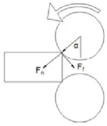
Therefore, the height change can be described as h1 – h2 = 60d0va/(drnr). (4) The h1 and h2 reflect the heights inside and outside the rolling area and the stress applied to the ring segment is proportional to the original sectional size, as there is no rotational annealing process. When we consider the peak draft state as the point of equilibrium of frictional and natural forces in the direction of rolling, a total approval angle for flat rolling can be given [12]. This condition is shown in Figure 4, where Fn describes the normal force against the piece of work and Ff the tangential frictional force to the move.
Figure 4 – Force balancing at critical rolling height
The following force component constraint must be considered in order to pull the material into the process:
Ff cosα > Fn sinα;
Ff = µFn > Fn tgα; (5) µ > tgα.
If we assume that the rolling radius exceeds the change in height (large rolling assumption),
tgα ≈ sinα ≈ (Δh/R)1/2; Δh
max = µ2R. (6)
This analysis is summarized in [4]. Setting these max-imum drafts in the following relationship
Δhmax = µ2dr/2 = 60d0vamax/(drnr);
vamax = µ2dr2nr/(120d0). (7) Therefore, to maintain the rotation of the ring during rolling, an upper limit is established on the prescribed mandrel advance velocity [2].
3.4 Numerical simulation
Figure 6 describes the modeling of ring rolling that in-cludes workpiece, mandrel, and roller guide. Modeling is done using solids works and the mesh analysis is done in ANSYS. Wire modeling and meshing of ring rolling are given in Figure 5. The mesh domain is created for quality analysis.
Finite Element Analysis (FEA) is performed using the FEA software package called ANSYS. The computer package introduces and solves the formulas that control the action of elements. The material used for the process is Aluminum 6061 alloy [12]. The material properties are provided in Table 1.
The pressure of the roller against the workpiece could be either increased or decreased, based on the desired shape of the workpiece [8].
The roller moves around the workpiece that is fixed at the stationary state. The rotational speed of the roller is 40 rad/sec to get the desired dimensional output of the workpiece.
Journal of Engineering Sciences, Volume 6, Issue 2 (2019), pp. E 36–E 40 E 39 Table 1 – Properties of Aluminum 6061 alloy
Density, kg/m3 2700
Brinell’s hardness 95
Rockwell hardness 40
Tangent modulus, MPa 1330
Ultimate tensile strength, MPa 310 Tensile yield strength, MPa 276 Young’s modulus, MPa 68.9 Ultimate bearing strength, MPa 607 Bearing yield strength, MPa 386
Poisson’s ratio 0.33
Fatigue strength, MPa 96.5
Shear modulus, MPa 26
Shear strength, MPa 207
Specific heat capacity, J/(kg·K) 896 Thermal conductivity, W/(m·K) 167 Elongation at break, % 12
4
Results
Rotational velocity is directly proportional to the time, which means that when the velocity is increasing the time taken for the process increases linearly. In this case, the rotational acceleration is equal to 50 rad/s2.
From Figure 6 a, it can be observed that the maximum and minimum static structural deformations for the pro-cess are 5.96 nm. Figure 6 b describes the maximum static structural equivalent stresses equal to 0.027 MPa.
Figure 7 a, b describes that deformations and stress in-crease with an inin-crease in time. It can be observed from Figure 8 that the maximum static structural normal stress for the process is equal to 19.8 kPa.
a
b
Figure 6 – Total deformations (a) and von Mises equivalent stresses (b)
a
b
Figure 7 – The maximum values of deformations (a) and equivalent stresses (b) in time
Figure 8 – Normal stresses
5
Conclusions
E 40 MECHANICAL ENGINEERING: Computational Mechanics
References
1. Banerjee, P., Huir, N. B. (2019). Finite element modeling of ring rolling process. Materials Today: Proceedings, Vol. 11, pp. 843–848.
2. Yang, H., Guo, L., Zhan, M., Sun, Z. (2006). Research on the influence of material properties on cold ring rolling processes by 3D-FE numerical simulation. Journal of Materials Processing Technology, Vol. 177, pp. 634–638.
3. Allegri, G., Giorleo, L., Ceretti, E., Giardini, C. (2017). Driver roll speed influence in ring rolling process. Procedia Engineer-ing, Vol. 207, pp. 1230–1235.
4. Guilleaume, C. and Brosius, A., 2019. Simulation methods for skew rolling. Procedia Manufacturing, 27, pp.1-6.
5. Dandagwhal, R. D., Kalyankar, V. D. (2019). Design optimization of rolling element bearings using advanced optimization technique. Arabian Journal for Science and Engineering, pp. 1–16.
6. Tripathi, A., Medhavi, A. (2014). Finite element simulation of hot rolling for an aluminum 2024 plate. International Journal of Scientific and Research Publications, Vol. 4(12), pp. 361–365.
7. Allegri, G., Giorleo, L., Ceretti, E. (2019). Roll gap per rotation optimization in a radial ring rolling process. AIP Conference Proceedings, Vol. 2113(1), article number 040008.
8. Hua, L., Deng, J., Qian, D. (2017). Recent development of ring rolling theory and technique. International Journal of Materi-als and Product Technology, Vol. 54(1-3), pp. 65–87.
9. Quagliato, L., Berti, G. A. (2016). Mathematical definition of the 3D strain field of the ring in the radial-axial ring rolling pro-cess. International Journal of Mechanical Sciences, Vol. 115, pp. 746–759.
10.Sun, B., Xu, J., Xing, C. (2019). Numerical and experimental investigations on the effect of mandrel feeding speed for high-speed rail bearing inner ring. The International Journal of Advanced Manufacturing Technology, Vol. 100(5-8), pp. 1993–2006. 11.Meng, W., Zhao, G. Q. (2014). Effects of key simulation parameters on conical ring rolling process. Procedia Engineering,
Vol. 81, pp. 286–291.
12.Wu, Q., Wu, J., Zhang, Y. D., Gao, H. J., Hui, D. (2019). Analysis and homogenization of residual stress in aerospace ring rolling process of 2219 aluminum alloy using thermal stress relief method. International Journal of Mechanical Sciences, Vol. 157, pp. 111–118.
13.Wasa, N., Fukui, T. (2019). Ring Rolling Mill and Method for Manufacturing Ring Rolled Material. U.S. Patent Application 10/286,443.
14.Yagami, T., Teramae, T., Fujita, E., Nagao, S., Mukouse, R., Iwasa, N., Fukui, T., Aoki, C. (2018). Material for Ring Rolling. U.S. Patent 10,094,238.
УДК 624.014
Моделювання та оптимізаційний розрахунок процесу прокатування
кілець з конструкційної сталі сталі та алюмінієвого сплаву
Тея П. С., Кумар М. Д., Крішна Р., Срінівасан М. Інститут технологій та наук ім. Пейс, 523 272, м. Онголе, Індія
Анотація. Поточні дослідження проводилися за допомогою програмного комплексу ANSYS для оптимі-зації параметрів процесу прокатування кілець. Для оптиміоптимі-зації процесу прокатування були оцінені такі пара-метри, як швидкість, осьова подача ролика і параметри приводних роликів. Як підхід до оптимізації процесу було оцінено оптимальні значення параметрів та взаємозв’язки між ними. Параметри напружено-деформованого стану оцінювались для різних швидкостей і сил, а також визначались відповідні значення критичних параметрів. Для проведення дослідження було обрано конструкційні сталі та алюмінієві сплави, оскільки саме вони використовуються для виготовлення функціональних елементів і деталей коліс. Дослі-дження проводилось шляхом зміни кутової швидкості направляючого ролика у діапазоні від 40 до 45 рад/с і зміни кутової швидкості деталі у діапазоні від 200 до 250 рад/с. Крім цього, втомна міцність робочих частин пристрою визначалася на основі аналізу кількості циклів навантаження до відмови. Також було проаналізо-вано напруження і пластичні деформації.