Effect of Using Nano Encapsulated Phase Change
Material on Thermal Performance of Micro Heat Sink
S. Sabbaghi
*and S. Mehravar
Faculty of Advanced Technologies, Dep. of Nano Chemical Eng., Shiraz University, Shiraz, I.R.Iran (*) Corresponding author:
[email protected]
(Received: 07 June 2014 and Accepted: 18 Jan. 2015)
Abstract:
The aim of this paper is to enhance thermal performance of a microchannel heat sink by using nano-encapsulated phase change material (NEPCM) slurry as a cooling fluid instead of pure fluid. A three-dimensional model of a circular channel using water slurry of NEPCM was developed. The results show a significant reduction in the mean fluid temperature along the channel and heat sink wall temperature under certain conditions for heat flux rates that depend on the NEPCM-slurry volume fraction and slurry inlet velocity. Lower temperatures across the electronic device can be attained at high heat flux compared with using water as the only cooling fluid.
Keywords: Heat sink, Latent heat, NEPCM-slurry, Phase change material.
1. INTRODUCTION
One of the effective approaches of advanced energy technologies to preserve available energy and improve its applications is the use of a latent heat storage system utilizing heat storage material or phase change materials (PCMs). The heat storage materials have the ability to alter the status with the small temperature range. The energy can be absorbed or released when the materials temperatures overpass the phase change temperature during melting and solidifying processes respectively [1-4]. It is necessary for the latent heat energy storage to have a PCM with high thermal conductivity because the rate of energy release and storage of the PCM can be hindered with low thermal conductivity. Progresses in nanotechnology field have resulted in developments of new methods for improving thermal conductivity of PCMs including dispersing high thermal conductive nanoparticles in PCM [5, 6] and nano-encapsulating PCM. Therefore, heat
Sabbaghi and Mehravar
been improved. In some of these works, the micro-encapsulated phase change material (MEPCM-slurry) was used as the cooling fluid. In the present study, the melting performance of a PCM in NEPCM-slurry in the circular micro-heat sink is studied three dimensionally.
2. METHODS
2.1 Microchannel Heat Sink
A common approach for cooling computer chips with high performance is to join the chip to a circular microchannal heat sink. During operation, a chip generates a uniform heat flux at its interface with heat sink, while a fluid coolant (NEPCM slurry) is flown through the channels. A chip and a heat sink are considered each 10×5.1 mm on a side as show in Figure 1. Heat sink meshed shows in Figure 2. The fluid is supplied in the inlet temperature, heat flux and inlet velocity equals to 298 k, 1W and 2m/s respectively.
Figure 1. a) Geometry of the microchannel heat sink, b) The heat sink front view, c) heat sink modeled
Figure 2. Heat sink meshed
Following assumptions are made:
a) The flow is laminar, steady state and incompressible with negligible viscous dissipation.
b) NEPCM-slurry thermophysical properties are temperature dependent. c) The heat sink is made of aluminum with
constant properties.
d) The external walls of channels are thermally insulated.
e) All of the chip power dissipation is transferred to the coolant, with a uniform surface heat flux although radiation heat transfer is ignored.
f) Gravitational and external body forces are not considered.
The Governing Equations
Continuity
0
)
.(
U
(1)
wk
vj
ui
U
(2) Momentum
F U T
U U p
U
U
] ) . ( 3 2 ) ) ( ( .[
)
.
(
(3)
Energy
q
T
k
T
U
c
p.
.(
)
(4)
where F is external body forces (F=0) and q is the volumetric heat source.
The latent heat of the slurry content is considered as a function of the PCM latent heat (L), liquid fraction (β) and NEPCM mass fraction (ø).
L
H
(5)
The liquid fraction is defined as the mass ratio of melted PCM to the total mass of PCM in the fluid. The PCM melting range is from Tsolidus to Tliquidus. Therefore β is described by
Equation (6).
solidus
0
if
T
T
liquidus
1
if
T
T
liquidus solidus
solidus liquidus
solidus
if
T
T
T
T
T
T
T
(6) The heat capacity of slurry is estimated by
.
2.1.1.
International Journal of Nanoscience and Nanotechnology Equation (7).
H
dT
c
c
TT
ref
f p
p
(7) Equation 8 measures the energy equation in the solid material.
0
)
.(
s
s
k
T
(8)
Numerical Method
The governing equations including continuity, energy and momentum are basic equations. Therefore, they are used to solve the heat transfer and the fluid motion. For discretizing the basic equations COMSOL multiphysics software with the finite element method (FEM) is used. In addition, SIMPLE
algorithm is used to couple the pressure and velocity fields and iterative solver is used to solve nonlinear equations. Thus, successive over-under relaxation method is used.
2.2. NEPCM-slurry
In the present study, NEPCM-slurry is analyzed mathematically with the octadecane core and styrene shell whose proportion equals to 2 and the PCM diameter equals to 167 nm according to [10]. The thermophysical properties of water, octadecane and styrene are shown in Table 1. The NEPCM water slurry is analyzed with volume fraction of 5, 10, 15 and 20% and the PCM latent heat equals to 244
J/g. Equations 9-11 define the specific heat, thermal conductivity and density of nanocapsules [7]. np sh c sh c p p
p (3 7 )
) 3 7
( c sh
np
c c
c (9) c np sh c np c c np np
1
1
d
d
k
d
d
d
k
d
k
(10) c 3 np c np
10
7
(
)
d
d
(11)
Equations 12-15 define the viscosity [7], thermal conductivity [13], density and specific heat [14] of NEPCM-slurry.
5 . 2 2 w
f
(
1
c
1
.
16
c
)
(12)
)
1
(
2
)
(
2
2
w np w np w np np w f
k
k
c
k
k
k
k
c
k
k
k
(13)
w np
f
(
1
)
c
c
(14)
w np
f p p
p c (1 )c
c
(15)
) ( np w w pnp
c c(16)
where
is the mass fraction of NEPCM.3. RESULT AND DISCUSSION
To check the correctness of present numerical model, confirmation is made by comparing the
Table 1. The thermophysical properties of NEPCM-slurry [11, 12].
Octadecane Polystyrene Water
Density
(kg/ m3) 1050 838.466+1.40T-0.003T
2+3.71810-7T3
Specific heat
(J/ kg.K) 2100 1270 12010.147-80.407T+0.3T
2-5.38 10-4T3
Thermal conductivity
(W /m.K)
0.358 if
T
T
solidus 0.148 if T Tliquidus0.033 -0.869+0.009T-1.584 10-5T2+7.975
10-9T3
Viscosity
(Pa.s) - - 1.38-0.021T+1.360
10-4T2-4.645 10-7
T3 liquidus
T 302 - -
solidus
T
299 - -2.1.2.
Sabbaghi and Mehravar
present numerical results with the available literature data. The model geometry presented is a rectangular microchannel heat sink [9]. The heat sink
solid material is aluminum
.The thermal boundary condition is a constant heat flux of 100 W/cm2 performing at the bottom
wall of heat sink. The inlet velocity is 1 m/s and the inlet temperature equals to 300 K and the melting range of 300-305 K is used for PCM. Figure 3 compares the mean flow temperature for PCM slurry with volume fraction of 15% and the same condition used in the mentioned study. The figure illustrates that the agreement between results of present model and the mentioned is acceptable.
Figure 3.Comparison of present model to the result reported in [9].
3.1. Mean Flow Temperature
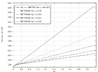
The mean flow temperature along the channel for 0% (pure water), 5, 10, 15 and 20% volume fraction of NEPCM are shown in Figure 4. As the results show with increasing volume fraction of NEPCM the mean fluid temperature is reduced. Also, for all volume fractions of NEPCM the mean flow temperature rises nonlinearly at the entrance of channel and continues linearly to the channel exit. Using slurry in a higher volume fraction results in lower fluid temperature due to higher latent heat of PCM ratio. It should be noted that the slurry flow is considered to be Newtonian provided that the volume fraction of the NEPCM particle is less than 25% [15] that is why the slurry with volume fraction of 20% is used in the present research. Equation 17 describes the mean flow temperature.
c c
A p c
A p c
m
dA
vc
TdA
vc
T
(17)
Figure 4. Mean flow temperature in different volume fraction of NEPCM-slurry Vin= 2 m/s, q"= 1 W.
3.2. Thermal Conductivity
Equation 18 calculates the thermal conductivity enhancement factor (
k
r).c c f r
k
k
k
k
(18) where kf and kc are thermal conductivity of
NEPCM-slurry and PCM respectively. Figure 5 shows the kr for NEPCM-slurry volume fraction of
20% versus channel length. As shown in the result there is the improvement of NEPCM-slurry thermal conductivity in comparison to the thermal conductivity of PCM. Therefore, nano-encapculating PCM is a method to enhance their thermal conductivity. The modification percentage of thermal conductivity resulted from NEPCM-slurry as a cooling fluid in contrast with PCM for volume fraction of 20% is 30%.
3.3. Inlet Velocity (V
in)
Figure 6 shows the temperature of
NEPCM-slurry at 20% versus the channel in various
inlet velocities. Since Reynolds number
changes with volume fraction of
NEPCM-slurry as a result of alteration in NEPCM-slurry
viscosity, instead of Reynolds number the inlet
velocity is investigated. According to the
results, fluid temperature rise decreases with
increasing the inlet velocity. Latent heat and
thermal conductivity of PCM are more
effective at high velocity.
International Journal of Nanoscience and Nanotechnology
Figure 5. Thermal conductivity enhancement factor, c=20%, Vin= 2 m/s, q"= 1 W.
Figure 6. Mean flow temperature in different inlet velocities for c= 20%, q"=1 W.
3.4. Heat Flux (q
'')
The effect of increasing heat flux with different values of 1, 2, 3, 4 and 5W on the mean flow temperature (NEPCM-slurry with volume fraction of 20%) is shown in Figure 7. The results show that the increase in heat flux leads to the increase of the temperature. By comparing these results it can be seen that the heat sink has a weak thermal performance in heat flux of 5W. Nevertheless, it has approximately the same temperature rise in contrast with using water in heat flux higher than 5W. Figure 4 illustrates it. It shows pure water temperature in heat flux of 1W is 363K and according to Figure 7 the temperature of NEPCM-slurry with volume fraction of 20% is about 362 K in heat flux of 5W.
Figure 7. Mean flow temperature in different heat fluxes for c=20%, Vin=2 m/s, q"=1 W.
3.5. Wall Material
The influence of solid materials (Cu, Al and Steel AISI 4340) on the temperature of the heat sink of top wall with slurry volume fraction of 20% is shown in Figure 8. Referring to the results, utilizing materials with higher thermal conductivity will reduce the wall temperature. Furthermore, the heat conduction of the channel walls is affected by these materials and subsequently the PCM melting process along the microchannel is influenced (material properties are shown in Table 2).
Figure 8.Effect of heat sink material on wall temperature for c= 20%, Vin=2 m/s, q"=1 W.
Table 2. The physical properties of solid material [16].
Al Cu Steel AISI
4340
Density(kg/m) 2700 8700 7850 Specific heat (J/kg.K) 904 385 475 Thermal conductivity
(W/m.K) 237 400 44.5
Sabbaghi and Mehravar
4. CONCLUSIONS
- In order to do thermal management for an electronic device with high heat dissipation, the high heat flux ability of microchannels is joined with the large latent heat of PCM to attain high heat flux with little temperature alteration. - Using NEPCM-slurry instead of pure water
decreases the heat sink temperature, and with increasing the slurry volume fraction lower temperature rise is observed.
- PCM thermal conductivity is enhanced around 30% by using nano-encapsulation of PCM with volume fraction of 20%. Thus, modifying thermal conductivity is one of the most important reasons for choosing this fluid. - Increasing the slurry inlet velocity and decreasing
heat flux cause reduction of fluid temperature rise. In comparison to pure water for the same temperature of the heat sink the slurry can be used in higher heat flux and lower inlet velocity. - The wall temperature will be reduced
significantly by using higher conductive metals such as Cu.
NOMENCLATURE
Ac Channel cross-sectional area (m2) c NEPCM volume fractio
cp specific heat capacity (J/ kg K) dc PCM particle diameter (m) dnp nanoparticle (polymer and PCM)
diameter (m)
k thermal conductivity (W/m K) L NEPCM latent heat (J/ kg) p Pressure (Pa)
q’’ heat flux at the channel walls (W) Tliquidus end temperature of NEPCM
melting (K)
T mean flow temperature (K) Ts heat sink solid temperature (K) Tsolidus start temperature of NEPCM
melting (K) V Velocity
u fluid x-component velocity (m/s) v fluid y-component velocity (m/s) w fluid z-component velocity (m/s)
ρ GREEK LETTERS
density (kg/m3)
µ dynamic viscosity (kg/m s)
c SUBSCRIPTS
PCM
f Fluid
sh Polymer
np nanoparticle (polymer and PCM)
w Water
in Inl
s heat sink solid
REFERENCE
1. G. Sun and Z. Zhang: Int. J. Pharmaceutics., Vol. 242, (2002), pp. 307-311.
2. S. Mondal: Applied Therm. Eng., Vol. 28, No. 11-12, (2008), pp. 1536-1550.
3. N. Zhu, Z. Ma and S. Wang: Energy Convers Manage., Vol. 50, No. 12, (2009), pp. 3169-3181. 4. M. Kenisarin and K. Mahkamov: Renewable and
Sus-tainable Energy Reviews., Vol. 11, No. 9, (2007), pp. 1913- 1965.
5. J. Fan and L. Q. Wang: J. Heat Trans., Vol. 133, No. 4, (2011).
6. L. Godson, B. Raja, D.M. Lal, and S. Wongwises: Sustain. Energy Rev., Vol. 14, No. 2, (2010), pp. 629.
7. M. Goel, S.K. Roy and S. Sengupta: Heat and Mass Trans., Vol. 37, No. 4, (1994), pp. 593 - 604. 8. S. Kondle, J.L. Alvarado and C. Marsh: J. Heat
Trans., Vol. 135, (2013), p. 052801-1.
9. R. Sabbah, M.M. Farid and S. Al-Hallaj: Applied Therm. Eng., Vol. 29, (2008), pp 445–454.
10.Z. Dong and L. Shuo: School of materials sci. and eng., Tongji University, Siping Road 1239, Shanghai, 200092, China (2010).
11.B.S. Hemingway and R.A. Robie: U.S. Geological Survey., J. USGS Open-file Report 94-671. (1994). 12.B. Zalba, J.M. Marın, L.F. Cabeza and H. Mehling: Applied Therm. Eng., Vol. 23, (2003), p. 251–283. 13.J.C. Maxwell: A Treatise on Electricity and
Magnetism, Oxford University, (1881), in Press. 14.J. Lee and I. Mudawar: Int. J. Heat and Mass Trans.,
Vol. 50, (2007), pp. 452–463.
15.P. Charunyakorn, S. Sengupta and S.K. Roy: Int. J. Heat and Mass Trans., Vol. 34 No. 3, (1991), pp. 819–833.
16.Library of COMSOL Multiphysics 4.3a.

![Table 1. The thermophysical properties of NEPCM-slurry [11, 12]. Octadecane Polystyrene Water](https://thumb-us.123doks.com/thumbv2/123dok_us/1313814.1639090/3.595.67.526.564.743/table-thermophysical-properties-nepcm-slurry-octadecane-polystyrene-water.webp)