A Coloured Petri Net Methodology and Library
for Security Analysis of Network Protocols
San Choosang and Steven Gordon
Sirindhorn International Institute of TechnologyThammasat University Bangkadi, Thailand 12000
Email: [email protected], [email protected]
Abstract—Formal methods are often used to prove prop-erties of network protocols, including required security properties. However for a protocol modeller the techniques available for security analysis often require expert knowl-edge of the technique. Also the tight coupling of protocol model and security attacks limit re-use of models. With Coloured Petri nets as the selected formal method, this paper proposes a methodology to support a modeller in performing security analysis of a protocol. The methodology enhances the re-usability, extendability and readability of protocol and attack models, with the aim of simplifying the tasks of the modeller. Key to the methodology is the decoupling of the protocol and attack models by using the hierarchical structure of Coloured Petri nets. Also a library of attack modules is developed based on Dolev-Yao assumptions; the modules can be composed to create complex attacks and re-used across different protocols. To demonstrate the methodology, a case study analysing the ZigBee RF4CE pairing protocol is presented. The case study shows the ease at which attacks can be integrated and how the methodology addresses the state space explosion problem. The impact of two attacks on the ZigBee protocol are analysed, showing several scenarios which lead to a mismatch in state at the ZigBee devices.
Index Terms—security analysis, formal methods, commu-nication protocols, ZigBee RF4CE, Coloured Petri nets
I. INTRODUCTION
There has been a rapid growth in the development of communication protocols to improve the capability and the performance of networking technology. Significant effort is directed to the design of new network protocols by researchers, companies and standard development or-ganisations. Their primary focus is on performance, anal-ysed using mathematical and simulation models. However security of protocols is also important.
There is a wide body of research addressing security analysis of protocols [2]. The majority of this research concentrates on building a model of a protocol and proving security properties in a mathematical formalism. Although able to produce proofs of security properties, the two main limitations of these approach are:
• Difficult for protocol modellers to use: the tech-niques require detailed knowledge of the mathemat-ical methods to create a model.
Manuscript received April 4, 2012; revised June 13, 2013; accepted July 8, 2013.
This work was supported by the National Research University Project of Thailand, Office of Higher Education Commission.
• Lack of integration with other design steps: the security method cannot be (even partially) re-used for performance analysis, and is normally not in a form to be used in a standard document.
To address these issues, one alternative is to use for-mal models that offer graphical notations for modelling protocols, thereby making it easier for protocol modellers to analysis security properties without being experts in the underlying mathematics. Coloured Petri nets (CPNs) [1] are one such formal method. Recently researchers have been applying CPNs to analyse the security of network protocols [3], [4], [10], [15], [16], [17], [18]. Our research presents a new methodology that combines ideas from recent research, as well as introduces new con-cepts to prove security properties of network protocols. Our proposed methodology separates the model of the protocol from models of security attacks. We have also developed a library of attack modules that can be re-used in different protocols. We present the steps that a modeller uses to incorporate attack modules from the library into their protocol model. We also include mechanisms that can help alleviate the state space explosion problem. A significant difference between our methodology and other approaches (e.g. [3], [17]) is that we require the modeller to analyse attacks in an iterative manner. That is, our approach encourages the modeller to analyse a single attack at a time, where as [3] and [17] have the advantage in that they allow analysis of multiple different attacks, potentially detecting unknown attacks. We believe the extra effort required by the modeller to analyse single attacks at a time is a reasonably trade-off for the benefits of re-usable, extendable and readable models. We demonstrate our methodology with a small but relevant case study that analyses multiple attacks on the ZigBee RF4CE wireless networking protocol [5].
Section VII, respectively. We close with conclusion and future work in Section VIII.
II. BACKGROUND
A. Formal Modelling of Protocols
Formal methods can be used for the specification and analysis of communication protocols to provide insights into the system behaviour, early detection of errors in the design process, remove ambiguities from specifications and to prove correctness of the protocols [6]. Protocol verification is one common use of formal methods, where proofs are made that a protocol satisfies a set of require-ments or desired properties (e.g. faithful refinement of a service, absence of deadlocks). Although not as common, formal methods can also be used to analyse the perfor-mance and security of properties. It is more common that performance analysis is undertaken with purpose-built network simulators (e.g. OPNET, ns2), while various mathematical techniques are used for security analysis. Seldom is a single formal method used for the analysis of functional, performance and security properties of a protocol, making it difficult for a protocol modeller to gain the expertise to perform all types of analysis.
Coloured Petri nets [1] are one formal method which have the potential of supporting functional, performance and security analysis of protocols. CPNs are well suited to modelling protocols as they support concurrency and non-determinism, and allow for modelling at different levels of abstraction, such as a service and a protocol. Importantly they have a graphical notation, simplifying the development and validation of protocol models and have strong computer tool support, CPN Tools [7]. There are many case studies applying CPNs to protocol veri-fication [8], [9], [10], [11], as well as for performance analysis [12], [13], [14] and security analysis [4], [3]. Ideally a protocol modeller could create a single CPN model of a protocol, from which they can automatically prove functional and security properties of the protocol and conduct a performance evaluation. One challenge in achieving this is simplifying the effort needed by the protocol modeller in incorporating security attacks into an existing protocol model.
A common approach for security analysis of protocols is to create a model of the protocol and then modify that model to incorporate selected attacks. Using a formal method such as CPNs to create the model then allows analysis of the impact of attacks on the protocol, e.g. using model checking or state space analysis. Incorporating an attack into an existing model commonly involves modifying the structure of the existing model [10], [15], [16]. However this often makes the protocol model and attack tightly coupled, limiting the chances of re-using or extending the models and sometimes reduces readability of the model. The focus of this paper is decoupling the model of the protocol from the attack, so that a mod-eller can perform security analysis while enhancing the readability, re-usability and extendability of their models.
B. Coloured Petri Nets
CPNs are a directed graph with two types of nodes: a set of places,P, and a set of transitions,T, represented by ellipses and rectangles, respectively. Places and transitions are connected by directed arcs: input arcs (place to transition) and output arcs (transition to place). Places are typed by a colour set and the values that marks on the places are calledtokens. Transitions and arcs can also have inscriptions (expressions) to control the execution of the model. The execution of a CPN consists of occurrence of transitions. A transition can occur if and only if: for all input places, sufficient tokens exist that satisfy the input arc inscriptions, and the transition inscription evaluates to true.
The formal definition of non-hierarchical CPNs follows [1]. (Hierarchical CPNs, which are used in this paper, extend this definition; in Section IV-C we will show the extended definition for our models).
Definition 1. A non-hierarchical Coloured Petri Net is a
nine-tupleCPN = (P, T, A,Σ, V, C, G, E, I), where:
1) P is a finite set ofplaces.
2) Tis a finite set oftransitionsT such thatP∩T =∅.
3) A⊆P×T∪T×P is a set of directed arcs.
4) Σis a finite set of non-emptycolour sets.
5) V is a finite set of typed variables such that
T ype[v]∈Σfor all variables ∀v∈V.
6) C:P →Σis acolour set functionthat assigns a
colour set to each place.
7) G:T →EXP RV is aguard functionthat assigns
a guard to each transitiontsuch thatT ype[G(t)] =
Boolean.
8) E :A→EXP RV is anarc expression function
that assigns an arc expression to each arc a such
that T ype[E(a)] =C(p)M S, where pis the place
connected to the arca.
9) I:P →EXP R∅ is aninitialisation functionthat
assigns an initialisation expression to each placep
such thatT ype[I(p)] =C(p)M S.
For the inscriptions (C, G, E, I) EXP R denotes the set of expressions provided by the inscription language CPN ML (an extension of Standard ML). The type of an expression e is denoted by T ype[e].M S refers to a multiset. Graphically, in this paper places are illustrated as eclipses, transitions as rectangles, guards in square brackets, and all other inscriptions located next to the corresponding place/arc.
III. RELATEDWORK
Xu and Xie [16] present a methodology for modelling attacks in security protocols using CPNs, and apply it to the Andrew Secure RPC protocol. The methodol-ogy recommends separating the models of the attacks from the original protocol model. However no details are given as to how to do this for a specific set of attacks. The modelling constructs and declarations to be used are not presented by the authors. Xu and Xie demonstrate the modelling of an attack on the Andrew Secure RPC protocol. Using state space analysis they show that the introduction of an attack in the protocol exposes a weakness (which is well known for Andrew Secure RPC). However this can be considered a ’toy-example’ in terms of complexity. Many protocols will be much more complex, and hence the state explosion problem will arise. Xu and Xie give no techniques for alleviating the state explosion problem.
Our research extends upon the work by Xu and Xie. In a similar manner we keep the models of attacks independent from the original protocol model. Further-more, we also provide a library of models of different attacks and design the methods for incorporating into different protocols. In addition, we present techniques for alleviating the state explosion problem when multiple attacks are allowed (a case not considered by Xu and Xie). Suriadi et al. [10] has applied CPNs to model privacy enhancing protocols, in particular PIEMCP. They present the concept of abstracting from the cryptographic opera-tions (i.e. not implementing the encryption ciphers) so the modelling can focus on the protocol exchange. To handle multiple types of attacks in one model they introduce conditional statements on selected arc inscriptions in the CPNs. Temporal logic is applied on the state space to prove security properties. While providing detailed analysis of PIEMCP, the approach used by Suriadi et al. is not directly applicable to other protocols. In particular, they only model attacks from insiders (nodes participaing in the protocol that behave maliciously), but not from outsiders. Numerous attacks on protocols involve out-siders (in many cases, inout-siders are assumed to be trusted). The approach of modelling attacks as conditions on arc inscriptions means the attack models cannot be easily applied to different protocols.
Our research provides a different and more generic methodology for modelling attacks than that proposed by Suriadi et al., focussing on attacks by external nodes, not insiders.
Al-Azzoni et al. [3] presents one of the first method-ologies for verifying cryptographic protocols with CPNs. Starting with an existing model of a protocol with no intruder, they add a substitution transition on the top-level page to represent the intruder. Changes to the model include new declarations and an intruder page that models the attacks on communication channels of the normal entities in the protocol. The attacker model allows for interception, modification and insertion of messages. To reduce the state space, they introduce new places to the existing entities so that unnecessary interleaving
between subprocesses of the entities are restricted. The methodology is demonstrated for the TMN authenticated key exchange protocol.
Permpoontanalarp and Changkhanal [17], [18] have developed a modelling methodology that extends the work of Al-Azzoni et al. [3] and is similar to Xu and Xie, modelling the attacker as a independent entity between initiator and responder in a protocol. The methodology includes an approach for defining vulnerability events, as well as obtaining a trace of events that lead to a discovered attack. The methodology has been applied to two examples: TMN authenticated key exchange and Micali’s contract signing protocol.
The works of both Al-Azzoni et al. and Permpoon-tanalarp and Changkhanal are similar in how attackers are introduced. Our research extends upon their approach, using a similar methodology. However a key difference is the detail in which attacks are modelled. Their work present models of attacks on specific protocols, namely TMN. Their attack models are general, in that they allow the attacker to intercept and modify any message. This has the advantage that the resulting state space can be used to identify different possible successful attacks, including unknown attacks. The disadvantage is that the state space size may increase rapidly.
To overcome the state space explosion, our methodol-ogy allows the modeller to limit the types of messages that can be intercepted, modified and inserted. But this comes at the expense of more specific attack models, i.e. the analysis identifies a only restricted set of possible successful attacks. In order to overcome this limitation, a modeller must model and analyse specific attacks sepa-rately. Although extra effort is therefore required by the modeller, we believe this will fit with the incremental approach modellers often use, especially when supported by the library of attack modules provided.
IV. SECURITYANALYSISMETHODOLOGY
A. Methodology Overview
We propose a methodology for modelling and analysing network protocols from a functional and security view-point using Coloured Petri nets. The methodology sets out the steps that a modeller should follow, defines specific parts of the CPN protocol model and offers a library of common attacks. The main steps are:
1) Create an original protocol model: The model of the protocol must be created following the protocol modelling approach described in Section IV-B. 2) Functional analysis of the protocols: analyse the
protocol model to investigate unexpected be-haviours of the protocol by using state space anal-ysis.
3) Attack integration: add the attack modules into the communication channels of the original protocol model.
The steps are designed with three primary features in mind: re-usability, extendability and readability. Note that the last two steps will in practice be performed iteratively using different attacks, i.e. one attack model per computation of the state space. For example, a sim-ple, known attack may be modelled and analysed first. Once completed, a more complex attack is modelled and analysed, and so on until the modeller is confident of the protocol strengths.
Developing a CPN model of a communications pro-tocol requires significant time and effort. Typically CPN models are created to support functional analysis of the protocol, although performance analysis is also possible. Our methodology requires the modeller to use defined constructs for modelling the communication channel in CPNs. Although this limits the modeller, the constructs are sufficient to cover most common scenarios (e.g. or-dered or unoror-dered channels, lossy or lossless channels). And importantly by using the defined constructs the mod-eller can re-use the functional protocol model for security analysis with few changes. Re-using the same protocol model is a significant benefit of our methodology as the modeller avoids challenges of managing two separate models.
A key idea in our methodology is that the protocol model should support analysis of multiple attacks. We implement attacks using common attack modules that can be composed to form more specific and complex attacks. The attack modules are not specific to a protocol and therefore are re-usable across different protocols. With our methodology a modeller can concentrate on the protocol modelling, re-using the library of attack modules as needed.
The attack modules are designed so that they can be composed together in different ways to create different attacks. They can also be easily plugged in to the protocol model. This offers extendability, in that many attacks can be created using the common attack modules.
A key advantage of CPNs over other formal methods is that their graphical notation allows modellers to visualise the protocol operation. However it is still possible for a modeller to make a CPN model difficult to read (e.g. very long arc inscriptions, many crossing arcs, poorly positioned places and transitions). In designing the attack modules and separation from the protocol model in our methodology, we focussed on maintaining the readability of the CPN. Rather than modelling attacks as a set of conditional statements in inscriptions on arcs within the protocol model (e.g. [10]) we only require very minor modifications to the existing protocol model so that it maintains its readability.
These three features—re-usability, extendability and readability—are further explained when describing the individual steps in the remainder of this section. They are demonstrated in the case study on RF4CE in Section VI.
B. Functional Protocol Model
The first step of this methodology is to create a CPN model of the protocol under investigation. CPNs are often used to analyse functional behaviour of protocols (e.g. ab-sence of deadlocks, comparison to service specifications) and hence we refer to the original model as thefunctional
protocol model.
There are various ways to model a protocol with CPNs [1], [19], depending on the objectives of the protocol modeller. Although we do not require any specific ap-proach, in our methodology the modeller must model the communicating entities independently such that they only communicate via a communications channel model. This imposes some limitations on what type of protocols can be modelled. Our methodology therefore assumes the protocol under investigation uses:
• Unicast communications with only two entities in-volved. Currently multicast/broadcast and multi-party protocols (e.g. client–server–database) cannot be modelled.
• A full-duplex communications channel. This
in-cludes support for both ordered and unordered chan-nels, as well as lossy and lossless channels. The channels can represent a single link or an entire communications network.
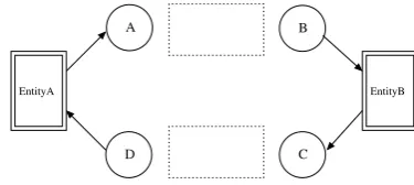
The required structure of the functional protocol model, i.e. the top-level CPN page, is shown in Fig. 1.
EntityA
A
D
B
C
EntityB
Fig. 1. General Structure of Functional Protocol Model
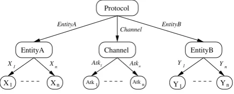
Each protocol entity is modelled by a substitution transition,EntityAandEntityB. Each substitution transition is assigned a sub-module, a CPN page that models the protocol entity in detail (e.g. packet transmission and reception, timers, processing algorithms). This structure is defined by a module hierarchywhich is a directed graph with a node for each module and a labelled arc for each substitution transition. Fig. 2 is a graphical representation of the module hierarchy for the functional protocol CPN model. The top-level module must have two sub-modules,
EntityAandEntityB. ModulesXi andYi represent a
sub-modules underEntityAandEntityBsubstitution transitions which model the detail of each protocol entity. They are not required—it is the choice of the modeller as to how to model the protocol details.
EntityA EntityB
X1 Xn Y1 Yn
X1 Xn Y1 Yn
EntityA EntityB
Protocol
Fig. 2. Module Hierarchy of Functional Protocol Model
unordered and ordered delivery channel models are shown in Fig. 3 and Fig. 4, respectively.
A frame Channel frame B
Fig. 3. Example CPN Model of Unordered Channel
A frame::queue1 Channel queue2^^[frame] B
queue1 queue2
Fig. 4. Example CPN Model of Ordered Channel
The rationale for this functional protocol model design is to support re-usability and readability of the CPN. Separating protocol entities by a communication channel in the CPN corresponds to the implementation of a protocol, i.e. entities are in a distributed system and can only communicate via the channels. In Section IV-E we will show the functional protocol model can easily be re-used for security analysis by integrating attacks in the communication channel. The detailed models of the protocol entities require few or no changes. This also maintains the readability of the CPN.
C. Formal Definition of Functional Protocol Model
A formal definition of the functional protocol model required in our methodology is given in Definitions 2, 3 and 4. These definitions are based on the definition of hierarchical CPNs in [1], which extend the non-hierarchical CPN in Definition 1. However Definitions 2, 3 and 4 impose restrictions on substitution transitions and the module hierarchy.
Definition 2. A Protocol Coloured Petri Net Module is a
four-tuple PCPNM = (CP N, Tsub, Pport, P T), where:
1) CPN = (P, T, A,Σ, V, C, G, E, I) is a
non-hierarchical Coloured Petri Net.
2) Tsub⊆T is a set ofsubstitution transitions, where:
Tsub={EntityA, EntityB}
3) Pport ⊆P is a set of port places, where:
Pport =∅
4) P T : Pport → {IN, OU T, I/O} is a port type
functionthat assigns a port type to each port place.
Definition 3. A hierarchical functional protocol Coloured
Petri Net is a four-tuple FCPNH = (S, SM, P S, F S),
where:
1) S is a finite set of modules. Each module
is a Coloured Petri Net Module s =
((Ps, Ts, As,Σs, Vs, Cs, Gs, Es, Is), Ts
sub, Pports , P Ts).
It is required that (Ps1∪Ts1)∩(Ps2∪Ts2) =∅
for all s1, s2∈S such thats16=s2, where:
S={P rotocol, EntityA, EntityB,
X1, . . . , Xn, Y1, . . . , Yn}
2) SM : Tsub → S is a submodule function
that assigns a submodule to each substitution
transition. It is required that the module hierarchy is acyclic, where:
SM:
EntityAProtocol 7→EntityA
EntityBProtocol 7→EntityB
XiEntityA 7→Xi
YiEntityB 7→Yi
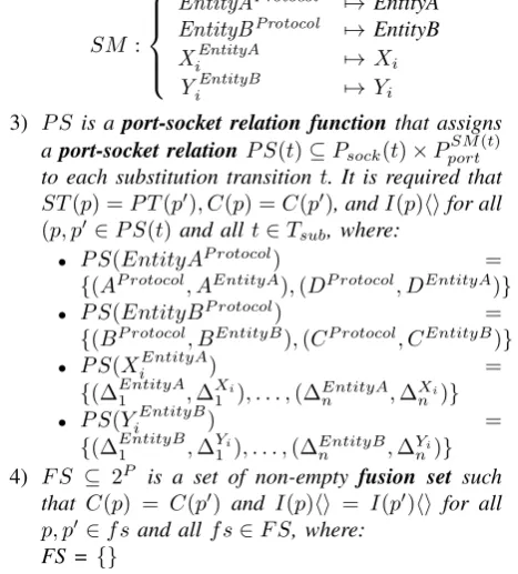
3) P S is aport-socket relation function that assigns
aport-socket relationP S(t)⊆Psock(t)×P
SM(t) port
to each substitution transition t. It is required that
ST(p) =P T(p0), C(p) =C(p0), andI(p)hifor all
(p, p0 ∈P S(t)and allt∈Tsub, where:
• P S(EntityAP rotocol) =
{(AP rotocol, AEntityA),(DP rotocol, DEntityA)}
• P S(EntityBP rotocol) =
{(BP rotocol, BEntityB),(CP rotocol, CEntityB)}
• P S(XiEntityA) =
{(∆EntityA1 ,∆Xi
1 ), . . . ,(∆EntityAn ,∆Xni)}
• P S(YiEntityB) =
{(∆EntityB1 ,∆Yi
1 ), . . . ,(∆EntityBn ,∆Yni)}
4) F S ⊆ 2P is a set of non-empty fusion set such
that C(p) = C(p0) and I(p)hi = I(p0)hi for all
p, p0∈f sand all f s∈F S, where:
FS ={}
Definition 4. The module hierarchy for a
hierar-chical functional protocol model Coloured Petri Net
F CP NH = (S, SM, P S, F S) is a directed graph
M H= (NM H, AM H), where:
1) NM H =S is the set ofnodes, where
NM H ={P rotocol, EntityA, EntityB,
X1, . . . , Xn, Y1, . . . , Yn}
2) AM H = {(s1, t, s2) ∈ NM H ×Tsub×NM H|t ∈
Ts1
sub∧s2=SM(t)}is the set of arcs, where
AM H ={
(P rotocol, EntityA, EntityA),
(EntityA, X1, X1),
. . . ,
(EntityA, Xn, Xn),
(P rotocol, EntityB, EntityB),
(EntityB, Y1, Y1),
. . . ,
(EntityB, Yn, Yn)}
D. Attack Modules Library
assumptions establish a model of what an attacker can do. According to Dolev-Yao an attacker has full control over the communication channel and can carry out the following actions:
1) Tapping and storage of all messages that pass through the communication channel.
2) Forwarding or blocking of messages. 3) Generation of forged messages.
4) Decryption of cryptographic messages if the at-tacker has a matching key.
5) The attacker can take part in the protocol, so pretending to be any entity is possible.
We use the Dolev-Yao attacker model to create a set of
attack modules: partial CPNs that model the behaviour of
common attack operations. The attack modules are:
• Interception module (Fig. 5). This module allows the attacker to intercept a frame that is begin transmitted through the communication channel. A copy of the frame is stored for future use.
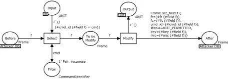
• Modification module (Fig. 6). This module allows
the attacker to change the content of the target frame.
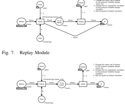
• Replay module (Fig. 7) This module allows the
attacker to re-send a frame that has previously been intercepted by the attacker.
• Injection module (Fig. 8) This module allows the attacker to create a new frame and send it to the destination entity.
• Drop module (Fig. 9) This module allows the at-tacker to discard a frame that is currently being transmitted through the communication channel.
• Message generation module (Fig. 10) This module allows the attacker to generate a new frame which will be injected to the target entity.
1. Change the colour set of places to the protocol modeller design colour set
2. Change the arc expression variables to the protocol modeller design variables
3. Edit the guard at Intercept transition ft 1`() frame frame Intercept
[#FrameType frame = ft] Attacker
DB Attacker DBFrame
Filter FrameType Output Out UNIT Input In Frame In Out Attacker DB
Fig. 5. Interception Module
1. Change the colour set of places to the protocol modeller design colour set
2. Change the arc expression variables to the protocol modeller design variables
3. Edit the guard at Select transition 4. Edit the Modification Function
Function Modification ft 1`() 1`() frame frame frame Modify Select
[#FrameType frame = ft] Output Out UNIT
After Attacker DBFrame To be Modify Frame Input In UNIT Filter FrameType Before
Attacker DBFrame Attacker DB
In
Attacker DB Out
Fig. 6. Modification Module
The attack modules have several common design fea-tures. Each attack module has an Inputplace and Output
1. Change the colour set of places to the protocol modeller design colour set
2. Change the arc expression variables to the protocol modeller design variables 3. Edit the guard at Select transition
frame 1`() 1`() ft frame frame frame frame Replay Select
[#FrameType frame = ft]
Output Out UNIT B Out Frame To be Replay Frame Filter FrameType Input In UNIT Before Attacker DBFrame Attacker DB
In
Out Out
Fig. 7. Replay Module
1. Change the colour set of places to the protocol modeller design colour set
2. Change the arc expression variables to the protocol modeller design variables 3. Edit the guard at Select transition
ft 1`() 1`() frame frame frame frame Inject Select
[#FrameType frame = ft]
Output Out UNIT B Out Frame To be Inject Frame Filter FrameType Input In UNIT Before
Attacker DBFrame Attacker DB
In
Out Out
Fig. 8. Injection Module
place. A token on the Input place enables the attack to occur while a token in the output place signifies the completion of the attack. When composing multiple modules to create more complex attacks, theOutputplace of one module is connected to theInputplace of the next module (SectionIV-E further describes how the modules are integrated).
An attack often involves manipulating frames sent between the protocol entities. The success of an attack may depend on manipulating and storing multiple frames. Therefore we use a single place to store the frames as they are received and after they are modified. The place to store the frames is the attackers database of information (the model could be extended to store information other than frames if needed). Although only one place is needed, to enhance the readability of the CPN we use a fusion place,
Attacker DB, which has two subplaces Before and After.
These two subplaces are in fact the same place: a token
inBefore also means that token exists inAfter.
1. Change the colour set of places to the protocol modeller design colour set
2. Change the arc expression variables to the protocol modeller design variables 3. Edit the guard at Select transition 1`() 1`() ft frame frame frame Drop Select
[#FrameType frame = ft]
Output Out UNIT To be Drop Frame Input In UNIT Filter FrameType Before
Attacker DBFrame Attacker DB
In Out
Fig. 9. Drop Module
1. Change the colour set of places to the protocol modeller design colour set
2. Change the arc expression variables to the protocol modeller design variables
3. Edit the guard at Generate Frame transition 4. Edit the Frame Generation Function
Function Frame Generation 1`() 1`() n-1 n Generate Frame [n>0] Limit INT Input In UNIT Output Out UNIT After
Attacker DBFrame Attacker DB Out
In
A common problem in using state space analysis in CPNs (and other formal methods) is state explosion: the number of states grow rapidly leading to exhaustion of memory or reasonable time in calculating the state space. In designing a CPN tradeoffs can be made that aim to reduce the state space size often at the expense of expressability and readability of the model. The design of the attack modules allows every frame transmitted to be processed by that module, leading to potentially a large number of new states in the security protocol model. Therefore we introduce a Filter place which the modeller uses to select the frames to be processed by the attack module. By limiting the attack module to process only a selection of all possible frames the resulting state space can be smaller. However this is at the expense of limiting the analysis to attacks on only the selected frames: analysis of the security protocol model will not cover attacks on frames not selected by the modeller. Selecting the frames to filter to minimise the state space, while reducing the chance that attacks will not be covered, currently depends on knowledge of the protocol under analysis. A possible area of future work would be to present guidelines for modellers on applying filtering to assist this model design decision.
To illustrate how theFilterplace can be used to control the state space size, consider a protocol that allows three different frame types to be sent. Without the Filterplace a replay attack would allow any of those three frames to be re-sent at any time. Although this allows for any type of replay attack but it can lead to a significant increase in state space size (compared to the functional protocol model). With knowledge of the protocol and potential attacks, the modeller may decide that only one frame type should be considered in a replay attack (assuming the other two frame types will not lead to a successful attack). The modeller would specify the frame type in
the Filter place. This will reduce the state space size,
but requires additional knowledge and assumptions about likely attacks
The modeller selects the frames that can be processed by an attack module by setting the initial marking, which is a list of frames, of theFilterplace.
Another approach to control the state space size is to limit the number of occurrences of an attack module. The
Limit place contains an integer indicating the number of
times an attack can be repeated. For example in the Mes-sage Generation module, if we do not limit the number of generated frame the CPN would allow generation of an infinite number of frames (possibly leading to infinite state space size). The modeller can use the initial marking of the Limit place to limit the number of frames generated. For example if the initial marking of the Limit place is set to three, that means three frames can be generated by this module. Again this is a design tradeoff that reduces the state space size but requires the modeller to make additional assumptions about the protocol and attack operation.
As an example of the module design, Fig. 6 shows the modification attack module. In this module there are 6 places and 2 transitions. This attack can occur when there is one token in the Inputplace. Then a frame will be selected fromBeforeplace to be modified through the
Select transition filtered by the Filterplace. After that a selected frame will be modified by the Modifytransition, stored in the After place and produce one token in the
Output place.
E. Integrating Attack Modules
After the functional protocol model is created and analysed the next step is to integrate an attack model into the functional model. Attack modules from the library are inserted into the communication channel. We refer to the functional model with integrated attack model as
the security protocol model. Fig. 11 shows the module
hierarchy of a security protocol model. Compared to the functional protocol hierarchy (Fig. 2), the communication channel and attack in each direction is now modelled by a separate substitution transition, with each sub-page con-taining further substitution transitions for attack modules. (For clarity, Fig. 11 only shows the Channel sub-module for one direction of communications; there is another for the opposite direction).
EntityB
Y1 Yn
Y
1 Yn
Atk
1 Atkn
EntityA
X1 Xn
X
1 Xn
Channel
EntityA EntityB
Atk
1
Atk
n Channel Protocol
Fig. 11. Module Hierarchy of Security Protocol Model
To create an attack model, a sequence of attack modules are combined. There are restrictions in how modules can be combined. We classify the modules into three groups:
1) Start module (S): This is the first module in the attack sequence. It must be able to accept a frame as input, i.e. theInputplace. The only attack module in this group is Interception.
2) Intermediate module (I): Following one or more start modules (and before an end module) can be zero or more intermediate modules. Modules in this group are: Modification, Message Generation and Drop.
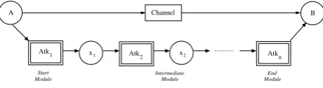
3) End module (E): This is the last module in the attack sequence. It must deliver a frame to the receiving channel place, i.e. B or D. In the attack module this frame comes via place B. There can be zero or one end module in the attack sequence. Modules in this group are: Injection and Replay. The restrictions on how the modules can be combined are summarised as:
For example, a typical modification attack where the attacker modifies a single frame involves an Interception module followed by a Modification module.
To illustrate how the attack modules are integrated into the functional protocol model, assume a simple unordered communication channel (Fig. 3). An attack sequence as shown in Fig. 12 is created as follows. A Start module must be connected to the transmitting place of the channel, i.e. the output arc of placeAis connected to the substitution transition of the attack module; placeA
and placeInputon the attack module page are connected by port-socket relation functions. Intermediate modules can then be added using further substitution transitions, connectingOutputplace of one module to theInputplace of the next. Finally an End module may be added, with
B place in the attack module page connected by a port-socket relation function toB place in the channel.
In Fig. 12, the integrated model provides two possible ways to transmit a token, representing a frame, from place A to B. The first way is send it directly to place
B through the channel transition. If a token takes this path, then it models the normal situation when an attack does not occur. The alternative is that the token passes through the sequence of attack modules. This models the situation of an attack occurring. The direction that the token takes—via the normal channel or via the attacker— is non-deterministic, but the token may take one path or the other, not both (the transitions are in conflict). Note that when the modeller selects specific frames to intercept, then those frames may take theattackpath ornormalpath, while all other frames will take the normal path.
The reason for modelling the attack like this—allowing the frame token to take the normal path or the attack path—is to clearly separate the attacker operations from the normal operations in the CPN. An alternative approach could be to remove the channel transition forcing all tokens through the attack modules. For readability and re-usability, our goal was to minimize the number of changes a modeller would need to make to the original protocol model in order to introduce an attack. Hence we leave
the channeltransition in the model. The outcome of this
is that the state space of the protocol with an attack is a superset of the state space of the protocol without an attack, i.e. our design choice sacrifices state space size for improved readability and re-usability of the model.
Atk1 x1 Atk2 x2 Atkn
B Channel
Intermediate Module A
Module Start
Module End
Fig. 12. Example of Attack Integrated Model
In summary, the steps taken by the modeller in CPN Tools are:
1) Add a sequence of substitution transitions compris-ing a transition for each desired attack module.
2) Connect the substitution transitions via arcs to form a serial chain from channel transmitter place (A or
C) to channel receiver place (Bor D).
3) Edit inscriptions on the attack module pages to suit the specific protocol (e.g. frame types). For convenience to the modeller, the parts to edit are given in comments on each attack module page. This methodology allows the same attack module to be connected repeatedly, since the attack modules in the Start and Intermediate group can be used (connected) more than one time. For example, if we want to modify three different fields in one frame, two options are available. The first option is using three Modification modules, one module for each field. This provides readability to the model but at the expense of increased state space size. Alternatively, the second option is using a single Modification module to modify three fields at the same time by using more complex arc inscriptions. This comes at the expense of readability but does not increase the state space size as much. Our methodology allows the modeller to choose the best suited approach for their needs.
V. ZIGBEERF4CE
The ZigBee Radio Frequency for Customer Electronics (RF4CE) standard [5] allows wireless connectivity in applications in the Customer Electronics domain. Target products are remote controls, input devices, and 3D glasses. Instead of using infrared as a medium, ZigBee RF4CE uses radio frequency that provides benefits such as more reliable, longer distance, two ways communication and non line-of-sight. The Physical and MAC layer of ZigBee RF4CE are based on IEEE 802.15.4 standard, whereas the Network layer protocols are newly defined. The ZigBee RF4CE stack architecture is shown in Fig. 13.
End User Application
Application Profiles
IEEE 802.15.4
Network Layer Data Entity
Network Layer
Entity Management
Fig. 13. ZigBee RF4CE Stack Architecture
Applications use one of the pre-defined profiles to access one of two network layer services. A data transfer service is offered by the Network Layer Data Entity (NLDE), allowing transmission and reception of network protocol data units (NPDUs). A management service is offered by the Network Layer Management Entity (NLME) allowing:
• Service discovery: Find other suitable nodes to pair to
• Pairing: Create a link between a pair of nodes to allow data transfer
• Node initialization: Allow a node to configure its
own stack as a controller node or target node, and start a network
• NIB attribute manipulation: Manage the Network Information Base (NIB) attribute from the NLME This case study, and subsequent description, focuses on the pairing mechanism in the NLME. Only features relevant to the modelling/analysis tasks are described; for a full treatment of ZigBee RF4CE see [5].
A. Pairing
Before nodes can communicate with each other a pairing link must exist between the two nodes, originator and recipient. A pairing request is one of the services permitted by NLME to create a pairing link between nodes. The recipient node can choose whether to accept or reject the pair and confirms the pairing request back to the originator node.
Frames can be sent by a number of transmission options: acknowledged or unacknowledged; unicast or broadcast; single or multiple channel. In this case study we assume acknowledged unicast across a single channel. To communicate between layers of an entity, ZigBee RF4CE use the concept of service primitives which have four types; Request, Indication, Response, andConfirm. These primitives are used in many other protocols (e.g. see [21]).
Different command frame types are used in ZigBee RF4CE. A pair request command frame allows a de-vice to request to pair with another dede-vice, while a
pair response command frame allows a device to
re-spond to a pair request and pass information relevant to the pairing link back to the originator. If the security is required, the key seed command frame is used to exchange security key seed values with a remote device in order to generate a security link key. A ping request
command frame allows a device to send a ping command frame to another device and get a response. Similarly,
a ping response command frame allows a device to
respond to a ping request command frame from another device.
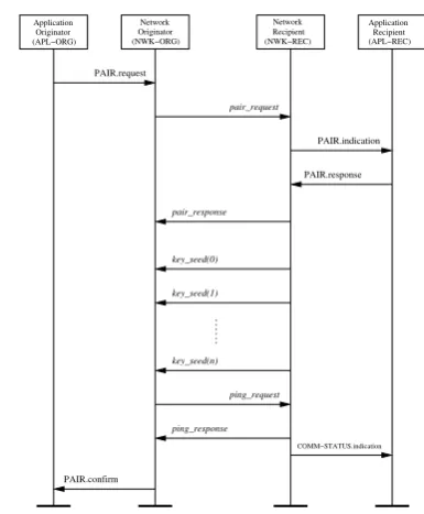
An example successful pairing attempt with security support, referred to as secure mode, is illustrated in Fig. 14. We use this example to explain the typical operation of pairing. In this message sequence chart, primitives are shown in normal style while over the air command frames are labeled in italic text.
From Fig. 14, the application at the originator issues
a PAIR.request primitive triggering a pair requestframe
to be sent to the receiver. Upon reception, the NLME informs the application on the recipient of the request, which then issues a PAIR.response primitive containing its decision whether to accept or reject the pair. The re-sponse is conveyed to the originator in thepair response
frame with a status field that indicates its decision. If rejected (not shown in Fig. 14) a status field is set
to NOT PERMITTED and the pairing is terminated. If
accepted the status field is set to SUCCESS and as
Application Originator (APL−ORG)
Network Originator
(NWK−ORG) (NWK−REC) Network Recipient
(APL−REC) Application Recipient
PAIR.request
PAIR.confirm
PAIR.indication
PAIR.response
COMM−STATUS.indication
key_seed(n) pair_request
key_seed(0)
key_seed(1)
ping_request
ping_response pair_response
Fig. 14. Message Sequence Chart for Pairing
security is required for pairing (secured mode is in use), the recipient will send a number of key seed frames. Once the originator receives all of the key seed frames, it will generate the security link key and transmit the
ping requestframe encrypted with that key. On receipt of
the ping request frame, the recipient verifies that frame
and sends a ping response frame back to the origi-nator. The originator verifies the ping response frame.
PAIR.confirm and COMM.indication primitives are sent
to application layer of each side to indicate the status of pairing. Another alternative configuration of pairing is
un-secured mode, where security is not required for pairing,
and the process of sending key seed, ping request and
ping response frames are omitted.
If the pairing was successful, both sides store the entry of the paired side in their respective pairing tables. Each entry in the pairing table contains all the information necessary for the network layer to transmit a frame to the another side (The format of pairing table is given in Table 49 of [5]).
If a frame is unsuccessfully sent to another side (i.e. timeout occurs or frame errors), the pairing process is stopped and the entry in the pairing table is removed.
VI. CPN MODEL OFPAIRING INZIGBEERF4CE
To demonstrate our proposed methodology, a CPN model of ZigBee RF4CE pairing has been created. This section outlines the design of the functional protocol model and the integration of two example attacks to form the security protocol model. Section VII presents analysis results. All modelling and analysis is performed using CPN Tools.
A. Model Structure
which in fact represent a CPN on a sub-page. The hierarchy is shown in Fig. 15. Two entities of the protocol, ORG (originator) and REC (recipient), are separated in the second level. Four sub-pages of each entity model detail of: passing the primitives between application layer and network layer; managing the network layer process such as generating frames and handling timeouts; transmit frames to another entity; and receive frames from another entity. In total there are 16 places and 56 transitions. Important declarations used in the model are shown in Fig. 16. NWK State and Enumerations are enumerate colour set used to keep network’s state name and all enumerations (list in Table 45 of [5]), respectively. Colour sets in group SERVICE PRIMITIVES are typed record
and used to record the semantics of primitives listing in Section 3 of [5].Field, also typedrecord, is used to record field’s values of the command frame showing in Section 3.2.2.2 of [5]. The details of key pages are described in Section VI-B.
REC RF4CE
ORG
ORG_NLME_SAP
ORG_NWK_Process
ORG_Tx_Frame
ORG_Rx_Frame
REC_NLME_SAP
REC_Tx_Frame REC_NWK_Process
REC_Rx_Frame
Fig. 15. Module Heirarchy of ZigBee RF4CE CPN Model
B. Model Description
Fig. 17 shows the Protocol page of the model, which illustrates the frame flow between protocol entities. The model comprises three main parts: theORG, theRECand a bidirectional communication medium,Ch1andCh2, in the middle.
a) ORG: The ORG page, shown in Fig. 18, consists
of five places, four substitution transitions and their in-terconnecting arcs. APL ORG and NWK ORG Primitive
places are typed by PRIMITIVE colour set and used to store the service primitives in the application layer and
(*PROTOCOL STATE*)
colset NWK State = with idle|pair req sent|pair req sent success|... (*ENUMERATIONS*)
colset Enumerations = with SUCCESS|NO RESPONSE|... (*SERVICE PRIMITIVES*)
colset PAIR REQ = record LogicalCh : UNIT∗DstIEEEAddr : UNIT∗... colset PAIR IND = record Status : status∗SrcPANId : UNIT∗... colset PAIR RES = record Status : status∗DstPANId : UNIT∗... colset PAIR CON = record Status : status∗PairingRef : INT∗... colset COMM IND = record PairingRef : INT∗DstPANId : UNIT∗... (*NWK CMD FIELD*)
colset Field = record ft : FrameType∗fc : FrameCounter∗... (*FRAMES*)
colset Entity = with A|B; colset SignKey = STRING; colset EncryptKey = STRING;
colset Frame = record sender : Entity∗receiver : Entity∗field : Field∗... colset Frames = list Frame;
Fig. 16. Selected ZigBee RF4CE Declarations
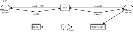
nwkQ4 nwkQ4^^[f]
nwkQ3 f::nwkQ3 nwkQ2 nwkQ2^^[f]
nwkQ1 f::nwkQ1
REC REC ORG
ORG
Ch2 Ch1
D 1`[]
Frames C
1`[]
Frames
B 1`[]
Frames A
1`[]
Frames
ORG
REC
Fig. 17. Protocol page of ZigBee RF4CE CPN Model
the network layer, respectively. The APL ORGplace has an initial marking of onePAIR REQtoken, indicating that the originator is ready to start the pairing request service.
The NWK ORG Frame place stores command frames,
which is either the frames to be sent to the recipient through place A or the frames to be received from the recipient through place C. These places are typed by
Framescolour set and has an initial marking of an empty
list (1‘[]).
ORG NLME SAP substitution transition models the
transmission and reception of service primitives between application layer and network layer.ORG NWK Process
substitution transition models the internal mechanism of the network layer, i.e. checking the capacity of pairing table, generating network command frames, and handling timeouts. ORG Tx Frame and ORG Rx Frame substi-tution transitions model the transmission and reception of the network command frames to/from the recipient entity. In the ORG NWK Process, ORG Tx Frame, and
ORG Rx Frame substitution transitions, there are two
additional places: NWK ORG PT represents the state of pairing table; and NWK ORG STATE represents the current state of the protocol.
C I/O Frames
1`[]
Frames PRIMITIVE
1`PAIR_REQ(Gen_PAIR_REQ())
PRIMITIVE
A I/O Frames I/O I/O
ORG_Rx_Frame
ORG Rx Frame ORG Rx Frame
ORG_Tx_Frame
ORG Tx Frame ORG Tx Frame NWK_ORG_Frame
ORG_NWK_Process
ORG NWK Process ORG NWK Process NWK_ORG_Primitive
ORG_NLME_SAP
ORG NLME SAP ORG NLME SAP APL_ORG
b) REC: For the recipient side, the mechanism of places and substitution transitions are similar to the orig-inator side but changes the label from ORG to REC.
c) Communication Medium: The underlying
com-munication medium is modelled as a bidirectional channel with FIFO queue consisting of four places:A; B;C; and
D, and two transitions:Ch1andCh2. The communication channels allow frames to be lost. The loss behaviour can correspond to either loss in the network (due to the congestion in the network), or to discarding the frames due to the checksum failure.
C. Model with Attacks
After a protocol model is created, the protocol modeller can choose the attack modules from library and integrate them into communication channel in both directions. We illustrate two example attacks in this section.
1) One Way Attack: The first example illustrates an
attack that occurs in one direction (recipient to originator). Between the pairing process an attacker tries to intercept a
pair responseframe from a recipient and then modify the
status field from SUCCESS to NOT PERMITTED (this status field is sent when the recipient does not want to accept the pair). Thereby the originator believes that the recipient does not accept the pairing request and then both sides are not synchronized at the end of pairing process. This example one way attack is implemented using three attack modules: Interception, Modification, and In-jection. These modules are integrated into the ZigBee RF4CE functional protocol model at the communication channel (Ch2 part) as shown in Fig. 19.
nwkQ4
nwkQ4^^[f] f::nwkQ3
nwkQ3
Inject
Injection ModificationModify InterceptionIntercept Ch2
y UNIT
x UNIT C
I/O 1`[]
Frames
D I/O
1`[]
Frames I/O I/O
Injection Modification Interception
Fig. 19. One Way Attack
The modeller must perform three steps to integrate the attack modules:
1) Connect the modules together via their Input and
Output places, as well as to the communication
channel places. For example, in Modification, the
Input and Output places of this module are
con-nected with x and y places of the communication channel (Ch2) subpage by a port-socket relation function, respectively.
2) Change arc inscriptions of the modules to suit the specific protocol following the given instructions in the attack module page.
3) Optionally, specify the initial marking of the Filter
place in each module to apply the module on only selected frames. For example, in the Modification module the initial marking is set to1‘Pair response
as only modification of pair response frames are considered in this attack.
These three attack modules are applied to model the attack that describe above. As an example, the detail of Modification module which integrated in Fig. 19 is shown in Fig. 20. The Input place and Output place of this attack module are linked with x and y places, respectively. The Filterplace has colour set of type
Com-mandIdentifiersince the attacker wants to modify only the
pair response frame, so this place has an initial marking
of 1‘Pair response and it will be filtered by a guard at
Select transition. After frame selection only the selected
frame,pair response, will modify at theModifytransition, with the modified frame stored in theAfter place.
1`()
f f
f
cmd
Modify Select
Frame UNIT
UNIT
To be Modify
Frame
1`Pair_response
CommandIdentifier Frame
[#cmd_id (#field f) = cmd]
Before Attacker DB Attacker DB
After Attacker DB Attacker DB
Filter 1`() Input In In
Output Out
Out Frame.set_field f { ft=(#ft (#field f)), fc=(#fc (#field f)), cmd_id=(#cmd_id (#field f)), status=NOT_PERMITTED, key=(#key (#field f)), mic=(#mic (#field f))}
Fig. 20. Modification Module in One Way Attack
2) Two Ways Attack: The second example illustrates an
attack that occurs in both directions of the communication channel. In this attack the attacker wants the originator to remove the recipient’s entry in a pairing table due to the
pair responseframe being lost (dropped by the attacker).
Meanwhile the attacker also wants the recipient to believe that thepair responseframe arrives at the originator side perfectly. By doing this at the end of pairing process the originator and the recipient are not synchronized.
There are two steps for this attack, as shown in Fig. 21 and Fig. 22. The attacker can achieve the goal by intercepting and dropping apair responseframe from the recipient entity. This attack sequence is shown in Fig. 22. After that the attacker will intercept a new
pair request frame from the originator entity, generate
a bogus acknowledgement frame and inject it to the recipient side. This is shown in Fig. 21.
To control the state space size (not to lead to infinite size of state space), the number of a generated bogus acknowledgement frame will be limited from the Limit place in Generation module by putting the initial marking of one in theLimit place.
nwkQ2 nwkQ2^^[f] f::nwkQ1
nwkQ1
Injection Injection MSG Generation
MSG Generation Ch1
yy UNIT
xx UNIT
B I/O
1`[]
Frames A
I/O 1`[]
Frames
I/O I/O
Injection MSG Generation
Interception Interception Interception
Fig. 21. Two Ways Attack (Ch1 Subpage)
VII. ANALYSIS OFZIGBEERF4CE
nwkQ4^^[f] f::nwkQ3 Ch2
UNIT C
I/O 1`[]
Frames
D I/O
1`[]
Frames I/O I/O
nwkQ3 nwkQ4
Intercept Interception Interception x
Drop Drop Drop
Fig. 22. Two Ways Attack (Ch2 Subpage)
functional model and then two instances of the security model (for the two example attacks).
A. ZigBee RF4CE Functional Analysis
The aim of applying state space analysis on the func-tional model is to prove the absence of unexpected dead (or terminal) markings in the model. For pairing in ZigBee RF4CE the final state of this procedure must end up with both entities, originator and recipient, having an entry in the pairing table that contains information of the paired entity. Therefore we define an unexpected dead marking as any terminal marking in which the entities have different pairing tables.
State space analysis has been applied on the func-tional model in two different configurations: secured and unsecured mode. The size of each state space and the number of all and unexpected dead markings are given in Table VII-A.
TABLE I
FUNCTIONALANALYSISRESULTS
Mode Nodes Arcs All Dead Unexpected Markings Dead Markings
Unsecured 452 1041 9 1
Secured 826 1872 21 1
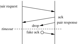
Both unexpected dead markings in the two configura-tions are due to the loss of the final acknowledgement. Fig. 23 illustrates the scenario. The recipient sends the final ACK and therefore assumes the pairing is complete. However the ACK is lost and the originator deletes the pairing entry (after a timeout) assuming the pairing is unsuccessful.
pair request
ack pair response
ack
ping request
ack
ack
ping response pair request
loss
loss
Unsecured Mode Secured Mode
Fig. 23. Example scenario of unexpected behaviour of pairing
B. ZigBee RF4CE Security Analysis
The aim of applying state space analysis on the security model is to prove that an attack is unsuccessful. For both example attacks considered in this case study success is measured by the pairing table entries in the two entities
to differ. As for the functional model, we aim to prove absence of unexpected dead markings. The state space results for both attacks in both secured and unsecured configurations are shown in Table II.
TABLE II
SECURITYANALYSISRESULTS
All Dead Normal Additional
Mode Nodes Arcs Markings Unexpected Unexpected
Dead Markings Dead Markings One Way
Attack 770 1905 14 1 1
Unsecured One Way
Attack 1174 2797 27 2 0
Secured Two Ways
Attack 3303 10457 20 1 2
Unsecured Two Ways
Attack 5985 18311 39 2 0
Secured
The unexpected dead markings are divided into two groups depending on whether or not they are the same as the unexpected dead markings identified in the functional analysis.
When the one-way attack is applied there is one addi-tional unexpected dead markings in unsecured mode. The recipient accepts the pairing request from the originator and responds back via thepair responseframe with status field SUCCESS. However this pair response frame is intercepted and modified by the attacker, changing the status field to NOT PERMITTED. When the originator receives the pair response frame, it will remove the pairing table from its memory while the pairing table at the recipient side, which is already created, is not removed. As a result the two entities finish with different pairing tables.
In secured mode this attack is not successful because the subsequent key seed is ignored by the originator (which believes the session to be over because of the fake
NOT PERMITTEDreceived) and eventually the recipient
times out waiting for a response and removes the pairing table entry. Therefore both entities have an empty pairing table.
When the two-way attack is applied there are two additional unexpected dead markings in unsecured mode. The cause is similar to the one way attack. Fig. 24 illustrates an example scenario that leads to the unex-pected dead marking. Although anAckframe is received by the originator, it is still waiting for a pair response. The attacker drops the pair response, but injects a fake
frame is received by the originator after a timeout).
pair request
ack pair response drop
fake ack timeout
Fig. 24. Example scenario of unexpected behaviour in Two Ways Attack
In secured mode this attack is not successful because, as with the one-way attack, thekey seedis ignored by the originator. Hence the recipient will not receive a response, and eventually remove the pairing table entry.
C. Discussion
This case study has shown how to apply our method-ology to incorporate attacks into a functional protocol model. Although the case study focusses on a small part of a ZigBee RF4CE it demonstrates attacks can be easily integrated and functional and security analysis conducted on the model state space.
The results obtained from the functional analysis in Section VII-A illustrate that problems occur in ZigBee if the final acknowledgement frame is lost. This problem is not unique to ZigBee it can occur in many protocols, and is related to the Byzantine General’s problem. In ZigBee it is likely that the error will be detected in phases subsequent to pairing. For example, if one entity belives the pairing is successful, while the other does not, then communications in subsequent phases will result in an error, and the pairing should be cancelled.
For the result in Section VII-B, which come from the security analysis of protocol, at this time there are no known papers or discussion related in ZigBee RF4CE that mention this weakness of the protocols when two entities are not synchronized at the end of the pairing process which caused from the attacker. Hence we believe this is a valuable result from our analysis.
Note the size of the state space without attacks is up to 826 nodes (secured mode), while introducing the attacks increases the state space to 5985 nodes (secured mode, two-way attack). Although the number of nodes is small in both cases (CPN Tools may handle a million nodes) there is still a seven-fold increase from introducing an attack. To investigate the impact of our proposed Filter
place to limit the state space increase, we have calculated the state space for the case when they are not used (the
Limit place is set to one, cannot be removed since it
will generate infinite size of state space). The number of nodes is 13789 nodes. By using the Filter and Limit
places the state space is reduced by a factor of 2.3. Although they require the modeller to make assumptions about the attack, the implementation of Filter and Limit
in our methodology delivers a valuable reduction in the state space size. Restricting some kinds of frames leads to
smaller state space size, at the expense of fewer security attacks analysed. The value of restricting frames depends on the protocol under consideration and the goal of the modeller. There is no one answer in the end the modeller must decide. Our methodology includes the mechanisms to allow the modeller to easily choose one (more attacks or smaller state space). However it should be noted that more many non-trivial protocols, state space size often is a limiting factor of formal analysis, especially with CPNs. Further demonstrations of the methodology are needed to evaluate the benefits to the modeller. Although not reported in this paper, we have applied the methodology on the Andrew RPC protocol, which was also used as an example in the methodology developed in [16]. Our analysis produced the same results as reported in [16] (and originally in [22]). Further case studies are planned in the future.
VIII. CONCLUSION
The purpose of this research is to overcome the limita-tions of the traditional security analysis techniques, in par-ticular making it possible to protocol designers/modellers to perform security analysis without expert knowledge in the analysis techniques. We achieve this by presenting a novel methodology using Coloured Petri nets that offers a graphical modelling language, a library of common security attack modules and automatic property verifi-cation (through state space analysis). The methodology is developed so that models of communication proto-cols and attacks are re-usable, extendable and readable. The library of attack modules developed can be easily composed to form more complex attacks specific to a protocol. Although a modeller using our methodology requires knowledge of security techniques to create an attack model, by using our library of modules they can reduce the time to develop the model. To demonstrate the methodology we apply it to a part of the ZigBee RF4CE protocol (i.e. pairing). Analysis in the presence of two separate attacks reveals unexpected dead markings are caused by the attacks.
In addition to further case studies there are several areas to extend our research. Currently the attack modules are designed for readability, but lead to increased state space sizes. We will consider alternative, more compact models and compare how much they impact on state space size. Then we will extend our methodology to cover more general protocols, in particular multi-party protocols (e.g. routing protocols; key distribution with trusted-third parties).
IX. ACKNOWLEDGEMENT
The authors are grateful to the anonymous referees for their valuable comments and suggestions to improve the presentation of this paper.
REFERENCES
[2] C. Meadows, “Formal methods for cryptographic protocol analy-sis: Emerging issues and trends,”IEEE Journal on Selected Areas in Communications, vol. 21, no. 1, pp. 44–54, January 2003. [3] I. Al-Azzoni, Douglas G. Down and R. Khedri, “Modeling and
verification of cryptographic protocols using Coloured Petri nets and design/cpn,”Nordic Journal of Computing, vol. 12, no. 3, pp. 201–228, June 2005.
[4] S. Long, “Analysis of concurrent security protocols using Colored Petri nets,” inProceedings of International Conference on Net-working and Digital Society, 2009, pp. 227–230.
[5] ZigBee RF4CE Specification Version 1.00, ZigBee Alliance, March 2009.
[6] F. Babich and L. Deotto, “Formal methods for specification and analysis of communication protocols,”IEEE Communications Surveys & Tutorials, vol. 4, no. 1, pp. 2–20, First quarter 2002. [7] Department of Computer Science, University of Aarhus, “CPN
Tools,” Web site: http://wiki.daimi.au.dk/cpntools/.
[8] S. Gordon, L. M. Kristensen and J. Billington, “Verification on a revised WAP wireless transaction protocol,” inProceedings of the International Conference on Application and Theory of Petri Nets, Adelaide, Australia, June 2002, pp. 182–202.
[9] L. Liu and J. Billington, “Verification of the capability exchange signalling protocol,”International Journal on Software Tools for Technology Transfer, vol. 9, no. 3-4, pp. 305–326, June 2007. [10] S. Suriadi, C. Ouyang, J. Smith and E. Foo, “Modeling and
verification of privacy enhancing protocols,” inProceedings of the 11th International Conference of Formal Engineering Methods: Formal Methods and Software Engineering, 2009, pp. 127–146. [11] S. Gordon and S. Choosang, “Verification of the FlexRay transport
protocol for autosar in-vehicle communications,” International Journal of Vehicular Technology, vol. 2010, 2010.
[12] F. Erbas, K. Kyamakya and K. Jobmann, “Modelling and per-formance analysis of a novel position-based reliable unicast and multicast routing method using Coloured Petri nets,” in Proceed-ings of the 58th IEEE Vehicular Technology Conference, October 2003, pp. 3099–3104.
[13] L. zhang Zhu and H. Zhang, “Queuing network models analysis based on CPN,” inProceedings of the 2nd International Confer-ence on Information and Computing SciConfer-ence, May 2009, pp. 269– 272.
[14] S. Korecko, B. Sobota and C. Szabo, “Performance analysis of processes by automated simulation of Coloured Petri nets,” in
Proceedings of the 10th International Conference on Intelligent Systems Design and Applications, November 2010, pp. 176–181. [15] L. Liu, “Uncovering SIP vulnerabilities to DoS attacks using Coloured Petri nets,” inProceedings of the 10th IEEE International Conference on Trust, Security and Privacy in Computing and Communications, 2011, pp. 29–36.
[16] Y. Xu and X. Xie, “Modeling and analysis of security protocols using Coloured Petri nets,”Journal of Computers, vol. 6, no. 1, pp. 19–27, January 2011.
[17] Y. Permpoontanalarp, “On-the-fly trace generation and textual trace analysis and their applications to the analysis of crypto-graphic protocols,” inProceedings of the 30th Formal Techniques for Networked and Distributed Systems, Amsterdam, June 2010. [18] Y. Permpoontanalarp and P. Sornkhom, “A new Coloured Petri net
methodology for the security analysis of cryptographic protocols,” inProceedings of the 10th Workshop and Tutorial on Practical Use of Coloured Petri Nets and the CPN Tools, Aarhus, Denmark, October 2009.
[19] J. Billington, G. E. Gallasch, and B. Han, “A Coloured Petri net approach to protocol verification,” inLectures on Concurrency and Petri Nets, Advances in Petri Nets. Springer-Verlag, 2004, pp. 210–290.
[20] D. Dolev and A. Yao, “On the security of public key protocols,”
IEEE Transactions on Information Theory, vol. 29, no. 2, pp. 198– 208, March 1983.
[21] David E. Carlson, “ANSI/IEEE 802.2, 1998 edition.”
[22] G. Lowe, “Some new attacks upon security protocols,” in Proceed-ings of the 9th IEEE Workshop Computer Security Foundations, 1996, pp. 162–169.
San Choosangreceived a B.Sc. in computer
science from Sirindhorn International Institute of Technology, Thammasat University, 2010, Thailand. He has been a Certified Cisco Sys-tem Instructor at the Network Training Cen-ter Co.,Ltd., Thailand. He is currently a M.S student in Sirindhorn International Institute of Technology, Thammasat University, Thai-land. His research interests include: computer networking; formal analysis of protocols and Internet security protocols.
Steven Gordonobtained a Ph.D. in