Design and Testing of Drop off Plate for Low
Pressure Safety Devices validated to FE analysis
Prakash V. Ghelani Prof. M.I. Vyas
PG Student Associate Professor
Department of Mechanical Engineering Department of Mechanical Engineering L.D. College of Engineering L.D. College of Engineering
Abstract
Safety valve in an industry often acts as the primary device to prevent catastrophic failure under pressure conditions. When cryogenic storage is considered, the safety valves used are of first concern as the storage is carried out at very low pressure and high mass flow rate. The commercially available safety valves for outer vacuum jacket cryogenic storage vessel are not compatible with lower pressure range of 1.2 bar. The low pressure safety valves are needed for such low pressure applications. The design of drop off device for low pressure applications has been considered in this project. Modelling and analysis of the design is done and further the creation of a working model of the same followed by testing of the model. Testing of conventional drop off device is also done to ensure the performance of the model created.
Keywords: Low Pressure, Cryogenic Storage Vessel, Drop plate, Bursting Disk, CFD
________________________________________________________________________________________________________
I.
INTRODUCTION
The primary function of a safety valve is to protect property and life. Because a safety valve is often the primary device to prevent catastrophic failure under pressure conditions, it is important that the valve works at all times i.e. it must be 100% reliable. Safety valves should be installed wherever the maximum allowable working pressure of a system or pressure containing vessel is likely to be exceeded, in particular under fault conditions due to the failure of another piece of equipment in the system. Pressure excess can be generated in a number of different ways including: Failure of a cooling system allowing vapor or fluid to expand Compressed air or electrical power failure to control instrumentation Plant fires during the start-up conditions of a plant unexpected chemical reactions in chemical plants.
Cryogenic liquid containers, also referred to as liquid cylinders, are double-walled, vacuum vessels with multilayer insulation in the annular space. They are designed for the reliable and economic transportation and storage of liquefied gases at cryogenic temperatures, typically colder than –130°F (–90°C). There are two primary advantages of a liquid container. The first is that it contains a large volume of gas at a relatively low pressure compared to a compressed gas cylinder. The second is that it provides a source of cryogenic liquids which can be easily handled. Cryogenic liquid containers are often incorrectly referred to as Dewars. Dewars are open, non-pressurized vessels for holding cryogenic liquids.
All cryogenic liquids produce large volumes of gas when they vaporize. The expansion ratio is the amount of gas generated from a given amount of liquid. If a sufficient amount of liquid is vaporized within a closed container, it will produce enormous pressures that could rupture the vessel. For this reason, cryogenic liquid containers are protected with multiple pressure relief devices. Similarly, any system for the storage and delivery of cryogenic liquids should be carefully designed to avoid trapping cryogenic liquid at any point in the system by installing a relief device.
II.
DESIGN METHODOLOGY
Design of Shell: A.
For designing of shell the following assumptions are made for safe design. 1) Shell length is 1500 mm which is predetermined by design limitation. 2) Shell internal design pressure is 3 bar and outside design pressure 1 bar.
3) Shell outside diameter is taken 457 mm required to calculate inside diameter and shell thickness.
By above assumptions and following section VIII division 1 of American Society of Mechanical Engineering (A.S.M.E.) following results are obtained.
Table - 1 Shell Calculation Result
Symbol Description Unit Value
Pi Internal pressure of vacuum jacket Bar 3
Do Outside diameter of the shell mm 457
t Shell wall thickness Mm 4.19
e Head thickness Mm 10.05398248
T Design temperature °C 27
P Design maximum/minimum allowable working pressure Bar 4.55
S Maximum allowable stress in tension Mpa 16700
Do/t Ratio Unit less 109.0692124
L/Do Ratio Unit less 3.282275711
A Factor derived from chart Unit less 0.00038
B Factor derived from chart unit less 5400
Design of Drop Plate: B.
This device is design according to standard EN 13458.
Following is the design procedure of drop plate in that we take bore diameter as per standard NB 2 inch for flange design and SCH 10 is required for Pipe size
Fig. 1: Drop Plate with Flange
For SCH 10, we obtained following dimension of the flange of 2 inch bore pipe and flange standard flange dimention150 Table - 2
Dimension of 2” Pipe Standard Flange Sr. No Dimensions Unit Size
1 Size NB mm 50.8
2 Outer diameter mm 60.3
3 Thickness mm 2.77
4 ɸ ‘A’ mm 54.76
5 ɸ ‘E’ mm 66.35
6 ɸ ‘C’ mm 90
7 ɸ ‘D’ mm 110
8 D mm 9
9 P mm 5.03
11 Threading M8
As we know that we have design internal pressure 1.2 bar and external pressure is 1 bar so, according to that pressure our drop of plate should lift in case of internal pressure rise. So force balance between internal and external pressure condition is carried out as following:
1) Force balance:
Fig. 2: Drop Plate Design 2) Volume of Drop Plate:
The value of a and c is decided in such a way that the mass of the drop plate would be minimum. The results below are obtained by above mentioned procedure.
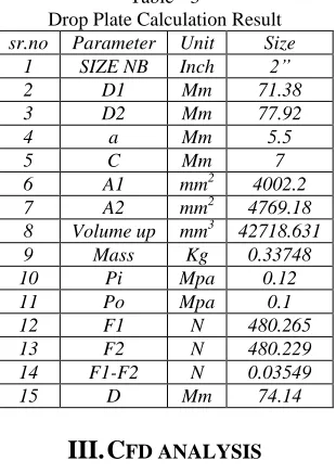
Table - 3
Drop Plate Calculation Result sr.no Parameter Unit Size
1 SIZE NB Inch 2”
2 D1 Mm 71.38
3 D2 Mm 77.92
4 a Mm 5.5
5 C Mm 7
6 A1 mm2 4002.2
7 A2 mm2 4769.18
8 Volume up mm3 42718.631
9 Mass Kg 0.33748
10 Pi Mpa 0.12
11 Po Mpa 0.1
12 F1 N 480.265
13 F2 N 480.229
14 F1-F2 N 0.03549
15 D Mm 74.14
III.
CFD ANALYSIS
ANSYS Fluent is very renowned software for caring out CFD analysis. So, all simulations and analysis in this paper are also performed by this software package. Same as most other CFD tools ANSYS Fluent also is also divided in three main parts. Pre Processor, Solver and Post processor.
Pre Processor: A.
In the starting, it is necessary to define geometry and topology of working fluid and surrounding solid parts. For that 3D model is generated in ANSYS Design Model.
Fig. 3 & 4: Front View and Orthographic View of Drop off Device Assembly
As shown in figures a 3D model is generated using ANSYS design model tool. The main parts of the assembly are drop plate, flange, cover plate, end plate etc.
After generating the 3D model next step is to define the geometry. So the surface from which the fluid will enter into the geometry is defined as ‘inlet’ and the surface opposite to the ‘inlet’ surface or from which the fluid will come out is defined as ‘outlet’ by same manner.
Next step is to generate the mesh. It can be done by clicking on the tab named as ‘generate mesh’. While generating mesh different mesh controlling parameters can be inserted to generate mesh to match with desired criteria. For this analysis 10 Node Quadratic Tetrahedron type of mesh is used.
Fig. 5: Meshing on Drop off Plate Device
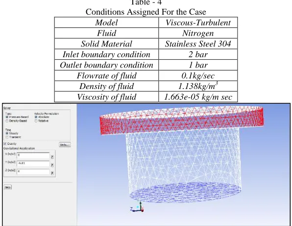
Table - 4
Conditions Assigned For the Case
Model Viscous-Turbulent
Fluid Nitrogen
Solid Material Stainless Steel 304 Inlet boundary condition 2 bar Outlet boundary condition 1 bar Flowrate of fluid 0.1kg/sec
Density of fluid 1.138kg/m3 Viscosity of fluid 1.663e-05 kg/m sec
Fig. 6: Applying Gravity Force to Drop off Device
Fig. 7: Boundary Conditions and Fluid Inlet Flow Conditions
Solver: B.
After assigning all the required data, solving process starts. First solution is initialized for calculating the initial data. Number of iterations to be solved are allocated and setup is started. ANSYS shows the graph of residuals vs. iterations while solving the process. When values of residuals declines from assigned criteria, solution gets converged.
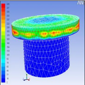
Post Processing: C.
It is used for the analysis and visualization of the resulting solution. Graphs, contours, streamlines etc. can be generated and plotted in this module. Results of current case can be are shown in the following figures.
Fig. 9: Velocity Profile
Fig. 10: Velocity Profile with Turbulence Flow
Fig. 11: Turbulence Profile with Values of Energy
IV.
FINITE ELEMENT MECHANICAL ANALYSIS
For understanding the material properties of the device in environment conditions analysis of the device has been carried out in ANSYS Workbench 14.0. Same as the CFD analysis this analysis has also been categorized into three parts: Pre Processing, solver and Post processing.
The detailed analysis is as followed,
Mesh Details: A.
Table – 6 Elements Type Summary
Generic Element Type Name Ansys Name Description
10 Node Quadratic Tetrahedron Solid187 10 Node Tetrahedral Structural Solid
20 Node Quadratic Hexahedron Solid186 20 Node Structural Solid
Fig. 12 & 13: Meshing for Mechanical Analysis of Drop-Off Device Assembly
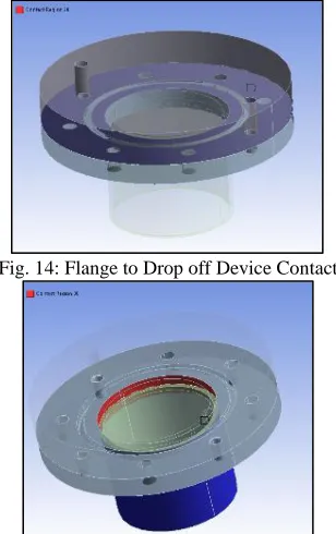
Constraints: B.
Fig. 14: Flange to Drop off Device Contact
Fig. 15: Pipe to Flange Contact
Thermal Analysis: C.
Fig. 17: Top of Device – 308 K (Room Temp)
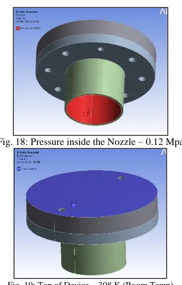
Structural Analysis (Design condition): D.
Fig. 18: Pressure inside the Nozzle – 0.12 Mpa
Fig. 19: Top of Device – 308 K (Room Temp)
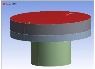
Structural Analysis (Due to Vacuum condition – Collapsible Case): E.
Fig. 21: Pressure on the device (0.2 Mpa – (Atm + Vacuum))
Results: F.
Fig. 22: Temperature Profile Fig.23: Total Deformation Under Design Condition
Fig. 24 & 25: Maximum Von Mises Stress In Design Condition
V.
CONCLUSION
1) During the CFD analysis the overpressure is under limit as per the set pressure of drop off device. It doesn’t increase suddenly. So no over pressure occurs. Only turbulence occurs at the outlet of drop off device in small area.
2) During mechanical analysis for all load cases, the stresses are well within the allowable stress for the entire area.
REFERENCES
[1] Preliminary analysis of an innovative type of low pressure valves ,K.Klarecki, journal of achievements in materials and manufacturing engineering, Volume 41, issue1-2, July-august 2010.
[2] The dynamic response of pressure relief valves in vapor or gas service. Part II: Experimental investigation by A.A. Alderb, Ron Darby, Scott Arndt. Journal of Loss Prevention in the Process Industries, June 2014.
[3] Backpressure in a high-lift compensated pressure relief valve subject to single phase compressible flow J. Francis, P.L. Betts Journal of Loss Prevention in the Process Industries 11 (1998) 55–66.
[4] Development of a variable quench pressure relief valve for superconducting magnet system. Kimura a, H. Ohhata, T. Okamura, Y. Makida, H. Yoshida, Cryogenics 51 (2011) 465–469.
[5] Study on effect of liquid level on the heat leak into vertical cryogenic vessels, Yang Li, Rongshun Wang, and Caili Wang, Cryogenics 50 (2010) 367–372. [6] Temilade Ladokun, Farhad Nabhaniand Sara Zarei, Accidents in Pressure Vessels: Hazard Awareness, London, U.K., Proceedings of the World Congress
on Engineering 2010 Vol II WCE 2010, June 30 - July 2, 2010.
[7] Kaganer MG, Thermal insulation in low temperature techniques, Moscow: mashinostroenie, Russia 1996. [8] Relief valve, From Wikipedia, the free encyclopedia.
[9] Product brochure of Breetec International N.V. Steenweg 210b-3665 As
[10] Pressure Relief Valve Selection And Sizing (Engineering Design Guidelines), KLMT, technology Group,3-12 Block Aronia, Jalan Sri Perkasa 2,Taman Tampoi Utama,81200 Johor Bahru,Malaysia
[11] Randall f Barron, cryogenic system, Oxford Press, London, 1987.
[12] G.G. Haselden, Cryogenic fundamentals, academic press, London and New York. [13] Design and safety data book, Air liquid specialty America LLC.
[14] Reference guide for O-Ring materials, MRS.