INTERNATIONAL JOURNAL OF ENGINEERING SCIENCES &
MANAGEMENT
SUPRESSION OF LOW FREQUENCY OSCILLATIONS(LFO) IN THE
POWER SYSTEM BY NUERO FUZZY LOGIC CONTROLLER
K.V.V.Sai Babu*, U.Sravya
*II M.Tech, Department of EEE, DVR & Dr.HS MIC College of Technology, Kanchikacherla,
Krishna DT
Assistant Professor, Department of EEE, DVR & Dr.HS MIC College of Technology,
Kanchikacherla, Krishna DT
ABSTRACT
Low-frequency oscillations (LPF) in electric power systems due to the uncontrollability of the disturbance in the power system. These oscillations need to be controlled to maintain system stability. Several control devices, such as power system stabilizers, lead lag controllers are used to enhance power system stability. The UPFC can be used to effectively control these low-frequency power system oscillations. It is done by designing a supplementary signal based on either the real power flow along the transmission line to the series converter side or to the shunt converter side through the modulation of the voltage magnitude reference signal. In this work the linearized model of synchronous machine connected to infinite bus (Single Machine-Infinite Bus: SMIB) with UPFC, adaptive neuro-fuzzy controller for UPFC is designed and simulated to suppress the low frequency oscillations. Simulation is performed on the characteristics of the fuzzy controlled bus system. It is evident that the fuzzy logic controller has effective operation than the conventional lead-lag controller through the obtained results.
Keywords: Neuro-Fuzzy Controller, Low Frequency Oscillations (LFO), Unified Power Flow Controller (UPFC), Single Machine-Infinite Bus (SMIB)..
INTRODUCTION
There is no single acceptable definition of the term electric power quality. The term generally applies to the goodness of the electric power supply, voltage regulation, frequency, voltage wave shape, current wave shape, level of impulses and noise, and the absence of momentary outages [4]. The regulation of the network frequency constitutes one of the essential elements for the “quality” of operation; excessive frequency variations would not, in fact, be tolerated by many end-users, or by auxiliary equipment of the generating power stations themselves [9].The growth of the demand for electrical energy leads to loading the transmission system near their limits. Thus, the un-controlling of the system is leads to develop the frequency oscillation. The damping torque is used to provide the balancing in the system.
FACTS controllers allow steady-state, quasi-steady-state, dynamic, transient control actions and they provide important equipment and system protection functions. The primarily use of UPFC is to control the power flow in power systems. The UPFC consists of two Voltage source converters (VSC) each of them
has two control parameters namely me, δe, mb and δb. For systems which are without power system stabilizer (PSS), excellent damping can be achieved via proper controller design for UPFC parameters. It is usual that Heffron-Philips model [13] is used in power system to study small signal stability. This model has been used for many years providing reliable results. In recent years, the study of UPFC control methods has attracted attentions so that different control approaches are presented for UPFC control such as Fuzzy control, Conventional lead-lag control, Genetic algorithm approach, and robust control methods.
used and the simulation results for the power system including these two controllers are compared with each other.
This paper is organized as follows: in Section II, the model of the power system including UPFC is presented. The proposed Adaptive Neuro-Fuzzy controller and lead-lag compensator are explained in Section III. The results of the simulation are shown in Section IV. Finally conclusions are presented in section V
POWER
SYSTEM
MODEL
INCLUDING UPFC
UPFC is one of the famous FACTS devices that are used to improve power system stability. Fig.1 shows a single-machine-infinite-bus (SMIB) system with UPFC. It is assumed that the UPFC performance is based on pulse width modulation (PWM) converters. In figure 1 me, mb and δe, δb are the amplitude modulation ratio and phase angle of the reference voltage of each voltage source converter respectively [12].
A linearized model of the system is used in dynamic studies of power system [2]. In order to consider the effect of UPFC in damping of LFO, the dynamic model of the UPFC is employed. In this model the resistance and transient of the transformers of the UPFC can be ignored [7]. The representation of the power system equipped with the UPFC can be represented as shown in equation (1) and torque generation of the Heffron Philips model is given by equation (2). The control variables of the system are the speed variation, angle variation in the rotor calculated from the characteristics of the single machine system. These variables are given as the controlling signals to the fuzzy controller [11]. Generally, the study of the synchronous machine is driven from a constant voltage-frequency ratio, the motor develops the same maximum torque at all speeds. For the salient pole rotor this will occurs at the load angle which is influenced by the relative values of Lq and Ld.. The steady state representation
of the torque developed in the salient pole rotor is given as equation (2) .
Fig.1 A single machine connected to infinite bus with UPFC
[ ∆𝛿𝐼
∆𝑤𝐼
∆𝐸𝑞1
∆𝐸𝑓𝑑𝐼
∆𝑉𝑑𝑐𝑖 ]
=
[
0 𝑤0 0 0 0
−𝑘1 𝑀 −𝐷 𝑀 −𝑘2 𝑀 0 −𝑘𝑝𝑑 𝑀 −𝑘4
𝑇𝑑𝑜𝐼 0
−𝑘3 𝑇𝑑𝑜𝐼 1 𝑇𝑑𝑜𝐼 −𝑘𝑞𝑑 𝑇𝑑𝑜𝐼
−𝑘4𝑘5 𝑇𝐴 0
−𝑘𝐴𝑘6 𝑇𝐴
−1 𝑇𝐴
−𝑘𝐴𝑘𝑣𝑑 𝑇𝐴
𝑘7 0 𝑘8 0 −𝑘9 ]
[ ∆𝛿 ∆𝑤 ∆𝐸𝑞𝐼 ∆𝐸𝑓𝑑 ∆𝑣𝑑𝑐] + [ −𝑘𝑝𝑒 𝑀 −𝑘𝑝𝑒𝛿𝑒 𝑀 −𝑘𝑝𝑏 𝑀 −𝑘𝑝𝛿𝑏 𝑀 0 −𝑘𝑞𝑒 𝑇𝑑𝑜𝐼 −𝑘𝑞𝑒𝛿𝑒 𝑇𝑑𝑜𝐼 −𝑘𝑞𝑏 𝑇𝑑𝑜𝐼 −𝑘𝑞𝛿𝑏
𝑇𝑑𝑜𝐼 0
−𝑘𝐴𝑘𝑣𝑒 𝑇𝐴 −𝑘𝐴𝑘𝑣𝛿𝑒 𝑇𝐴 −𝑘𝐴𝑘𝑣𝑏 𝑇𝐴 −𝑘𝐴𝑘𝑣𝛿𝑏
𝑇𝐴 0
𝑘𝑐𝑒 𝑘𝑐∆𝑒 𝑘𝑐𝑏 𝑘𝑐𝛿𝑏 0
0 0 0 0 0]
[ ∆𝑚𝐸 ∆𝛿𝐸 ∆𝑚𝑏 ∆𝛿𝑏 𝑣𝑑𝑐 ] (1)
Where ΔmE, ΔmB, ΔδE and Δδb are the deviation of input control signals of the UPFC.
𝑇 =
3𝑃 𝑤0⌈
𝑉2
𝜆𝑅+𝑉𝐸𝑓𝑜𝜆𝑋𝑞𝑜𝑠𝑖𝑛𝛿+𝑉22(𝑋𝑑𝑜−𝑋𝑞𝑜)𝑠𝑖𝑛2𝛿−𝑉𝑅𝐸𝑓𝑜𝑐𝑜𝑠𝛿
𝑅2+𝜆2𝑋𝑑𝑋𝑞 ⌉
(2)
CONTROLLER DESIGN
The switching of the convertors must be reliable, accurate and effective in the operation in order to control the frequency ranges in the loads, controlling pulses require controlling the variable parameters. Power full control strategies to the convertors required to obtain stable controlled switching with low sensitivity and burden against the controlling parameters.
A) Lead-Lag Controller Design:
Lead lag compensation is used for the good stability margin, having the poor steady state accuracy. The characteristic of lead lag compensator is given by the equation (3).
𝐶𝐿𝐿(𝑆) = 𝑘𝐿𝐿1+𝑠𝑇1+𝑠𝑇𝑧
The compensator selection and design based upon the parameters as given below:
1. Compensator Selection 2. Unity Gain Frequency 3. Desired Phase Margin
4. Compensator Zero-Pole Placement 5. Compensator Gain Calculation 6. Stability Margin Variation 7. Results.
B). Adaptive Neuro-Fuzzy Controller Design
Fuzzy logic controller is the new hybrid technology totally depends upon the human thinking. The controllers easily designed based on the controlling variable are taken as the inputs by taking the sample values. Generally some samples of the values of the controlling parameter variation as the input to the controller and specific function is taken as the expected function of the controller. The main steps in the implementation of a fuzzy logic controller as follows:
1. Fuzzification.
The variation in the speed and angle of the rotor, ∆δ and ∆w as taken as the inputs to the fuzzy controller. In Figure 2, a Sugeno type of fuzzy system has the rule base with rules such as follows [5]:
1. If Δδ is A1 and Δω is B1 then f1=p1 Δδ+q1 Δω+r1.
2. If Δδ is A2 and Δω is B2 then f2=p2 Δδ+q2 Δω+r2.
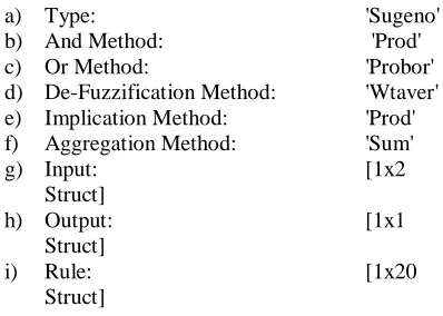
2. Interference Engine:
The result of the fuzzy control algorithm can be obtained by using the control rules, membership functions, and an interference engine.
a) Type: 'Sugeno'
b) And Method: 'Prod'
c) Or Method: 'Probor' d) De-Fuzzification Method: 'Wtaver' e) Implication Method: 'Prod' f) Aggregation Method: 'Sum'
g) Input: [1x2
Struct]
h) Output: [1x1
Struct]
i) Rule: [1x20
Struct]
μA and μB are the membership functions of
fuzzy sets Ai and Bi for i=1… 20. In evaluating the rules, we choose product for T-norm (logical and). Then controller could be designed in following steps
Fig.2 ANFIS architecture for 2 input Sugeno fuzzy model with 20 rules
1) Evaluating the rule premises:
𝑤𝑖= 𝜇𝐴𝑖(∆𝛿)𝜇𝐵𝑖(∆𝑤), 𝑖 = 1,2,3, … 20.
(3)
2) Evaluating the implication and the rule consequences:
𝑓(∆𝛿, ∆𝑤) =
𝑤1(∆𝛿,∆𝑤)𝑓1(∆𝛿,∆𝑤)+⋯….+𝑤20(∆𝛿,∆𝑤)𝑓20(∆𝛿,∆𝑤)
𝑤1(∆𝛿,∆𝑤)+⋯.+𝑤20(∆𝛿,∆𝑤) (4)
Or leaving the arguments out
𝑓 =𝑤1𝑓1+𝑤2𝑓2+⋯.𝑤20𝑓20
𝑤1+𝑤2+⋯𝑤20 (5)
This can be separated to phases by first defining
𝑤𝑖−=𝑤1+𝑤𝑤2+⋯𝑤1 20, 𝑖 = 1,2,3, … 20 (6)
These are called normalized firing strengths. Then f can be written as
𝑓 = 𝑤1−𝑓1+ 𝑤2−𝑓2+ ⋯ . 𝑤20−𝑓20
(7)
The above relation is linear with respect to Pi, Qi
ri and i=1, 20. So parameters can be categorized into
2 set of linear parameters and set of nonlinear parameters. Now Hybrid learning algorithm can be applied to obtain values of parameters. Hybrid learning algorithm is combination of linear and nonlinear parameters learning algorithm. Description for learning procedure can be found in [20]. This network is called adaptive by Jang and it is functionally equivalent to Sugeno type of a fuzzy system. It is not unique presentation. With regard to the explanations presented and with the help of MATLAB software, adaptive neuro-fuzzy controller can be designed. The rules surface for designed controller shown in figure 3. The membership functions for input variable Δω are presented in figure 4and 5.
Fig.3 The rules surface
Fig.4 The membership functions for input variable Δω
Fig.5 The membership functions for input variable Δδ
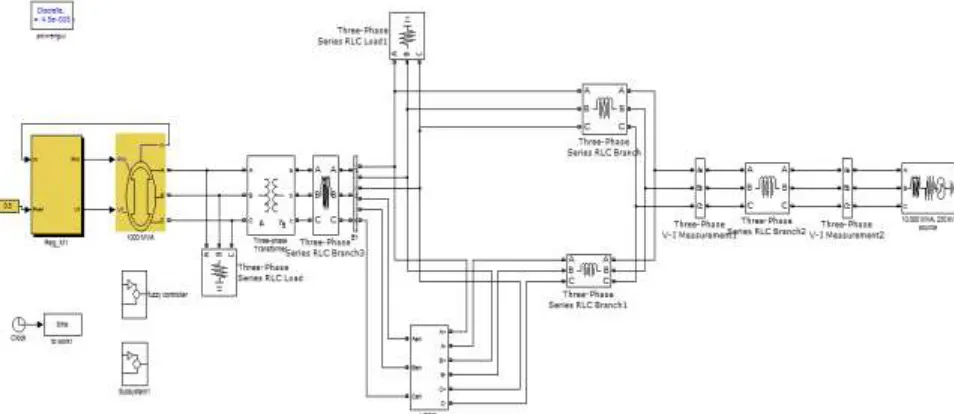
SIMULATION & RESULTS
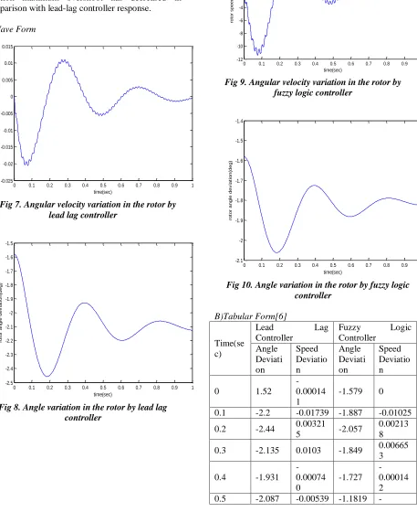
In this work, LFO is linearily controlled by controlling the angular velocity (speed) , rotor angle variation . These values are given as a input to the lead-lag and fuzzy controllers. Its clearly shows form the Fig 7 to that the lead-lag controller response is not as good as neuro-fuzzy controller response and also neuro-fuzzy controller decreases settling time. In addition maximum overshoot has decreased in comparison with lead-lag controller response.
A)Wave Form
Fig 7. Angular velocity variation in the rotor by lead lag controller
Fig 8. Angle variation in the rotor by lead lag controller
Fig 9. Angular velocity variation in the rotor by fuzzy logic controller
Fig 10. Angle variation in the rotor by fuzzy logic controller
B)Tabular Form[6]
Time(se c)
Lead Lag
Controller
Fuzzy Logic Controller Angle Deviati on Speed Deviatio n Angle Deviati on Speed Deviatio n
0 1.52 -0.00014 1
-1.579 0
0.1 -2.2 -0.01739 -1.887 -0.01025
0.2 -2.44 0.00321
5 -2.057
0.00213 8
0.3 -2.135 0.0103 -1.849 0.00665 3
0.4 -1.931 -0.00074 0 -1.727 -0.00014 2 0.5 -2.087 -0.00539 -1.1819
-0 0.1 0.2 0.3 0.4 0.5 0.6 0.7 0.8 0.9 1
-0.025 -0.02 -0.015 -0.01 -0.005 0 0.005 0.01 0.015 time(sec) ro to r s p e e d d e v ia ti o n
0 0.1 0.2 0.3 0.4 0.5 0.6 0.7 0.8 0.9 1
-2.5 -2.4 -2.3 -2.2 -2.1 -2 -1.9 -1.8 -1.7 -1.6 -1.5 time(sec) ro to r a n g le d e v ia ti o n (d e g )
0 0.1 0.2 0.3 0.4 0.5 0.6 0.7 0.8 0.9 1
-12 -10 -8 -6 -4 -2 0 2 4 6
8x 10
-3 time(sec) ro to r s p e e d d e v ia ti o n (d e g )
0 0.1 0.2 0.3 0.4 0.5 0.6 0.7 0.8 0.9 1
0.00303 7
0.6 -2.198
4.89e-006 -1.881 0.00033
0.7 -2.137 0.00294
9 -1.832
0.00192 1
0.8 -2.061 0.00048
26 -1.789 4.8e-005
0.9 -2.086 -0.00132 2
-1.806 0.00090 26
1 -2.125 -0.00011 1
-1.825 0
CONCLUSION
By the comparison of the results, fuzzy logic controller has the effective operation rather than the convenctional lead-lag controllers. By using the adaptive techniques, by the damping torque, low frequency oscillation are reduced and nullified to the steady state operation of the system. Fuzzy logic controllers are desinged to nearest of the humanity and doesn’t require any system paprameters or operating conditions. Fuzzy logic controllers canb be apply to various tpes of convertors and controllers to control the capability, quality of the system. Also we can utilize advantages of neural networks such as the ability of adapting to changes, fault tolerance capability, recovery capability, High-speed processing because of parallel processing and ability to build a DSP chip with VLSI Technology
REFERENCES
1. Li Wang, Senio Dynamic Stability Improvement of an IntegratedGrid-Connected Offshore Wind Farm and Marine-Current Farm using STATCOM,”, IEEE TRANSACTIONS ON POWER SYSTEMS, VOL. 26, NO. 2, MAY 2011. 2. Arrillaga and C. P. Arnold. “Computer
analysis of power systems”, ISBN 0 471 92760 0.
3. Mats Larsson,” Coordinated Voltage Control in Electric Power Systems”, Department of Industrial Electrical Engineering and Automation Lund Institute of Technology.Lund Un iversity.
4. N. G. Hingorani and L. Gyugyi, Understanding FACTS: Concepts and Technology of Flexible AC Transmission System, IEEE Press, 2000.
5. Muhammad H. Rashid,” Power Electronics Handbook”, University of
Florida,University of West Florida Joint Program and Computer Engineering. 6. Dr.Shailendra Jain,”Modelling & Simulation
using Matlab-Simulink” Wiley India Pvt.Ltd.
7. L.L. Grigsby, Andrew Hanson,”Power System Analysis and Simulation”, © 2001 CRC Press LLC
8. Om Nayak, Surya Santoso, Paul Buchanan,’ Power Electronics Spark New Simulation Challenges”.
9. Roger C Ducan, Mark F Mc Granaghan, Surya Santoso,” Electrical Power Systems Quality, Second Edition”.
10. Simone Buso, Paolo Mattavelli,” Digital Control in Power Electronics”, Morgan & Claypool Publishers.