e- ISSN: 2278-067X, p-ISSN: 2278-800X, www.ijerd.com
Volume 14, Issue 5 (May Ver. II 2018), PP.33-37
Design and Analysis of Steering System for E-Bike
1
Sai Krishna Koleti,
2Rahul Reddy Boyapalli And
3Ravi B
1,2Student, Sreenidhi Institute of Science & Tech, Hyderabad, Telangana3Scholar, Department of Mechanical Engineering, Sreenidhi Institute of Science & Tech, Hyderabad, Telangana
Corresponding Author: Sai Krishna Koleti
ABSTRACT: The competitive and ever progressive world made mankind to channel the available natural resources for its own benefit devoid of the unfathomable conditions that would prevail in near future. The fear of running out of fuel reserves, forced mankind to depend on other forms of energy. Electrical energy had been amusing mankind with its diverse ways of existence, with which mankind was successful to exploit this energy in many fields. One of such field that needs generic concern of human kind is automobile engineering. This field had been successfully exploited and the production of electric vehicles was made feasible. E bike known for its advantages over petroleum engine in regards with the emission is likely to emerge in the market and become one of the fastest and progressing vehicle. With the scope of enhancing the performance of the e bike we have channelled efforts of all the team to achieve optimum design in Steering system. The prescribed engineering process for design is documented in the following report, including problem definition, project scheduling, design research, design development, and design analysis. The overall objectives are to increase the vehicle performance, quality and overall efficiency.
The design process of the vehicle was based on several engineering and reverse engineering methods. The following are the parameters that were taken into consideration while designing the steering mechanism, Endurance, Safety and Ergonomics, Availability, Kerb weight, Cost of the Components and Safe Engineering Practices.
We began the process of designing by conducting various researches for main parts of the vehicle. Our team had carried out market research for the desired parts. SOLIDWORKS 2016 was the CAD software used for designing and ANSYS 15.0 was used for analysis of the vehicle. Besides performance, consumer needs of serviceability and affordability were also kept in concern which we got to know through the internet research.
KEYWORDS:Rake, Trial, Opposing Torque, Tree turning angle, Turning radius, Lean angle.
--- --- Date of Submission: 05-05-2018 Date of acceptance: 21-05-2018 ---
---I INTRODUCTION
[1]. Steering is a governing subsystem which is collection of mechanical linkages to help the rider to guide the vehicle in desired direction or to negotiate a turn along circular pathway. Steering system of a two-wheeler involves crucial parameters which determine the stability and manoeuvrability of the vehicle.
A.1,2,3Rake:
[1]. Rake is the angle in degrees of the steering neck from vertical. Rake is a crucial parameter which accounts for the change of trail and front fork lengths. The rake angle is selected for the vehicle prioritizing stability and manoeuvrability.
Rake = 28degrees
B. 1,2,3Trail:
[1]. Trial is the distance defined by the vertical line from axle to ground and the intersection of centreline of the steering neck and ground. Trail obtained by fixing rake angle is 165.43mm. The trail is assumed to be true in working condition based on personal choice.
C. 1,2,3Tree Turning angle:
[1]. The maximum angle that a tree could turn about the head is called tree turning angle. The semi angle through which a tree turns is 35 degrees. Knuckles are provide on the head region to prevent the complete rotation of the handle bar.
D. 1,2,3Wheel Turning Radii
II SEMI TREE ANGLE VS TURNING RADIUS OF REAR WHEEL AND FRONT WHEEL
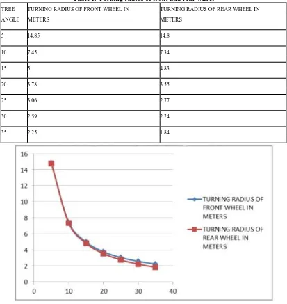
Table I: Turning radius of front and rear wheel
TREE TURNING RADIUS OF FRONT WHEEL IN TURNING RADIUS OF REAR WHEEL IN
ANGLE METERS METERS
5 14.85 14.8
10 7.45 7.34
15 5 4.83
20 3.78 3.55
25 3.06 2.77
30 2.59 2.24
35 2.25 1.84
Fig. 2: Turning radius of front and rear wheel in meters
III 4,5,6DESIGN OF HANDLE BAR
A. Opposing Torque Calculations:
[1]. Opposing Torque:
[2]. Opposing Torque = F*a
F = Rolling Resistive Force a = Moment arm
a= n ∗tanα
n = Trail, α = Steering angle
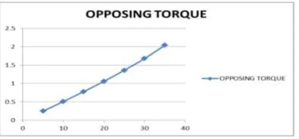
[3]. Various Torques have been obtained for different steering angles a graph is plotted between steering angles and opposing torque.
Fig. 3: Graph for opposing torque
IV REPRESENTATION OF HANDLE BAR
Fig. 4: The handlebar which is introduced in the vehicle to ensure safe and easy handling of the vehicle.
[1]. The handle is designed keeping the handling ergonomics of the vehicle, it is so designed that it does not deflects with the opposing torque acting on it and is also comfortable to the driver to hold the handle hours together.
V 7,8LEAN ANGLE OF THE VEHICLE
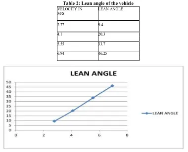
[1]. The angle with which the vehicle must be inclined to the road to negotiate a turn is called lean angle. Various lean angles to negotiate a turn of different radii are plotted on a graph.
[2]. The lean angle is calculated using the formula
β=arctan(v2
R ∗ 2mr +
ML
MLg) M=180 Kg
m=12.5 kg L=0.70627m
Table 2: Lean angle of the vehicle
VELOCITY IN LEAN ANGLE M/S
2.77 9.4
4.1 20.3
5.55 33.7
6.94 46.25
Fig. 5: Graph for lean angle variation
Table 3: Steering parameters and specifications of the vehicle
STEERING PARAMETERS SPECIFICATIONS
Rake angle 280
Trail 165.43mm
Maximum lean Angle (for 25kmph and Radius of curvature = 5 meters)
46.260
Max. Semi-Tree Turning angle 350
Least Turning Radius of Front wheel 2.25 meters Least Turning Radius of Rear wheel 1.84 meters
VI CONCLUSION
[1]. The present work is optimum design and analysis of Steering system for an E-Bike subjected to statistical analysis of Rake, Trial, Tree angles and Wheel turning radii which are used for the design of Handle bar and calculation of Lean angle.
i. The variation of Opposing torque for different Rolling resistive force(F) and Moment arm(a) is shown in the graph(Fig: 3).
ii. The lean angle is calculated using the formula
iii. β = arc tan ( v2
R ∗ 2mr +
ML MLg)
[2]. We have obtained Lean angles for different velocities. We have also drawn a graph showing the variation of Lean angle for different velocities and mass.
REFERENCES
[1]. "Rake & Trail Calculator". RB Racing. Retrieved 2013-12-14.
[2]. Josh Putnam. "Steering Geometry: What is Trail?". Archivedfrom the original on 30 April 2011. Retrieved 2011-04- 07. [3]. "An Introduction to Bicycle Geometry and Handling". C.h.u.n.k. 666. Archived from the original on 30 April 2011. Retrieved
2011-04-07.
[4]. Brown, Sheldon. "Bullmoose Bars". Sheldon Brown. Retrieved 2010-09-16. [5]. Brown, Sheldon."Whatton Bars". Sheldon Brown. Retrieved 2010-06-26.
[6]. "Handlebars for Touring and Commuting". Sheldonbrown.com. Retrieved 2013-10-14.
[7]. Karnopp, D. Vehicle Stability. Marcel Dekker. USA. 2004.
[8]. Watkins, G. K. The Dynamic Stability of Fully Faired Single Track Human Powered Vehicle. Ph.D. Dissertation, The University of North Carolina at Charlotte. 2002