Research of Angle Measurement Technique in
Transponder Landing System
Yihuan Yang
Institute of Telecommunication Engineering, Air Force Engineering University, Xi’an, China Email: yangyihuan-001@163.com
Xiubin Zhao and Jian’an Zhang
Institute of Telecommunication Engineering, Air Force Engineering University, Xi’an, China Email: zhaoxiubin926@163.com, zja929@163.com
Abstract—In this paper, a spatial smoothing technique based on MUSIC algorithm is introduced to substitute the traditional phase interferometer angle measurement algorithm of Transponder Landing System (TLS). It mainly researched the non-uniform linear receiving arrays design scheme under the new algorithm. This proposed algorithm aims to solve the multi-path or multi-targets interference problems of reply signal and eliminate the phase ambiguity caused by receiving arrays’ baseline. It contrasted the feasibility, validity, resolving power and precision of the designed arrays with the uniform arrays in the same condition through computer simulation. The effectiveness and advantage of the proposed algorithm include the usability and reliability of the designed arrays is theoretically investigated. At last, we can obtain the real-time azimuth and elevation information relative to the touchdown point of landing aircraft through coordinate transformation.
Index Terms—Transponder landing system, angle measurement algorithm, arrays design, arrays capability, coordinate transformation
I. INTRODUCTION
To meet the needs of airport in complex site condition and military mobility requirement, ANPC developed Transponder Landing System (TLS) [1, 2] in 1991. TLS obtains the aircraft’s spatial location by measuring the carrier wave phase and TOA of the aircraft’s reply signal, provides the guidance information to approach landing aircraft. It makes up for shortages of the instrument landing system (ILS), such as demanding installation sites or poor mobility. It only asks for ground equipments, using the airborne existing secondary radar equipments and ILS receiving equipment, to provide precision approach landing guidance to the aircraft in complex site
conditions or provisional airports without any changes to the aircraft.
So far, the core journals home and abroad can hardly find the key technology and in-depth research articles about this system. At this point, we start the research of the system’s key technology and correlative issue has the exploration significance to improve the key technology and optimize the performance of the system.
With the gradual opening up of lower space, air traffic capacity increases without cease. Due to great changes of battlefield condition and military field environment, the traditional phase interferometer angle measurement algorithm [3] cannot fully meet the needs of multi-targets resolution, wide range angle measurement, and multi-path interference suppression in harsh environments [4, 5, 6]. According to spatial spectrum estimating theory, these problems can be well solved by using high-precision, super-resolution spatial smoothing technique based on MUSIC algorithm [7, 8, 9, 10].
The spatial smoothing technique and MUSIC algorithm are all based on the principle of array signal processing, and each has a specific requirement for the design of antenna arrays. According to the characteristics of TLS system, it is more reasonable for one-dimensional linear arrays to measure the azimuth and elevation. Combined with the system’s performance, the design scheme and the corresponding performance of TLS antenna arrays were discussed, then, compared them with the uniform arrays in the same condition.
II.TLS ANGLE MEASUREMENT ALGORITHM
To extend the system function and meet the needs of multi-purpose and multi-targets estimation, we can use S mode reply signal [11] shown in Fig. 1 to replace the original 3/A mode replay signal.
The reply data included in the data module follow the 4 replies steering pulses. Every datum is a 1μs “pulse and no-pulse” area. “no-pulse follow a pulse” denotes datum 1, “a pulse follow no-pulse” denotes datum 0.
Manuscript received March 10, 2011; revised August 08, 2011; accepted September 10, 2011.
This work was supported by the Innovative Foundation of AFEU under Grant NO. DYCX1001.
Leader pulse 8.0µs Reply data pulse 56/112µs
BIT1 BIT2 BITN-1 BITN
0 0.51.01.5 3.5 4.5 8.0 9.0
1 0 1 0 1 0 1 0 10
BITN-2
Figure 1. S mode replay signal format
Therefore, the mathematic module of the S mode reply signal can be demonstrated as:
∑
∑
= = − − − + − = 111 / 55 0 2 3 0 ) 2 2 8 ( ) 2 cos( ) ( ) 2 cos( ) ( j c i i c m j t g t f t t g t f t s τ τ π π τ τ (1)wherefcdenotes carrier wave frequency, τdenotes the pulse width, tidenotes the reply signal steering pulse’s time delay. If an denotes the reply signal data sequence,
m
satisfied the equation2:⎩ ⎨ ⎧
= =
= 31,, 10
n n a a
m (2)
The working condition of TLS is comparative poor. Due to topographical conditions and the impact of obstacles near the airport, it will be prone to reflection and scattering phenomena, and also form highly correlated multi-path and direct signals at the receiving arrays. At the same time, the landing aircrafts have the same signal formats. The receiving signals also have high correlation.
In order to improve the accuracy of TLS angle measurement and enhance the system's ability to distinguish multiple targets, we can use the spatial smoothing technique based on Schmidt's MUSIC algorithm to obtain the angle information of the aircraft. The basic principle [12, 13] is as follow:
"
"
) ( 1 t x ) ( 2 t x ) (t xp " ) ( 1t x′ ) ( 1 tx′p− "
) (t x′p
1 2 m−1 m N
Figure 2. TLS angle measurement spatial smoothing principle
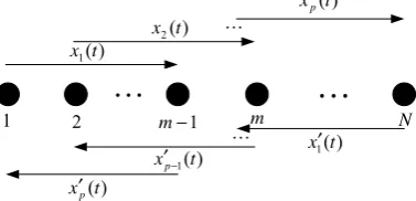
As shown in Fig. 2, if the total number of TLS receiving antenna array element is
N
and receiving signals isP, and P<N, we can divide the Nelements antenna array intopsub-arrays, each sub-array has the same array elements number m−1. For the forwardsmoothing, considering the first array element as the
reference array element of each sub-array, so the k sub-array data model can be demonstrated as:
[
]
) ( ) ( ) ( ) ( ) 1 ( 1 1 t n t s D A x x x t x k k m k k k k + = = − − + + θ "(3)
where, A(θ)=
[
a(θ1),a(θ2),",a(θP)]
is array direction matrix of incident signals, a(θk)isarray steering vector,) (t
s is signal vector, nk(t) is white noise with the zero mean and variance σ2,xk(t)is sub-array output vector.
⎥ ⎥ ⎥ ⎥ ⎥ ⎥ ⎥ ⎦ ⎤ ⎢ ⎢ ⎢ ⎢ ⎢ ⎢ ⎢ ⎣ ⎡ = P d j d j d j e e e D θ λ π θ λ π θ λ π sin 2 sin 2 sin 2 0 0 0 0 0 0 2 1 " # % # # " " (4)
Then the covariance matrix of each sub-array is:
I A D R AD
Rk= (k−1) S( (k−1))H H+σ2 (5)
The mean of all sub-array covariance matrixes is the forward smoothing covariance matrix:
I A D R D p A R p R H p k H k S k p k k f 2 1 ) 1 ( ) 1 ( 1 ) ( ) ( 1 ) ( 1 σ θ θ ⎟⎟ + ⎠ ⎞ ⎜ ⎜ ⎝ ⎛ = =
∑
∑
= − −= (6)
Similarly, the backward smoothing covariance matrix is: I A D R D p A R p R H k m S p k k m p k k p b 2 ) 2 ( * 1 ) 2 ( 1 1 ) ( 1 ) ( 1
σ
θ
θ
⎟⎟ + ⎠ ⎞ ⎜⎜ ⎝ ⎛ = = − + = − + − = − +∑
∑
(7)Then, the forward/backward smoothing covariance matrix can be demonstrated as:
2 b f fb R R
R = + (8)
The characteristic decomposition [14] of covariance matrix fb
R is:
H N N N H S S S
fb U U U U
R = Σ + Σ (9)
To the characteristic decomposition of fb
R , there are Plarge eigenvalues and corresponding eigenvectors form the signal subspace US and m−1−Psmall eigenvalues and corresponding eigenvectors form the noise subspace
UN, and both orthogonal to each other. The MUSIC spatial spectrum of the reply signals can be demonstrated as: ) ( ) ( 1 ) ( θ θ θ a U U a P H N N H
Making spectrum peak searching to equation (10), the peaks correspond to the angles are the azimuths or elevations of the landing aircrafts.
III. TLS ANTENNA ARRAYS DESIGN
To avoid the impact of phase ambiguity [15, 16], DOA estimation technique always adopts uniform equidistant arrays whose baseline is shorter than half wavelength. Actually, due to limitation of spatial location and arrays coupling, non-uniform arrays whose baseline is longer than half wavelength is more available. But, impact of phase ambiguity must be eliminated.
When set the array, assuming array element position is of 0.5λunits, and the array element position vector is X =
(
x1,x2"xN)
, so X =0.5λ[
n1,n2,"nN]
, consideringn1 as the reference point (n1=0), ni is non-negative integer and ni>N−1[17].According to the definition of the steering vector, if the arrays are ambiguity, so has the equation (11):
i n i
n j x
x j
e
e λ θ
π θ
λπ − ′
−
= sin
2 sin
2
i i θ
θ ≠ ′ (11) Making the logarithm to equation (11):
(
i i)
ii k
n sinθ −sinθ′ =2 (12) Where,ki,
n
iare corresponding positive integer. Ifi
i θ
θ
ρ =sin −sin ′, equation (12) can be rewritten as:
i i
n k
2 =
ρ i=2,3,",M (13)
Because the linear array’s angle measurement range is 0
90
− ~90 , so0 ρ <2,ki<ni, for eachni, the equation (14) can exit.
⎪⎭ ⎪ ⎬ ⎫
⎪⎩ ⎪ ⎨ ⎧
− ± =
j i
ij ij
n n
k 2 , 0
ρ kij < ni −nj ,
i
≠
j
(14)If
n
i,n
jare prime numbers, the equation (15) can exit.{
12∩ 23∩ ∩ 1,}
={ }
0= ρ ρ ρM− M
ρ " (15)
That is to say, if ni, njare prime numbers, parameter
ρ has only 0 element satisfied equation (15), so
asθi =θi′, the array has no ambiguity.
According to literature [18, 19], we can design the arrays like this:
Assuming the arrays Φi=
{
d1,d2"dq−1}
is theisub-array which constitutes the entire TLS receiving antenna arrays ,i=1,2,"[
(N−1) (q−1)]
,[ ]
• is integer operation. Then the TLS receiving arrays can be demonstrated as:{
Φ1,Φ2,"Φ[(N−1)/(q−1)],d1,d2,"dj}
=
Φ (16)
where, d1,d2"dq−1 denotes the length of each sub-array’s baseline, and they are mutual primes to each other, j=(N−1)modp, pis the number of sub-array elements, N is the number of TLS receiving array element.
To ensure the simple, mobility and flexibility of the system, considering to the system’s accuracy, we can respectively use one-dimensional non-uniform linear arrays with 2 sub-arrays and 6 total array elements and one-dimensional non-uniform linear arrays with 2 sub-arrays and 8 total array elements to denote the azimuth receiving antenna arrays and the elevation receiving antenna arrays. So the receiving antenna arrays can be demonstrated as:
{
1 2 d1}
AZ = Φ Φ
Φ (16)
{
1 2 3 d1}
EL = Φ Φ Φ
Φ
(17)
Ifd1=3,d2 =2, array (16, 17) can be written as:
{
3 2 3 2 3}
=
ΦAZ (18)
{
3 2 3 2 3 2 3}
=
ΦEL (19)
The sensor position vector is:
[
0 3 5 8 10 13]
5 . 0 λ
=
AZ
X (20)
[
0 3 5 8 10 13 15 18]
5 . 0 λ =
EL
X
(21)
To reduce the computing complexity and difficulty of project implementation, we can only use the method of inserting 0 elements [20, 21, 22] to transform the non-uniform array (20, 21) into a uniform array to better satisfy the TLS angle measurement algorithm. So the
6
=
N non-uniform arrays will be transformed into the N′=14 virtual non-uniform arrays and the
8
=
N non-uniform arrays will be transformed into the N′=19 virtual non-uniform arrays. Then using spatial smoothing to the new virtual non-uniform arrays can realize the function of high-precision angle measurement. The array models are shown in Fig.3 and Fig.4:
Figure 3. TLS virtual arrays spatial smoothing model (Azimuth)
) (
1 t
xf
) (
2 t
xf
) (
1 t
xb
) (
2t
xb
Real Array Element Virtual Array Element
The new array steering vector AZ( k) TLS
a θ and
) ( k EL TLS
a θ are:
T j j j j j k AZ TLS k k k k k e e e e e a ] , 0 , 0 , , 0 , , 0 , 0 , , 0 , , 0 , 0 , 1 [ ) ( 13 10 8 5 3 β β β β β θ − − − − −
= (22)
T j j j j j j j k EL TLS k k k k k k k e e e e e e e a ] , 0 , 0 , , 0 , , 0 , 0 , , 0 , , 0 , 0 , , 0 , , 0 , 0 , 1 [ ) ( 18 15 13 10 8 5 3 β β β β β β β θ − − − − − − − = (23) where λ θ π β k k dsin 2
= , k=1,2,",P. The location of
the virtual array element is with “0” compensation. According to Fig.3 and Fig.4, we could firstly use forward/backward spatial smoothing algorithm to the two 9 elements sub-arrays and the two 14 elements sub-arrays respectively. Then the new covariance matrix
fb AZ TLS
R _ and RTLSfb _ELcan be obtained by taking the new
array steering vector AZ( k) TLS
a θ and aTLSEL (θk)into equation (6, 7, 8). At last, the MUSIC spectrum will display the angles of the aircrafts.
In order to investigate the feasibility of the designed arrays, assumed that there were three aircrafts in close proximity at 5°, 9°, 14° azimuth directions, and the elevation directions were 3°, 6°, 8°, SNR = 10dB, the snapshots was 640. The azimuth and elevation angle estimating results of TLS arrays and ULA with same array element were shown in Fig.5 and Fig.6:
-40 -30 -20 -10 0 10 20 30 40 -50 -45 -40 -35 -30 -25 -20 -15 -10 -5 0 (
Space Angle/ o)
N or m al iz ed M U S IC S pe c tr um /( dB ) ULA TLS Arrays
Figure 5. Angle spectrum of different array models (Azimuth)
-5 -2 1 4 7 10 13 15
-60 -50 -40 -30 -20 -10 0 (
Space Angle/ o)
N o rm al iz ed M U S IC S pec tr um /( dB ) ULA TLS Arrays
Figure 6. Angle spectrum of different array models (Elevation)
According to Fig.5 and Fig.6, when the aircrafts are in close proximity, TLS arrays can clearly distinguish the azimuth and elevation angles of the aircrafts, while the ULA with same array element can not accurately distinguish the azimuth and elevation angles of the aircrafts. It also shows the feasibility of the designed TLS arrays.
To investigate the effectiveness of multi-targets estimating of TLS arrays: assumed that the azimuth angles of two targets were 10° and 15°, the elevation angles of the two targets were 3° and 6° , the snapshots was 640, set the successful estimation threshold according to TLS accuracy, make 1000 times Monte Carlo experiments on each SNR. The angle estimation successful probabilities of TLS arrays and ULA with the same array element were shown in Fig.7, Fig.8, Fig.9 and Fig.10:
-5 0 5 10 15 20
0 0.1 0.2 0.3 0.4 0.5 0.6 0.7 0.8 0.9 1 SNR/(dB) S uc c es s ful P robab ility ( ) Target1 10° ( ) Target2 15°
Figure 7. Successful probability of TLS arrays (Azimuth)
-5 0 5 10 15 20
0 0.1 0.2 0.3 0.4 0.5 0.6 0.7 0.8 0.9 1 SNR/(dB) S u c c e s s fu l P ro b a b ility ( ) Target1 10° ( ) Target2 15°
Figure 8. Successful probability of ULA (Azimuth)
-5 0 5 10 15 20
0 0.1 0.2 0.3 0.4 0.5 0.6 0.7 0.8 0.9 1 SNR/(dB) S u c c e s s fu l P ro b a b ilit y ( ) Target1 3° ( ) Target2 6°
-5 0 5 10 15 20 0
0.1 0.2 0.3 0.4 0.5 0.6 0.7 0.8 0.9 1
SNR/(dB)
S
uc
c
es
s
ful
P
robabi
lit
y
( )
Target1 3°
( )
Target2 6°
Figure 10. Successful probability of ULA (Elevation)
According to simulations from Fig.7 to Fig.10, we can see that the angle estimation effectiveness of TLS arrays is stronger than the uniform arrays with the same array element for multi-targets estimation; it fatherly validated the feasibility of the designed TLS arrays even at a lower SNR.
IV. PERFORMANCES OF TLS ANTENNA ARRAYS
The performances of TLS arrays are mainly scaled by the resolving power, the angle measurement error and mean square error of the antenna arrays.
Array resolution mainly investigates the ability to distinguish two close signals or targets. In the TLS working environment, TLS receiving antenna arrays must need high array resolution because of the requirements of multi-path effects or the approaching of multiple aircrafts at the same time.
If P(θ) a (θ)USUSHa(θ) H
= is signal spectrum, make
the following definitions:
2 ) ( ) (θ1 Pθ2 P
Ppezk = + (24)
2 2
1 θ
θ
θm= + (25)
) ( )
( Ppeak P m
QΔ = − θ (26)
whereΔ=θ1−θ2, ifQ(Δ)>0, Q(Δ)is distinguished.Δ is the array resolution, smaller Δ means higher resolution.
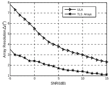
According to the definition of array resolution, make 1000 times Monte Carlo experiments on each SNR to TLS arrays and ULA with the same array element. The relationship between array resolution and SNR were shown in Fig. 11 and Fig.12. We can clearly see that TLS array resolution is better than ULA with the same array element. At the same time, it reveals that the designed TLS receiving antenna arrays can be better used for precision angle measurement and multi-targets resolution in complex environment theoretically.
-5 0 5 10 15 1
2 3 4 5 6 7 8 9
SNR/(dB)
△
A
rray
R
e
s
o
lu
ti
o
n
/(
o)
ULA TLS Arrays
Figure 11. Array resolution of different array models (Azimuth)
-5 0 5 10 15 1
2 3 4 5 6 7 8
SNR/(dB)
△
A
rr
ay
R
e
s
o
lu
ti
o
n
/(
o)
ULA TLS Arrays
Figure 12. Array resolution of different array models (Elevation)
The error and mean square error mainly appraise the accuracy and stability of the receiving antenna arrays. Typically, the angle corresponding to the spatial spectrum peak is not the aircraft real angleθ, but the maximum likelihood estimation angleθˆ . To a certain array model,
angle measurement accuracy can be appraised by the angle measurement error γ and the mean square errorRMSEas the following equations:
θ θ
γ = i −
i ˆ (27)
∑
=
=
L
i i L RMSE
1 2 1 )
(θ γ (28)
where θˆi
is the estimated angle at the i time, γi is angle estimation error, Lis estimation times.
-5 0 5 10 15 20 0
0.1 0.2 0.3 0.4 0.5 0.6
SNR/(dB)
A
n
gle E
R
R
O
R
and
R
M
S
E
/(
o)
( ) Target1-ERROR 10°
( ) Target2-ERROR 15°
( ) Target1-RMSE 10°
( ) Target2-RMSE 15°
Figure 13. TLS arrays angle estimating accuracy (Azimuth)
-5 0 5 10 15 20 0
0.5 1 1.5 2 2.5 3 3.5
SNR/(dB)
A
ngle E
R
R
O
R
an
d R
M
S
E
/(
o)
( ) Target1-ERROR 10°
( ) Target2-ERROR 15°
( ) Target1-RMSE 10°
( ) Target2-RMSE 15°
Figure 14. ULA angle estimating accuracy (Azimuth)
-5 0 5 10 15 20 0
0.05 0.1 0.15 0.2 0.25 0.3 0.35
SNR/(dB)
A
ngle E
R
R
O
R
and R
M
S
E
/(
o)
( ) Target1-ERROR 3°
( ) Target2-ERROR 6°
( ) Target1-RMSE 3°
( ) Target2-RMSE 6°
Figure 15. TLS arrays angle estimating accuracy (Elevation)
-5 0 5 10 15 20 0
0.5 1 1.5 2 2.5 3
SNR/(dB)
A
ngle E
R
R
O
R
an
d R
M
S
E
/(
o)
( ) Target1-ERROR 3°
( ) Target2-ERROR 6°
( ) Target1-RMSE 3°
( ) Target2-RMSE 6°
Figure 16. ULA angle estimating accuracy (Elevation)
According to the simulations from Fig.13 to Fig.16, we can clearly see that the designed TLS receiving antenna arrays have higher estimation accuracy and better effect for multi-targets estimation, and the estimation accuracy has no relationship with the targets angles. It can also carry out the correct angle estimation even at a lower SNR and provide a good theoretical basis to design or realize the system.
V. COORDINATE TRANSFORMATION
Measurements of angles and range are derived from signals received by the designed TLS antenna arrays respectively. However, during the period of approaching, the aircraft’s position information provided by ground equipment must base on the touchdown point as origin. So, the aircraft’s available location data can only be derived after coordinate transformation of the measured information.
Figure17.Geometry relationship between the aircraft’s position and
measurements
[23]. Assumed that the phase centers of azimuth antenna arrays and elevation antenna arrays are (XA,YA,ZA)and
) , ,
(XE YE ZE respectively. The position of approaching aircraft is(XT,YT,ZT).
Based on Fig.17, the aircraft’s position equation can be obtained by: ⎪ ⎪ ⎪ ⎪ ⎩ ⎪⎪ ⎪ ⎪ ⎨ ⎧ − = − − − = − − − = E E T A T A A T A T A A T R Z Z Z Z R X X Z Z R Y Y ϕ θ θ sin ) ( cos ) ( sin 2 2 2 2
(29)
where θ , ϕ denotes the azimuth and elevation measurement respectively; θ0 , ϕ0 denotes the azimuth and elevation relatives to the touchdown point;
A
R , REwhich can be obtained by ask/answer range measurement algorithm [24] denotes the distance from azimuth antenna arrays and elevation antenna arrays to the approaching aircraft respectively.
Equation (29) can also be expressed as:
⎪ ⎪ ⎩ ⎪⎪ ⎨ ⎧ + − − + = + − − + = + = θ ϕ θ ϕ ϕ sin ) sin ( cos ) sin ( sin 2 2 2 2 E A E A A T E A E A A T E E T R Z Z R Y Y R Z Z R X X R Z Z
(30)
So, we can simply obtain the aircraft’s angles relative to touchdown according to the geometry relationship in Fig.17: Azimuth: θ ϕ θ ϕ θ cos ) sin ( sin ) sin ( arctan arctan 2 2 2 2 0 E A E A A E A E A A T T R Z Z R X R Z Z R Y X Y + − − + + − − + = = (31) Elevation: 2 2 2 2 2 2 2 2 0 ) sin ( ) cos ( sin arctan arctan θ θ ϕ ϕ R R Y R R X R Z Y X Z A A A A E E T T T − + + − + + = + = (32)
where R=ZE −ZA+REsinϕ
.
The objective of coordinate transformation is to utilize the measured azimuthθ, elevationϕ and rangRA,REof real time to update the aircraft’s real-time spatial location coordinate bases on those equations above.
VI. CONCLUSION
The paper simply introduced the traditional TLS angle measurement principle. According to the requirement of current actual military and civilian airport environment, it used spatial smoothing technique based on MUSIC algorithm to substitute the traditional angle measurement algorithm of TLS. The new angle measurement algorithm
was briefly introduced, but the TLS receiving antenna arrays scheme was mainly designed. Then, the paper analyzed the feasibility, effectiveness, array resolution and accuracy of the designed TLS receiving antenna arrays and the ULA in the same condition through computer simulation. It strongly validated the availability and reliability of the designed TLS receiving antenna arrays based on the new angle measurement algorithm. At last, the paper carried out the aircraft’s real-time position through coordinate transformation with the measured azimuth, elevation and rang of real time. It also provided the theoretical foundation to design and realize the whole system.
REFERENCES
[1] Xiang Dong Yu. “Transponder landing system suitable for complex terrain airport,” International aviation magazine, vol. 9, pp. 52-53, September 2004.
[2] Karl Winner, “Application of the Transponder Landing System to Achieve Airport Accessibility,” http:// www.ANPC.com, October 2010.
[3] Qin Lu, Qian Jun Ding, Hui Chen, Fang Jing Han, “The performance research of the MUSIC and the phase interferometer algorithm,” Information technology, vol.8, pp.9-12, August 2010.
[4] C. Y. Qi, Y. S. Zhang, Y. Han, and X. H. Chen, “An algorithm on high resolution DOA estimation with unknown number of signal sources,” In Proc. 4th Int. Conf. Microw. Millimeter Wave Technol. (ICMMT), Aug. 18-21, 2004, pp. 227-230.
[5] R. Kumaresan and D. W. Tufts, “Estimating the angles of arrival of multiple aircraft waves,” IEEE Trans. Aerosp. Electron. Syst., vol. 19, pp. 134-139, January 1983. [6] B. P. Ng, “A MUSIC approach for estimation of directions
of arrival of multiple narrowband and broadband sources,” IEEE Signal Process. vol.40, pp. 319-323, August 1994. [7] B. Friedlander and A. J. Weiss, “Direction finding in the
presence of mutual coupling,” IEEE Trans. Antennas Propag., vol. 39, pp.273-284, March 1991.
[8] Ying Zhang, Boon Poh Ng, “MUSIC-Like DOA Estimation without Estimating the Number of Sources,” IEEE Trans. Signal Process., vol. 58, pp.1668-1676, March 2010.
[9] Chambers C, Tozer T C, Sharman K C and Durrani T S. “Temporal and spatial sampling influence on estimates of superimposed narrowband signals: when less can mean more.” IEEE Trans. Signal Process, vol.44, pp. 3085-3098, December 1996.
[10]Chao Wei Li, Xiao Ping Zhou, Jun Yang, “A Method of Target Distinction and Tracking Based on MUSIC Algorithm,” electronic information counters technology, vol.25, pp.6-8, May 2010.
[11]Wei Zhang, Yan Xiang Xu. Principle of Secondary Surveillance Radar, Beijing: National Defense Industry Press, 2009, pp.140-144.
[12]Scmidt R O. “Multiple emitter location and signal parameter estimation,” IEEE Trans. on AP, vol.34, pp.276-280, March 1986.
[13]Xian Da Zhang. Modern Signal Processing, 2nd ed., Beijing: Tsinghua University Press, 2002, pp.126-137. [14]A. Samir and A. M. Karim, “A fast algorithm for the
[15]K. C. Tan, S. S. Goh, and E. C. Tan, “A study of the rank -ambiguity issues in direction-of-arrival estimation,” IEEE Trans. Signal Process., vol.44, pp. 880-887, April 1996. [16]Xiang Yi Gong, Jun Quan Yuan, Ling Hua Su. “Based on
multi-phase interferometer array of solutions to DOA estimation ambiguity algorithm,” Electronics and Information Technology, vol.28, pp. 55-59, January 2006. [17]Proukakis C, Manikas A. “Study of ambiguities of linear
arrays,” In Proc. ICASSP, Adelaide, Australia, April 1994, pp.549-552
[18]Yong Liang Wang. Spatial Spectral Estimation Theory and algorithm, Beijing: Tsinghua University Press, 2004, pp.355-373.
[19]T. T. Zhang, Y. L. Lu, and H. T. Hui, “Compensation for the mutual coupling effect in uniform circular arrays for 2D DOA estimations using a new searching algorithm,” IEEE Trans. Aerosp. Electron. Sys., vol. 44, pp. 1215- 1221, July 2008.
[20]De Shu Liu, Jing Qing Luo, Jian Yun Zhang. Spatial spectrum estimation and application, Hefei: Chinese Science and Technology Press, 1997, pp.171-173.
[21]Qiang Guo, Jie Gu, Guo Qing Zhao, “A new non-uniform linear array interpolation finding algorithm,” Chinese Institute of Electronics, vol.4, pp.324-327, January 2006. [22]Xi Tuo Zhang, Wei Rao, Dong Mei Hu, Qiang Liu, “DOA
Estimation based on Non-uniform Linear Array and Modified MUSIC Algorithm,”Fire Control and Command ControlVol.34, pp.35-40, Supplement, June 2009.
[23]Jin Lu He. “Coordinate transformation, coordinate transformation algorithm and mathematic models of MMLS,” MMLS Thesis Collection of Xi’an Navigation Graduate School, 1999, pp.105-115.
[24]Xiao Hua Tian, Yi Jian Zhou, Theory and technology of wireless location, Beijing: National Defense Industry Press, 2010, pp.140-141.
Yihuan Yang was born in Sichuan, china
in 1987. He received the bachelor's degree in navigation engineering from Air Force Engineering University, Xi’an, China in 2009. He began pursuing the M.S. degree in communications and information system from the Institute of Telecommunication Engineering, Air Force Engineering University since 2009. His research interests include radio navigation and navigation signal processing.
Xiubin Zhao (M’93) received the M.S.
degree in electrical information engineering from Nanjing University of Aeronautics and Astronautics, Nanjing, China, in 1996, the Ph.D. degrees in signal and information processing from the Xibei Industry University, Xi’an, China, in 2000.
He has been engaged in basic theory research and technology innovation of radio navigation since 1990. He was recruited as senior member of Chinese Institute of Electronics in 2000, employed as Electronic Journal reviewer in 2001, recruited as the National Science Foundation reviewer in 2003, recruited as Institute of Electronics Radar and Navigation professional member of Shanxi Province in 2005.
His research interests include radio navigation, navigation signal processing, satellite location technology and simulation technology. Prof. Zhao engaged in navigation work. He has published more than 50 articles on domestic or international core journals. His teaching material “Aeronautical Radio Navigation System”, “Navigation New Materials and Technology” were published by the electronics industry publishing company.
Jian’an Zhang was born in Gansu,