S IJENS © April 2014 IJEN
-ME IJM -7474 -02 103 14
Design a Robust PID Controller of an Active
Suspension System
Dr. Hayder Sabah Abd AL-Amir And Assistant Lecturer. Ali Talib Abd Al Zahra
Abstract-- The objective of control of the suspension system is to
improve the ride comfort and road holding ability under different road conditions. The main contribution in this paper is to present a method, to design a robust control strategy in an active suspension system for one-quarter car model. The methodology for calculation the control gains by making a PID as a function of mass and velocity vehicle. The robust PID controller is tested at different road profiles (bumps). Good results for robust PID controller against passive system, the average reduction in peak overshoot for all road types that taken
were % . The performance of robust and unrobust PID 87
controller in active suspension was compared. Finally, it means that robust PID controller is the best for active suspension system.
Index Term-- quarter car model, active suspension system, robust PID controller.
I. INTRODUCTION
All of vehicles moving on the different profiles road are exposed to vibrations which are harmful both for the passengers in terms of comfort and for the durability of the vehicle itself. Therefore the main task of a vehicle suspension is to ensure ride comfort and road holding for a variety of road conditions. Any suspension system in the vehicle must be soft against road disturbances and hard against load disturbances. A Basic automobile suspension that is known as a passive suspension system consists of an energy storing element normally a spring and an energy dissipating element normally a shock absorber. The main weakness of the passive suspension is that it is unable to improve both ride comfort and safety factor simultaneously. In the passive suspension system, there is always trade-off between vehicle ride comfort and safety factor [1]. To improve the ride comfort, the safety factor must be sacrificed, and vice versa. One way to overcome such a problem, the car suspension system must be controlled.
Active suspension systems use actuator; an actuator (linear motor, hydraulic cylinder, etc.) parallel to the suspension systems is placed between the wheel and the vehicle body. When designing an active suspension, two important issues must be considered: the possible failure of the external energy source, and the transfer of a large quantity of mechanical energy in a structure that has the potential to destabilize the controlled system. However, the active suspension systems significantly improve car comfort, handling performance and driving safety, realizing an
improved compromise among different vibrations modes of the vehicle (bounce, roll, pitch).
In recent years, a great number of studies have been engaged in the research about the control of suspension field. Optimal control has been used in active suspension system since 1960s [2]. Most design methods for automotive active suspension systems are based on optimal control [3, 4, 5, 6]. The fuzzy logical control has emerged another method for design of automotive active suspension system [7, 8, 9, 10, 11].
Application of active suspension controller by the LQR and PID controllers are still using widely for linear suspension model because they are relatively easily in structure and tune. The performance of the linear controllers, become unrobust when the parameters of the system are changing and so they need re-tune its gains.
In this paper an attempt is made to develop an active suspension with robust PID controller to improve the performance of suspension system. The gains of the PID controller are made as a function of mass and frequency of excitation of the road profile (which depends on vehicle velocity) to avoid the unrobust of PID controller when the mass and velocity are changing. The present controllers is test against different types of road profile (bumps) and different values of the mass and the velocity of the vehicle while the published works, test their suggested controllers at certain road profile and constant value of the mass and the velocity
I. ACTIVE SUSPENSION MODEL
S IJENS © April 2014 IJEN
-ME IJM -7474 -02 103 14
The equations of motion of active suspension system are:
0 ) 2 ( 2 ) 1 2 ( 1 2 .. 0 ) 2 1 ( 1 ) 2 . 1 . ( 1 .. F w x k x x k w M x F x x k x x c b M x ……….… (1)The state variables and the parameters are defined in Appendix (A)
II. ROBUST PID CONTROLLER DESIGN
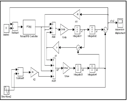
The task of the controller in active suspension system (Figure (2)) is to minimize the difference between the body and tire displacements to give the passengers in the vehicle more comfort against the road disturbance.
The PID controller, a kind of linear controller, which include three controlled variable, proportion (P), integral(I) and differential (D) through linear combination. Its control law is:
dtt t de D K t t e I K t e P K
F ()
0 () )
(
………..…(2)
Where, Kp is proportional coefficient, KI is integral time constant, KDis differential time constant.
The value of PID gains must be tuned at certain values of model parameters. The Ziegler – Nichols tuning rules are used to determine gains of PID controller [12]. The values of the PID gains which correspond to the mass and the velocity are shown in Appendix (B).
When the parameters of the model are changing, the performance of PID controller will be unrobust and the error steady state will increase.
In the present work the gains of PID controller are made as function of mass and velocity of vehicle as shown in equation (3). 3 iV 2 V b hM V 2 b gM 2 fV V b eM 2 b dM cV b bM a D I, P, K ……….… (3)
Where a, b, c,…,i. are constants and its value are found from fitting data of gains , mass and velocity. Table (1) shows the values of the contents. The variation of controller gains with mass and velocity of the vehicle are shown in figure (3) Therefore the present PID controller is designed to be more sensitive to road profile changing and can give a good performance comparing with that PID controller having constant gains.
Table I
The values of the contents of the equation (3) Kd Ki Kp -5.101E4 -4.25E6 1.4214E3 a 388.9 3.092E4 -8.645 b 4429 4.513E5 24.92 c -0.5526 -31.8 -44.53 d -24.7 -2485 -63.44 e -3.87 -359.8 15.56 f 0.0379 2.93 15.5 g -0.013 8.1 -22.7 h 0.0210 -31.9 -28.16 i
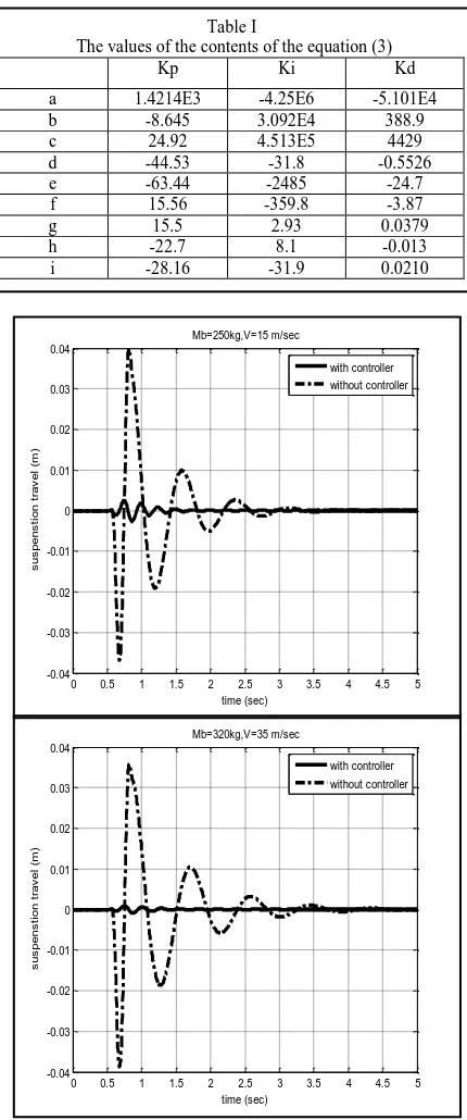
Fig. 5. Time response of the suspension system with and without controller; road input type-a.
0 0.5 1 1.5 2 2.5 3 3.5 4 4.5 5
-0.04 -0.03 -0.02 -0.01 0 0.01 0.02 0.03 0.04 s u s p e n s ti o n t ra v e l (m ) time (sec) Mb=320kg,V=35 m/sec with controller without controller
0 0.5 1 1.5 2 2.5 3 3.5 4 4.5 5
-0.04 -0.03 -0.02 -0.01 0 0.01 0.02 0.03 0.04 s u s p e n s ti o n t ra v e l (m ) time (sec) Mb=250kg,V=15 m/sec with controller without controller
Fig. 1. Quarter vehicle model of active suspension
S IJENS © April 2014 IJEN
-ME IJM -7474 -02 103 14
III. SIMULATION AND DISCUSSION
The proposed Robust PID controller model for active suspension system is verified with computer simulation using Matlab program. Time-domain analyses show the performance of passive (without controller) and active suspension system using robust PID controller. The present controller is test against different types of road profile (bumps) which are shown in figure (4).
a-for the road profile type a in figure (4)
Figure (5) shows the time responses of the suspension system with and without controller. The responses are performed at two condition Mb=250 kg, V=15 m/sec and Mb=320 kg, V=35 m/sec respectively.
It can be easily seen that active suspension significantly reduces suspension travel (the car body displacement and tire deflection) and settling time more than passive suspension.
For the first condition, the peak overshoot of suspension travel for passive system is 0.04 m and settling time at 1.5 sec. While for the active suspension system it is 0.0045 m and settling time at 3.5 sec. The reduction in peak value = (passive value – active value) / passive value = 88.75 %.
While the reduction in peak value for second condition is 95.7 %.
It is clear that the increasing in the mass and speed of the vehicle give better suspension system performance.
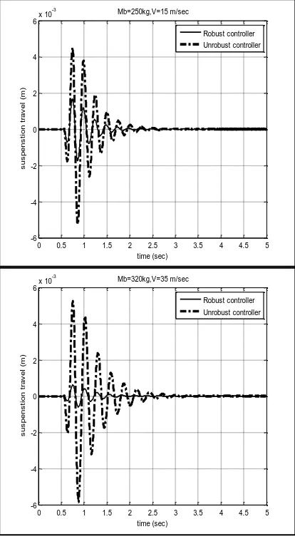
Figure (6) explains that the robust system is better than the unrobust system in term of peak overshoot. The reduction ratio in peak value for first condition is 52%, while for second condition is 90%.
b-for the road profile type-b in figure (3)
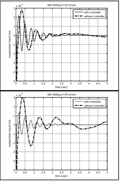
Here, the road profile is presented as sine wave. Figure (6) shows the time responses of the suspension system with and without controller.
The responses are performed at two condition Mb=350 kg, V=20 m/sec and Mb=250 kg, V=15 m/sec respectively Fig. 2. Robust PID controller model for active suspension
system
0 0.2 0.4 0.6 0.8 1 1.2 1.4 1.6 1.8 2 0
0.005 0.01 0.015 0.02 0.025 0.03 0.035 0.04 0.045 0.05
time (sec)
b
u
m
p
h
e
i
g
h
t
(
m
)
0 1 2 3 4 5 6 7 8 9 10 -0.04
-0.03 -0.02 -0.01 0 0.01 0.02 0.03 0.04
b
u
m
p
h
e
ig
h
t
(
m
)
time (sec) 0 1 2 3 4 5 6 7 8 9 10
0 0.001 0.002 0.003 0.004 0.005 0.006 0.007 0.008 0.009 0.01
time (sec)
b
u
m
p
h
e
ig
h
t
(
m
)
Type-a Type-b Type-c Fig. 4. road profile types
S IJENS © April 2014 IJEN
-ME IJM -7474 -02 103 14
In Figure (7) we can see clearly that activity of robust PID controller to handle the disturbance as in this situation. For the second condition the maximum overshoot in active suspension system is 0.0013 m and reached to settling time at 3 sec. While for the passive system it is 0.003 m and transient continuously, the reduction ratio in peak value is 56%.
Fig. 6. Time response of the suspension system with robust controller and unrobust controller; road input type-a.
0 0.5 1 1.5 2 2.5 3 3.5 4 4.5 5
-6 -4 -2 0 2 4 6x 10
-3
s
u
s
p
e
n
s
ti
o
n
t
ra
v
e
l
(m
)
time (sec) Mb=250kg,V=15 m/sec
Robust controller Unrobust controller
0 0.5 1 1.5 2 2.5 3 3.5 4 4.5 5
-6 -4 -2 0 2 4 6x 10
-3
s
u
s
p
e
n
s
ti
o
n
t
ra
v
e
l
(m
)
time (sec) Mb=320kg,V=35 m/sec
Robust controller Unrobust controller
Fig. 8. Time response of the suspension system with and without controller; road input type-c.
0 0.5 1 1.5 2 2.5 3 3.5 4 4.5 5 -0.08
-0.06 -0.04 -0.02 0 0.02 0.04 0.06
s
u
s
p
e
n
s
ti
o
n
t
ra
v
e
l
(m
)
time (sec) Mb=250kg,V=10 m/sec
with controller without controller
0 0.5 1 1.5 2 2.5 3 3.5 4 4.5 5 -0.08
-0.06 -0.04 -0.02 0 0.02 0.04 0.06
s
u
s
p
e
n
s
ti
o
n
t
ra
v
e
l
(m
)
time (sec) Mb=350kg,V=15 m/sec
S IJENS © April 2014 IJEN
-ME IJM -7474 -02 103 14
c-for random road profile type-c in figure (3)
Figure (8) shows the time responses of the suspension system with and without controller. The responses are performed at two conditions
Mb=250 kg, V=10 m/sec and Mb=350 kg, V=15 m/sec respectively.
From figure (8) it can be seen that the robust PID controller gives enhancement of system stability and performance by trying to suppress this motion resulting from random profile.
IV. CONCLUSIONS
The dynamic behavior of a vehicle is heavily influenced by changing of the vehicle parameters. Therefore; the performance of any controller may become unrobust and unstable during the work. In this paper, the gains of the PID controller are made as function of vehicle speed and vehicle mass to improve the suspension response for vehicle and make the controller more robust.
The results of the robust PID controller simulations give acceptable responses for suspension travel for different vehicle condition and different types of road until in difficult condition in comparing with passive suspension system. The reduction in peak overshoot and settling time of responses are achieved. This behavior improves the ride comfort and road holding ability of the vehicle.
V. REFERENCES
[1] D. Hanafi "PID Controller Design for Semi-Active Car Suspension Based on Model from Intelligent System Identification" d International Conference on Computer Engineering and Applications, 2010.
[2] D. Hrovat, Application of optimal control to advanced automotive suspension design, Transactions of ACME, Journal of Dynamic system, Measurement and control, Vol. 115, pp. 328-342, 1993.
[3] A. G. Thompson, Optimal and suboptimal linear suspension for road vehicle, Vehicle System Dynamic, Vol. 13, No. 12, pp. 61-72 , 1984.
[4] J. H. Li and T. H. S. Li, Optimal output feedback stabilization of active suspension control using acceleration measurement, Journal of IEEE. IECON'95, Orlando, FL, pp. 1100-1111, 1995.
[5] M. A. Salman, A. Y. Lee and N. M. Boustany, Reduced order design of active suspension control, Journal of IEEE, pp. 1038-1043, 1988.
[6] D. Hrovat, Optimal active suspension structures for quarter car vehicle models, Automatica, Vol. 26, No. 5, pp. 845-860, 1990. [7] M. V. C. Rao and V. Prahald, A tunable fuzzy logic controller for vehicle active suspension systems, Fuzzy set Syst., Vol. 85, No. 1, pp. 11-21, 1997.
[8] Yahaya Md. Sam and Johari Halim Shah Bin Osman, Modeling and control of active suspension system using proportional integral sliding mode approach, Asian journal of control, Vol. 7, No. 2, PP. 91-98, 2005.
[9] R. K. Pekgokgoz, M. A. Gurel, M. Bilgehan and M. Kisa, Active suspension of cars using fuzzy logic controller optimized by genetic algorithm, International journal of engineering and applied sciences, Vol. 2, Issue 4, PP. 27-37, 2010.
[10] Nemat Changizi and Modjtaba Rouhani, Comparing PID and fuzzy logic control a quarter car suspension system, The journal of mathematics and computer science, Vol. 2, No. 3, PP. 559-564, 2011.
[11] Sayel M. Fayyad, Constructing control system for active suspension system, contemporary engineering sciences, Vol. 5, No. 4, PP. 189-200, 2012.
[12] Ogata,”Modern Control Engineering”,Prentice-Hall International Editions,2004.
Appendix (A) Table II
Vehicle variables and parameters
Symbol Description Value Unit
c1 Suspension damper coefficient 1000 Ns/m
F Actuator force - N
k1 Spring stiffness 18600 N/m
k2 Tire spring stiffness 196000 N/m
KD Differential time constant. -
KI Integral time constant -
Kp Proportional coefficient -
Mb Quarter car sprung mass 250-350 kg
Mw Unsprung mass 50 kg
V Vehicle velocity 10-40 m/s
x1 Sprung mass vertical displacement - m
x2 Unsprung mass vertical displacement - m
w Road profile - m
Fig. 7. Time response of the suspension system with and without controller; road input type-b.
0 0.5 1 1.5 2 2.5 3 3.5 4 4.5 5 -5
-4 -3 -2 -1 0 1 2 3x 10
-3
s
u
s
p
e
n
s
ti
o
n
t
ra
v
e
l
(m
)
time (sec) Mb=250kg,V=15 m/sec
with controller without controller
0 0.5 1 1.5 2 2.5 3 3.5 4 4.5 5 -5
-4 -3 -2 -1 0 1 2 3x 10
-3
time (sec)
s
u
s
p
e
n
s
ti
o
n
t
ra
v
e
l
(m
)
Mb=350kg,V=20 m/sec
S IJENS © April 2014 IJEN
-ME IJM -7474 -02 103 14
Appendix(B) Table III
Values of the PID gains which correspond to the values of the mass and the velocity of the vehicle.
Mb (kg) V (m/sec.) KP KI KD