ISSN (e): 2250-3021, ISSN (p): 2278-8719
Vol. 07, Issue 07 (July. 2017), ||V1|| PP 12-17
Hybrid Power Control System
Henry Oghenemine D., Fredrick Ilogho, Oladipo Folorunso
Department of Electrical Electronic Engineering, Afe Babalola University, Ado-Ekiti, Ekiti State, Nigeria Corresponding Author: * Oladipo Folorunso
Abstract:
A Hybrid Power Control System (HPCS) that gives out a single output has been designed to enable the automatic operation and transfer of power supply from three sources (public utility supply, photovoltaic system and ac generator). The Hybrid Power Control System provides a functional system that provides an automatic switching of power supply between the primary source (public utility) and two alternative sources (photovoltaic system and generator). The method employed in designing the HPCS involves the use of contactors, ATMEGA16L microcontroller, relay and motor drivers as part of the major components in the design. Also incorporated in the HPCS is a 12Vdc and a 5Vdc power supply unit, optocouplers and a liquid crystal display (LCD) for displaying the status of the HPCS at any particular time. The hybrid power control system demonstrates its ability to perform automatic power change over activities with no human interaction.Keywords:
Hybrid Power Control System (HPCS), Automatic Transfer Switch (ATS), relays, contactors.--- --- Date of Submission: 01-07-2017 Date of acceptance: 20-07-2017 --- ---
I.
INTRODUCTION
vice-versa. There are basically three types of changeover switches based on the design and mode of operation namely: manual changeover, electrical changeover and electronic changeover. Manual changeover is the most popular changeover switch in use. Manual change-over switch consists of a manual change over switch box, switch gear box and cut-out fuse or the connector fuse (Rockis & Mazur, 2001). This change-over switch box separates the source between the generator and public supply (Ahmed et al, 2006. The contact is manually switched from mains terminal to the generator terminal and vice-versa. The major drawbacks are that firstly, it requires a lot of human action to operate and also the ceramic insulator can crack during switching and lead to electric shock if the contact wire touches the metal casing. Secondly, it has led to several deaths and damage to electrical appliances (Uchenna et al., 2015). Rapid wear and tear of the mechanical parts also occurs due to continuous up and down movement which will lead to increased frequent maintenance eliminated because the control circuit shuts down and transfers the load to the alternative power supply (Nwafor et al., 2012). Electrical change over uses A.C. relay for its operation. It is also referred to as an Automatic Transfer Switch (HPCS) and is designed to enable the automatic operation and transfer of power supply between a public utility supply and an alternative power source. The HPCS, which is a switchgear control system, provides a functional system that provides an automatic switching of power supply between a primary source (public utility) and a secondary power source (photovoltaic system and generator). The methods employed in designing the HPCS involve the use of electromechanical type relays, contactors, voltage monitoring relays and delay timer relays as main components of the system Agbetuyi et al., 2011. The circuit does not require a deck power pack or controlling board. The advantage of this circuit is that it is cheap and easily constructed. The drawbacks include noise associated with switching of relays, wear and tear, arching which can cause fire outbreak, high component count making the system more prone to failures (Nwafor et al., 2012). Also, at low mains voltage, the a.c. relay and some contactors start chattering causing the output to be oscillating and this is dangerous to equipment connected to the output. Electronic changeover solves the shortcoming of the a.c. relay/contactor based changeovers. Two common approaches can be used. Solid state thyristors and opto-triac can be used for the switching or d.c relay (powered from a transformer power pack, whose stabilised voltage work to the desired value recommended) could be used. The chattering associated with relay and contactors is eliminated because the control circuit shuts down and starts the generator to supply power to the load. The relays are switched on and off by a transistor biased as a switch. The electronic changeovers are of two types. The first type does not have a time delay, which means it changes over immediately when the mains voltage is gone. But the generator starter has a periodic delay to start the generator. After starting, the feedback circuit from the generator helps deactivate the control circuit. The second method has a delay before it changes over. The delay keeps the generator running, until the mains voltage is present for say 1 to 5 minutes before switching off the generator. This method is still very good, but the only drawback is the fuel consumed during the delay time, hence it is hardly used in design because it is not cost effective (Kolo, 2007). The automatic change over switch has the following advantages (Uchenna et al., 2015);
a) It minimizes damages to lives/equipment since it has its own monitoring system and its switching requires no human contact with the switch, thus eliminating human error.
b) It reduces its change over timing to the minimum due to its fast response to power outage.
c) It maintains high quality of service through its fast and prompt response. The automatic change-over switch can be used in any place where alternative power is needed to complement the main power supply.
In this paper, photovoltaic system and generator set are used to represent the alternative power supplies. The generator to be used with the device should have the following features.
a. The generator must have electrical ‘start and stop’ facility. b. The generator’s battery has to be in good condition always.
II.
METHODOLOGY
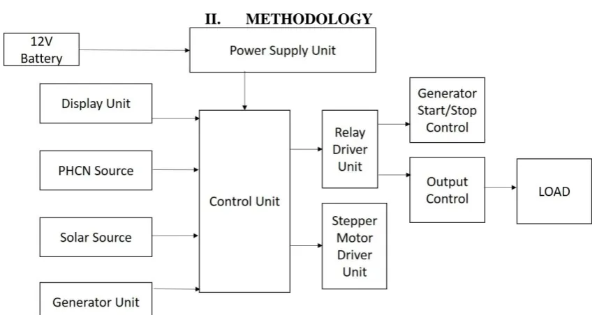
Figure 1: Block diagram showing the working principle of a hybrid power control system
The various units involved are as follows:
I. Power supply unit (12V battery, smoothing capacitor and the voltage regulator). II. Power supplies (Mains Utility, Photovoltaic System, Generator)
III. Visual display unit (LCD) IV. Load control (contactors) V. Microcontroller circuit
The power supply unit consists of 12V battery, smoothing capacitor and voltage regulator. It supplies 12V needed to power the relays. The 12V input also undergoes voltage regulation and is smoothened by smoothing capacitor to give an output of 5V that serves as the supply for the microcontroller and LCD.
The microcontroller unit circuit is the heart of the project. This is where the program for the control part of the project is written and burned using assembly language and a universal programmer, respectively. The control unit also contains drivers for the relay and stepper motor.
The sequence of operation of the circuit is as follows
a. The circuit sequence is such that at turn on, it initialises the LCD.
b. Then, it checks to see if mains supply is available, if not, the circuit checks the battery level of the photovoltaic system and switches the load to it.
c. If after the sequence, the battery of the inverter is low (at 15%), the circuit de-energises the photovoltaic contactor,
d. Then it activates the generator start sequence and energises the generator contactor.
e. If the generator is available, the load is supplied with generator and waits for mains supply to come back on.
f. If the mains supply comes on when the circuit is running on generator, it activates the generator stop sequence,
g. De-energises the generator contactor, energises the mains supply contactor and loads the circuit on mains supply,
h. Then turns off the generator (fan) after a delay sequence
i. On the other hand, if mains supply is available, it turns on the mains supply relay and waits till mains supply fails.
Figure 2: LCD connected to the microcontroller
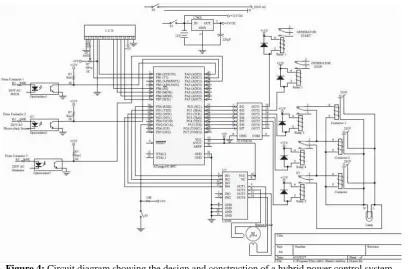
Figure 3: Circuit diagram of the five relays and three contactors used in this design
III.
PERFORMANCE EVALUATION
In order to test the performance of the system, contactor M is the contactor controlling the mains supply, contactor P is the contactor controlling the photovoltaic source, contactor G is the contactor controlling the generator source, switch O is the reset switch. A 60W bulb is used as the load (though the circuit can power a complete building, and that was the reason why contactor was chosen) and a 12 Volts battery is used to supply the Power Supply Unit of the circuit.
The following steps were involved in the operation of the circuit: a. Contactor M de-energized (OFF) simulates mains supply outage. b. Contactor P de-energized (OFF) simulates photovoltaic supply outage. c. Contactor G de-energized (OFF) simulates unavailability of generator source. d. Contactor M energized (ON) simulates mains supply availability.
e. Contactor P energized (ON) simulates photovoltaic supply availability. f. Contactor G energized (ON) simulates generator source availability. g. Switch O opened (OFF) simulates only mains supply at any time. h. Switch O closed (ON) simulates normal HPCS operation. i. Bulb ON means the 60W bulb lights by any of the three source
Figure 5: Completed circuit of the hybrid power control system
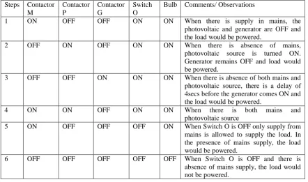
Table 1: Summary of performance evaluation Steps Contactor
M
Contactor P
Contactor G
Switch O
Bulb Comments/ Observations
1 ON OFF OFF ON ON When there is supply in mains, the photovoltaic and generator are OFF and the load would be powered.
2 OFF ON OFF ON ON When there is absence of mains, photovoltaic source is turned ON. Generator remains OFF and load would be powered.
3 OFF OFF ON ON ON When there is absence of both mains and photovoltaic source, there is a delay of 4secs before the generator comes ON and the load would be powered.
4 ON ON OFF ON ON When there is both mains and photovoltaic source
5 ON OFF OFF OFF ON When Switch O is OFF only supply from mains is allowed to supply the load. In the presence of mains supply, the load would be powered.
IV.
CONCLUSION
The device was analyzed and tested. Based on the test results, the whole system performed according to the designed aim and objectives of the project. The hybrid power control system (HPCS) circuit was able to switch between the three power supply sources according to the set priority and also automatically switch on the generator and switch it off.
The device has been proven to be reliable and can be deployed in houses, offices, industrial settings and all environments where constant power supply is of great importance. With improved rating of the solar system and generator, more percentage of loads can be placed on them.
The present system is an improvement to both automatic and manual power change over.
REFERENCES
[1]. Agbetuyi, A. F., Adewale, A. A., Ogunluyi, J. O., & Ogunleye, D. S. (2011). Design and Construction of an Automatic Transfer Switch for a Single Phase Power Generator. International Journal of Scientific and Engineering Research, 2(May), 1–8.
[2]. Ahmed, M. S., Mohammed, A. S., & Agusiobo, O. B. (2006). Development of a Single Phase Automatic Change Over Switch. AU Journal of Technicial Report, 10(1), 68–74.
[3]. Amuzuvi, C. K., & Addo, E. (2015). A Microcontroller Based Automatic Transfer Switching System for a Standby Electric Generator. Ghana Mining Journal, 15(1), 85–92.
[4]. Brown, B., Guditis, J., Critical, S. D., & Competency, P. (2006). Critical-Power Automatic Transfer Systems – Design and Application. IEEE Central TN Section, 1(August), 1–18.
[5]. C, E. K., Uchenna, N., Henry, O. kelechi, & Amaka, E. (2015). Microcontroller Based Power Change-Over Switching System With Generator Shutdown. Journal of Multidisciplinary Engineering Science and Technology, 2(8), 2184–2189.
[6]. Christian, M. (2012). Smart Phase Change-over system with AT89C52 Microcontroller. Journal of Electrical and Electronics Engineering, 1(3), 31–34.
[7]. Chukwuemeka, C., Babajide, O., John, O., Agidani, J., & Onyedikachi, V. (2015). Design and Implementation of Microcontroller Based Programmable Power Changeover. Computer Engineering and Intelligent Systems, 6(12), 51–56.
[8]. Ezema, L. S., Peter, B. U., Harris, O. O., & Power, E. (2012). Design of Automatic Change Over Switch With Generator Control Mechanism. Natural Anf Applied Sciences, 3(3), 125–130.
[9]. Kolo, J. G. (2007). Design and Construction of an Automatic Power Changeover Switch. AU Journal of Technicial Report, 11(2), 1–6.
[10]. Okome, O., & Oladipo, F. (2015). AUTOMATIC TRANSFER SWITCH WITH THREE PHASE SELECTOR.docx. International Journal of Scientific and Engineering Research, 6(7), 81–87.