A Prototype for Double Output Load System of
Bridgeless AC-DC Rectifier in Single Switch
Control
J. Stanly jones1, Dr.S.Sutha2 1, 2
Department of Electrical and Electronics Engineering, University College of Engineering, Dindigul, Tamilnadu, India
Abstract: In power factor correction field is most important for the electrical and electronics applications, particularly the active PFC topology is involving this PFC correction applications, in beginning the diode bridge rectifier acts that process, but power factor cannot achieved .So, the researchers following active PFC correction topology of DC-DC converter commonly need in this process namely CUK converter, the bridgeless topology in the DCM method and double output load systems operating in the single switch control for low power output systems, this load systems are operating in low power, one is LED another one a simple DC motor, however in this paper the power factor achieved nearly unity. The hardware implementation will achieve for low power applications.
Keywords: Power Factor Correction (PFC), Light Emitting Diode (LED), Discontinuous Conduction Mode (DCM),
I. INTRODUCTION
The most of the industries or electronic applications, the power factor is very important for equipments. In lighting field, the LED is very popular for load system which used by the power electronic field’s researchers. Commonly the LED is head resist; many type of the LED will be introduced by the industries [1]. Another one is DC motor is used in the most of the application, this paper type of motor can introduced for low power applications. Many power supply manufacturing companies focused to bridgeless topology for Power factor correction, and bridgeless boost to reduce the common mode noise [2]. The diode bridge rectifier is a non linear load and bulky capacitor is discontinuous charging, for this reasons the researchers used bridgeless schemes [3]. Output capacitor ripple current is high and also degrade the efficiency in this topology [4]. The power factor correction is basic fundamental for SMPS, it can be reduced the voltage and current distortion and also reducing the losses, it has several converters such as buck, CUK, SEPIC, buck boostetc [5].
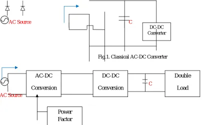
[image:2.612.41.445.469.719.2]AC Source C
Fig.1. Classical AC-DC Converter
C
AC Source
The classical boost bridgeless scheme is generally utilized converter for its usage, it have simple circuit, and have simple control structure[8],[9], high efficiency also achieved, EMI and conduction losses are reduced [6],[7], but input voltage can stepped up process only, so this type of converter may not be using for low power application[10].For this reason the bridgeless CUK PFC topology is introduced in this paper, in this topology conduction losses and noise emission are reduced [11]. Maximum number of the semiconductor devices requirements are avoided in [12], [13]. The important problems of power factor correction issues are find out in [14]. The startup inrush current problems are solved by this CUK converter topology thatit strongly protection against high inrush current [15],[16].
II. A PROTOTYPE BRIDGELESS CUK PFC RECTIFIER SYSTEM:
The bridgeless CUK rectifier will be achieved in the hardware, In this prototype usually achieved Power factor, efficiency, that can be performed load side because in this paper particularly focused low power applications, in which high input voltage step down by DC-DC converter that can performed step up/step down, these converter is namely CUK. This type of converter commonly used in the power factor correction field, that easily flexible. Sothis prototype two loads operated by low power. If high loads are in system, defiantly the power factor will affect or some of heat will produce the equipments, for this reason low power loads are involved this prototype. The circuit diagram of the hardware is given in the below. In this circuit diagram one switch handled two loads, one is simple DC motor another one is the LED, this is very simple, low cost and operating ways are very easy to handlers. That will be application for home and minimum power usage areas, because now a day maximum electrical and electronics home power applications work done and needs low power, for this rason we are try simple model of this hardware implementation.
L1
Vac 230 V
Dp Dn
C1 + C2 + Q1 Q2 Lo1 Do1 Do2 Lo2 Co Iac IL1 IL2
Stepped down rectifier.
Sw itch ON for LED
20 Watts LED Light L2
L1
Vac 230 V
Dp Dn
C1 + C2 +
Q1 Q2 Lo1 Do1 Do2 Lo2 Co Iac IL1 IL2
Stepped down rectifier.
Switch ON for
L2
DC Motor
25-35 Watts DC motor
Fig.3. Proposed bridgeless CUK for LED & DC load
Fig.4. Hardware diagram for CUK configuration.
In the hardware system, microcontroller acts as a isolation between the converter circuit and control systems, MOSFETs are used to trigger the PWM signals. The microcontroller controls the internal diodes. The atmega 328 processor is used for the PWM generation and LED and DC motor is connecting for the output loads. And power factor is achieve almost 0.9 – 0.95 and also improve the efficiency. The hardware system is given in th below.
III. RESULT AND DISCUSION
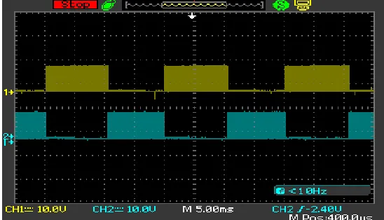
[image:4.612.79.424.345.513.2]Voltage and current waveform shown in the figure 6
Fig. 5. Voltage and current wave forms of the proposed converter
Represents the input voltage and current wave forms of the proposed converter with a voltage and current in phase during the power conversion
[image:4.612.169.443.558.715.2]Switching signals of the MOSFETS S1,S2 which are alternate in phase used to convert the ac power to dc. During the positive half cycle of the input voltage the gating signal is applied to switch Q1.
Fig.7. Represents the reference and the trigger PWM generation
Represents the reference and the trigger PWM generation is shown in the figure 16. During the negative half cycle of the input voltage the gating signal is applied to switch Q2.
IV. CONCLUSION
Finally the AC-DC rectifier hardware gives almost good power factor and high efficiency and double output load system successfully controlled by the single switch, in which process for low power application that used in the home application. So from this experiment we know that, in future researchers implement and design the maximum of new topologies are may be introduce.
REFERENCES
[1] A Guide to the Specification of LED Lighting Products” 2012 the umbrella of the Lighting Industry liaison group.
[2] Laszlo Huber, Yungtaek Jang, Milan M. Jovanovic,” Performance Evaluation of Bridgeless PFC Boost Rectifiers”, IEEE transactions on power electronics, vol. 23, no. 3, may 2008.
[3] Sanjeev Singh*, Bhim Singh,” Power Factor Correction In Permanent Magnet Brushless Dc Motor Drive Using Single-Phase Cuk Converter”, Journal of Engineering Science and Technology Vol. 5, No. 4 (2010) 412 – 425.
[4] FariborzMusavi, Wilson Eberle and Wiliam G. Dunford, “Efficiency Evaluation of Single-Phase Solutions for AC-DC PFC Boost Converters for Plug-in-HybridElectric Vehicle Battery Chargers”,
[5] Nesapriya. P., S. Rajalaxmi,” Closed Loop Control of Bridgeless Cuk Converter Using Fuzzy Logic Controller for PFC Applications,” International Journal of Electrical, Computer, Energetic, Electronic and Communication Engineering Vol:7, No:11, 2013.
[6] FariborzMusavi,Murray Edington, Wilson Eberle, William G. Dunford,” Evaluation and Efficiency Comparison of Front End AC-DC Plug-in Hybrid Charger Topologies”. IEEE transactions on smart grid, vol. 3, no. 1, march 2012.
[7] Xiang LU,Yunxiang XIE, Li CHENG, Zhiping WANG and Cunbing GUI, “Semi-Bridgeless Boost PFC Rectifier for Wide Voltage Input Range Based on Voltage Feed-Forward Control”, 2012 IEEE 7th International Power Electronics and Motion Control Conference.
[8] Yun-Sung Kim, Won-Yong Sung, Byoung-Kuk Lee, “Comparative Performance Analysis of High Density and Efficiency PFC Topologies”, IEEE transactions on power electronics, vol. 29, no. 6, june 2014.
[9] Sachin K. Kupati, MukulChavan, Sunil Bhattad and N. Arun, “Average Current Mode Controlled Power Factor Correction Converter”,Indian Journal [10] Xiang Lin, Faqiang Wang, “A Novel Bridgeless Buck PFC Converter With Half Dead Zones”, 978-1-4673-8644-9/16/ 2016 IEEE.
[11] AyshaKemaidesh AL-Kaabi, Abbas A. Fardoun1 and Esam H. Ismail, “High efficiency Bridgeless Unity Power factor CUK converter Topology”,International Conference on Renewable Energies and Power Quality (ICREPQ’13) March 2013.
[12] Siriki.s.m.ravikumar, T. SrinivasaRao, K.durgarao, “New Efficient Bridgeless Cuk Rectifiers for PFC Application on d.c machine”, Volume 9, Issue 1 (November 2013), PP. 15-21.
[13] Jibin George, RabiyaRasheed, “ Modelling of Cuk Rectifier for Power Factor Correction,” International Journal of Engineering and Innovative Technology (IJEIT) Volume 3, Issue 2, August 2013.
[14] R. Balamurugan, R. Nithya, and R. Senthilkumar, “Power Factor Improvement Using Single Phase Bridgeless Cuk Converter Topology Based on Fuzzy Logic Control”, International Journal of Fuzzy Systems, Vol. 15, No. 4, December 2013.
[15] FariborzMusavi, Wilson Eberle, William G. Dunford, “A Phase-Shifted Gating Technique With Simplified Current Sensing for the Semi-Bridgeless AC–DC Converter”, IEEE transactions on vehicular technology, vol. 62, no. 4, may 2013.