Technology (IJRASET)
©IJRASET 2015: All Rights are Reserved
405
Matlab Simulation on Photovoltaic Boost Half
Bridge Multilevel Inverter System Using Mppt
Abstract: In order to achieve low cost, easy control, high efficiency, and high reliability this project presents a novel Photovoltaic boost half-bridge multilevel inverter system using repetitive current control and maximum power point tracking (MPPT) with its control implementations. A boost half-bridge dc-dc converter using minimal devices is introduced to interface the low voltage PV module. A multilevel pulse width modulated inverter is cascaded and injects synchronized sinusoidal current to the grid. More over a plug in repetitive current control is proposed to control the grid current. A customized maximum power point tracking (MPPT) method which generates a ramp-changed PV voltage reference. High power factor and very low total harmonic distortions are guaranteed under both heavy load and light load conditions. Maximum power point tracking (MPPT) and repetitive current controller is used to improve the performance and efficiency. The Simulation is done and Photovoltaic boost half-bridge multilevel inverter results are connected to grid.
Keywords: boost half bridge, maximum power point tracking (MPPT), photovoltaic multilevel inverter, repetitive current control, grid connected photovoltaic (pv) system.
I. INTRODUCTION
PhotoVoltaic (PV) generation is becoming increasing important as a renewable source since it offers many advantages such as low fuel cost, pollution free,less maintenance, and not getting noise and it doesn't realse harmfull gases,observe to others. Among a variety of the renewable energy sources, photovoltaic (PV) sources have no control power supply and are predicted to become the biggest contributors to electricity generation among all renewable energy candidates by 2040. PV modules have relatively low conversion efficiency.To regulating Maximum Power Point Tracking (MPPT) for the solar array is essential in a PV system. The electric power given by a photovoltaic power generation system calculate on the solar radiation.designing efficient PV systems heavily charge to track the maximum power operating point. The amount of power generated by a PV calculate on the operating voltage of the array. A PV’s Maximum Power Point (MPP) varies with solar insulation and temperature. It’s V-I and V-P characteristic curves specify a unique operating point at which maximum possible power is sent. At the MPP, the PV operates at its highest efficiency.
Multilevel Inverter System (MIS) has become a future trend for single phase grid connected photovoltaic system. MIS is the combination of boost half bridge converter and full bridge inverter. A PV array is formed by series/parallel combination of solar modules. Hence, a boost-half-bridge DC-DC converter cascaded by an inverter is the most popular topology, in which a High Frequency (HF) transformer is often implemented within the DC-DC conversion stage. By replacing the secondary half bridge with a diode voltage doubler, a new boost-half-bridge converter can be derived for unidirectional power conversions . The promising features such as low cost, high reliability and high efficiency, circuit simplicity can be obtained by use of the converter with minimal semiconductor devices. The repetitive current control technique is an effective solution for the elimination of periodic harmonic errors and has been previously investigated and validated in the un-interruptible power system, active power filters, boost-based Power Factor Correction (PFC) circuits, and grid-connected inverters /PWM rectifiers
The synchronized sinusoidal current can be injected to the grid by using a full bridge PWM inverter with an output LCL filter. Sinusoidal current with a unity power factor is supplied to the grid through a third-order LCL filter. In general, its performance is evaluated by the output current Total Harmonic Distortions (THDs), power factor, and dynamic response. The maximum Power Point (MPP) is the point in which maximum power is delivered from the solar cell to the PV system. MPPT is performed by the boost-half-bridge converter by using numerous MPPT techniques such as Perturb and Observe Method, Incremental Conductance Method, Ripples Correlation Method, etc. A closed-loop control technique has been proposed to minimize the PV voltage oscillation.
In this paper, the concept of multilevel Inverter (MLI) is kind of modification of two-level inverter. In multilevel inverters we don’t deal with the two level voltage instead in order to create a smoother stepped output waveform, more than two voltage levels are combined together and the output waveform obtained in this case has lower dv/dt and also lower harmonic distortions. Smoothness of the waveform is proportional to the voltage levels, as we increase the voltage level the waveform becomes smoother but the complexity of controller circuit and components also increases along with the increased levels. The waveform for the three, five and seven level inverters is shown in the Figure where we clearly see that as the levels are increasing, waveform becoming smoother.
©IJRASET 2015: All Rights are Reserved
406
Fig. In past the system was based on centralized inverters that interfaced a large numbers of modules to the grid. The PV modules were divided into series connections (called a string), each generating a sufficiently high voltage to avoid further amplification. Losses in the string diodes and a non flexible design where the benefits of mass production could not be reached. The present technology consists of the string inverters and the module. Where a single string of PV modules is connected to the inverter. Several strings are interfaced with their own dc-dc converter to a common dc-ac inverter. Since every string can be controlled individually.
B. Boost-Half Bridge: According To F.Z.Peng, H.Li, G.Su And J.S Lawer
A boost dual-half-bridge dc–dc converter for bidirectional power conversion applications was first proposed in and then further investigated. The boost converter and the dual half bridge converter together are integrated by employing minimum number of devices. The Zero voltage switching (ZVS) technique produces high efficiency. Alter the secondary half bridge with a diode voltage doubler, so that a new boost half bridge converter can be obtained for unidirectional power applications. In this paper, the boost half- bridge converter is incorporated as the dc–dc conversion stage for the grid-connected PV micro inverter system. This circuit is very simple, easy control and it requires minimal semiconductor devices. The features of this are low cost, high efficiency and high reliability.
C. Multilevel Inverter
According to Hosseini Aghdam, M.G.; Fathi, S.H.; Gharehpetian, G.B, Zhong Du; Tolbert, L.M.; Chiasson, J.N.; Ozpineci, B.;, G. Sinha and T. A. Lipo, M. Klabunde, Y. Zhao, and T. A. Lipo. Cascade Multilevel Inverter (CMLI) is one of the most important topologies in the family of multilevel and multipulse inverters. It is built to synthesize a desired AC voltage from several levels of DC voltages. The DC levels are considered to be identical since all of them are either batteries, solar cells, etc. It requires least number of components when compared to diode-clamped and flying capacitors type multilevel inverters and no specially designed transformer is needed as compared to multi pulse inverter.
D. Plug-In Repetitive Current Controller
According to G. Shen, D. Xu, L. Cao, and X. Zhu, J. Dannehl, M. Liserre, and F. W. Fuchs, For reducing the current harmonics the around the switching frequency, improving the system dynamic response, reducing the total size and cost, an LCL filter with a grid connected inverter system is an attractive solution. Typically, an undamped LCL filter exhibits a sharp LC resonance peak, which indicates a potential stability issue for the current regulator design. To attenuate the resonance peak below 0 dB, either passive damping or active damping techniques can be used. On the other hand, a current regulator without introducing any damping method can also be stabilized, as long as the LCL parameters and the current sensor location are properly selected. In this paper, the LCL parameters are selected by following the guidelines provided. In the inverter side, the current sensor is placed. Therefore no damping techniques are needed.
III. MODULES A. Multilevel Inverter
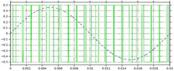
Mostly a micro inverter is used in order to generate the AC voltage from DC voltage. A two-level Inverter creates two different voltages for the load i.e. suppose we are providing Vdc as an input to a two level inverter then it will provide + Vdc/2 and –
[image:3.595.146.447.663.786.2]Vdc/2 on output. In order to build an AC voltage, these two newly generated voltages are usually switched. For switching mostly PWM is used as shown in the Figure , reference wave is shown in dashed blue line. Although this method of creating AC is effective but it has few drawbacks as it creates harmonic distortions in the output voltage and also has a high dv/dt as compared to that of a multilevel inverter. Normally this method works but in few applications it creates problems particularly those where low Total Harmonic distortion in the output voltage is required .To reduce the THD values the output is effectively generated. By reducing the THD values and less switching losses a multilevel inverter is proposed.
Technology (IJRASET)
©IJRASET 2015: All Rights are Reserved
407
Fig: Architecture of PV micro inverter system
A Multilevel inverter is a power electronic device which is capable of providing desired alternating voltage level at the output using multiple lower level DC voltages as an input. Inverters are commonly used in consumer and industrial applications. The output voltage of an inverter can be controlled indifferent ways. The most common method consists of controlling the pulse width modulation applied to MOSFETs IGBTs etc. In general with two level inverter more harmonics are produced which increases losses and cause heat problems in the machine, resulting in wear of the insulation covering the conductors and reducing the motor performance. To reduce these harmonics multilevel inverter is designed. Multilevel inverters include an arrangement of semiconductors and dc voltage sources required to generate a stepped output voltage waveform. The number of input DC voltages depends on the number of inverter output voltage levels and as the levels are increased the harmonics are reduced.
Multilevel power converter structure has been introduced as an alternative in high power and medium voltage situations; it decreases the harmonic distortion in the output waveform. A multilevel converter not only achieves high power ratings, but also improves the performance of the whole system in terms of harmonics; multilevel inverters are a source of high power, often used in industrial applications and can use either sine or modified sine waves. Instead of using one converter to convert an AC current into a DC current, a multilevel inverter uses a series of semi conductor power converters which are (usually 2-3) thus generating higher voltage. While with an inverter you would transfer energy with the flip of one switch, with a multilevel inverter you would have to flip several switches, each switch requiring a circuit. A relatively new class called multilevel inverters has gained widespread interest. Normal operation of CSIs and VSIs can be classified as two-level inverters because the power switches connect to either the positive or the negative DC bus If more than two voltage levels were available to the inverter output terminals, the AC output could better approximate a sine wave. For this reason multilevel inverters, although more complex and costly, offer higher performance.
1) The Advantages of Cascade H Bridge Multilevel Inverters
Output voltages levels are doubled the number of sources Manufacturing can be done easily and quickly
Packaging and Layout is modularized. Easily controllable with a transformer. Cheap.
B. Cascaded Multilevel Inverter
©IJRASET 2015: All Rights are Reserved
408
Fig : Single phase cascaded multilevel inverter
[image:5.595.187.418.286.410.2]The ac output of each H-bridge is connected in series such that the synthesized output voltage waveform is the sum of all of the individual H-bridge’s outputs. By connecting the sufficient number of H-bridges in cascade and using proper modulation scheme, a nearly sinusoidal output voltage waveform can be synthesized. The Figure shows the connecting diagram of single phase cascaded inverter.
Fig : Waveform of m-level multi inverter
In this concept proposed cascaded multilevel inverter is connected instead of full bridge inverter control in the block diagram output will change.
C. PV Boost Half Bridge Multi Level Inverter Simulation Diagram
In the proposed Boost –Half-Bridge PV multi inverter system diagram of PV system and MPPT and Boost-Half-Bridge converter and full- Bridge Inverter are designed in Mat lab/Simulink. The control circuit diagrams for Boost-Half-Bridge converter and full-Bridge inverter designed in Mat lab/Simulink are shown in below figures. The simulation circuit diagram for PV system design is shown in below figure the entire PV system design and MPPT algorithm is designed in Matlab\Simulink. The simulation circuit diagrams for Boost-Half-Bridge converter control and consists of MPPT block and duty cycle generation and PWM generator and s1 ands2 denote duty cycles of Half-Bridge converter. Here IPV and VPV are first sensed and those are
[image:5.595.133.449.625.779.2]given to the MPPT function block MPPT function block generates Maximum power point based on that duty cycles of Half – bridge converter S1 and S2 are adjusted. The simulation circuit diagrams for Full-Bridge –Inverter control is shown in below
figure. Here the grid voltage Vg is sensed we are getting the angle which is known as phase lock loop the Vdc1 and Vdref are
compared and which are given to the discrete PI control the PV cell power Ppv and Vg are divided to get the current which is
operated to the load.
Technology (IJRASET)
©IJRASET 2015: All Rights are Reserved
409
[image:6.595.111.470.96.175.2] [image:6.595.188.398.289.451.2]The following figure shows the sub system of the repetitive current control for the full bridge inverter control.
Fig :Simulation Circuit Diagram for Repetitive Control Block
IV. RESULTS
A. System Output Waveforms
[image:6.595.51.320.515.771.2] [image:6.595.168.527.516.772.2]1) PV Boost Half-Bridge Multi Level Inverter Under Light Load.: The proposed simulation circuit diagram designed in Matlab/Simulink under heavy load conduction is shown in below figure4.1. In this circuit the load is connected to the proposed circuit
Fig :Simulation Circuit Diagram Under Light load
The PV cell output current and output voltage and output power wave forms and waveform for the sinusoidal current injected to the grid for the PV boost half bridge multi level inverter are shown in below figures.
Fig : PV cell output voltage Fig :PV cell output power
©IJRASET 2015: All Rights are Reserved
410
The proposed simulation circuit diagram designed in Matlab/Simulink under heavy load conduction is shown in below figure 6.10. In this circuit the load is connected to the proposed circuit
Fig : Simulation circuit under heavy load
[image:7.595.178.409.123.289.2]The waveform of output voltage and current for the grid for the PV boost half bridge multi level inverter under heavy load are shown in below figure .
Fig :Output voltage and current under heavy load condition
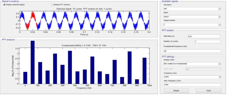
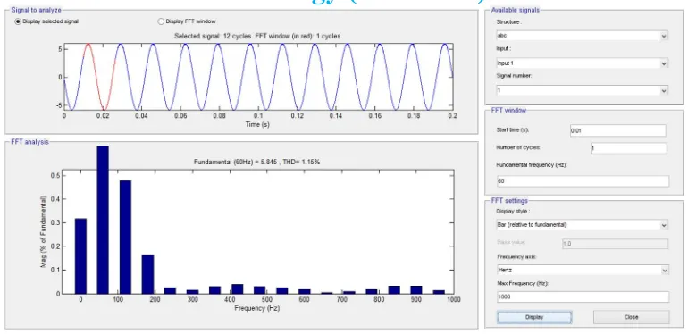
3) FFT Analysis for Total Harmonic Distortion
[image:7.595.108.491.591.753.2]The output current total harmonic distortions (THDs) by conducting the FFT analysis for the output wave forms as shown in the following figure so that the performance can be determined.
Technology (IJRASET)
[image:8.595.106.491.74.261.2]©IJRASET 2015: All Rights are Reserved
411
Fig :Analysis of THD with a multi level inverter
V. CONCLUSION
A PV boost half-bridge multi level inverter connected to the grid has been presented. The minimal use of semiconductor devices, circuit simplicity, and easy control, the boost-half-bridge PV multi level inverter possesses features of low cost and high reliability. The PV boost- half-bridge dc–dc converter has a high efficiency (96.0%– 98.0%) over a wide operation range. And also the current injected to the grid was regulated precisely and stiffly. According to the experimental results under both heavy load and light load conditions, high power factor (>0.981) and low THD (0.9%–2.8%) were obtained.
The ramp-changed reference generated by the customized MPPT method for the PV voltage regulation guarantees a correct and reliable operation of the PV micro inverter system was. Fast MPP tracking speed and a high MPPT efficiency (>98.7) is achieved by the variable step-size technique provides a correct and reliable operation of the PV micro inverter system. As a result the proposed PV boost half-bridge multilevel inverter system with its advanced control implementations will be competitive for grid-connected PV applications.
VI. FUTURE SCOPE
Our future concept, cascaded H-bridge multilevel inverter is used .To increase the number of levels the low Total Harmonic Distortion will occur that tends to reduce losses and increase the efficiency.
REFERENCES
[1] Soeren Baekhoej kjaer,John K.Pedersen and Frede Blaabjerg, “A Review of Single-Phase Grid connected Inverters for photovoltaic modules”.Ieee Transactions On Industry Applications,Vol.41,No.5,pp.1292-1306 September/October 2005.
[2] F. Z. Peng, H. Li, G. Su, and J. S. Lawler, “A new ZVS bidirectional DC– DC converter for fuel cell and battery application,” IEEE Trans. Power Electron., vol. 19, no. 1, pp. 54–65, Jan. 2004.
[3] Hosseini Aghdam, M.G.; Fathi, S.H.; Gharehpetian, G.B,“Comparison of OMTHD and OHSW harmonic optimization techniques in multi-level voltage-source inverter with non-equal DC voltage-sources,” in Proc. 7th IEEE Power Electron. Spec. Conf. (ICPE), 2007, pp. 587 – 591.
[4] Zhong Du; Tolbert, L.M.; Chiasson, J.N.; Ozpineci, B.;, “A cascade multilevel inverter using a single DC source,” ,” in Proc. IEEE APEC’06, 2006, pp. 426 – 430.
[5] G. Sinha and T. A. Lipo, “A four level rectifier-inverter system for drive applications,” in Conf. Rec. 31st IEEE IAS Annu. Meeting, 1996, vol. 2, pp. 980–987.
[6] M. Klabunde, Y. Zhao, and T. A. Lipo, “Current control of a 3 level rectifier/inverter drive system,” in Conf. Rec. IEEE IAS Annu. Meeting, 1994, vol. 2, pp. 859–866.
[7] G. Shen, D. Xu, L. Cao, and X. Zhu, “An improved control strategy for grid-connected voltage source inverters with an LCL filter,” IEEE Trans. Power Electron., vol. 23, no. 4, pp. 1899–1906, Jul. 2008.