Analysis of Transformer Bushing Failure Based on
Frequency Response Analysis (FRA)
A.Srikanth1, Dr. K. Shashidhar Reddy2, Sangeetha C.N3, Dr. M. Surya Kalavathi4
1,3
Asst.Professor, EEE Dept, St. Martin’s Engineering College
2
Professor, EEE Dept, St.Martin’s Engineering College
4
Professor, EEE Dept, JNTUH, Kukatpally, Telangana
Abstract: Frequency Response Analysis (FRA) is the most reliable technique for detecting any failure within electrical power transformers. In this paper the FRA technique to identify non-mechanical faults such as transformer bushing failures. The transformer failure on the mark of the FRA strategy has been explored, no standard code has been broadly received. Moreover, the FRA technique is ineligible in identifying minor levels of energy transformer fault that declines the transformer's capacity to withstand any further electrical, thermal and mechanical stresses. The FRA technique properly, the base discovery of transformer issues ought to be evaluated. This paper expects to recognize the effect of the base level of transformer bushing failure on the FRA signature that can be outwardly identified. A 3-phase control transformer is recreated (in light of the Finite Element Analysis (FEA) technique) to mirror its genuine operation amid both solid and broken conditions. The effect FRA marks (in light of FEA) for different bushing failure levels was acquired and afterward contrasted with the solid mark, and varieties are distinguished in the event that they exist. Results demonstrate that the transformer bushing failure has a base level that can be outwardly recognized utilizing the FRA technique.
Keywords: Power transformer, Transformer bushing failure, Frequency response analysis.
I. INTRODUCTION
The substantial power transformers have a place with the most costly and deliberately imperative segments of any generation and transmission system. A genuine failure of a large power transformer because of insulation breakdown can produce generous expenses for repair and money related misfortunes because of influence blackout. Subsequently, utilities have clear motivator to evaluate the genuine state of their transformer, specifically the state of the HV insulation framework, with the plan to limit the danger of disappointments and to stay away from constrained blackouts of deliberately imperative units. Appraisal of insulation quality in expansive H.V. control hardware anytime, additionally called 'Condition Monitoring' is a territory of work presently being sought after by numerous research facilities and utilities. A few systems are accessible for observing of a few parameters, which could show the condition on the insulation. From the writings and in addition field information it has been set up that bushings are one of the real purposes behind transformer disappointment. With this foundation, it has been the subject of this examination work to build up an on-line molding observing system to screen the status of a bushing.
II. TRANSFORMERBUSHINGDESIGN
development bowl . A best terminal is given to interface with the over head line. Arcing horns are given on ask for in the middle of best shield and base plate.
Fig.1. The general constructional diagram of bushing
III. BUSHINGCIRCUITMODELING
Fig.2. Equivalent Circuit model of bushing
mixes of both arrangement and parallel resistors (eight combinational circuits were dissected). This has been done to build up the affectability of the method to equal circuit portrayal and comprehend the physical wonders.
IV. FREQUENCYRESPONSEANALYSIS
The frequency response of the built bushing model is contemplated by systematic technique. Analytical technique is utilized as this fits consider the varieties in parameters rapidly for a given proportionate circuit portrayal. In investigative technique scientific models are created in light of the identical circuit parameters and these are utilized to determine the yield capacities for any given info flag. The yield flag is determined over the last area of the identical circuit and the info is connected over the whole series of arrangement areas. The yield is examined for different conditions like no fault, 3 % and 10% change in insulation and capacitance. The explanatory models are of the form
VI = I (Z1+ Z2 +…..+Z10+ Zo ) and Vo= IZo Transfer function =Vo (s) / Vi(s) = Zo / (Z1 + Z2 +Z3 +….Z10 + Zo )
The FRA technique is directed on the 40MVA transformer to get a solid FRA magnitude signature by infusing a variable frequency low amplitude AC voltage (vin) at one terminal of the HV winding, and measuring the reaction signal over another terminal of HV winding (vout). The FRA mark of the 40MVA transformer HV winding is plotted as a transfer function work for the three phases (A, B and C) shown in Figure
Fig.3. HV and LV windings FRA analysis.
As can be found in Fig.3, the marks are characterized by resonances and anti-resonances frequencies over the whole frequency. As the frequency expands, more space harmonics are developed in the winding. At a low frequency range, resonances and anti-resonances frequencies are influenced by the inductive segments while the impact of capacitive segments is appeared in the high frequency run. Further, the FRA marks of the three phases are practically indistinguishable aside from the center (phase B). This variety can be ascribed to the slight contrast of the attractive motion amid phase B (contrasted with phases A and C).
V. FRAIMPACTOFTRANSFORMERBUSHINGFAILURE
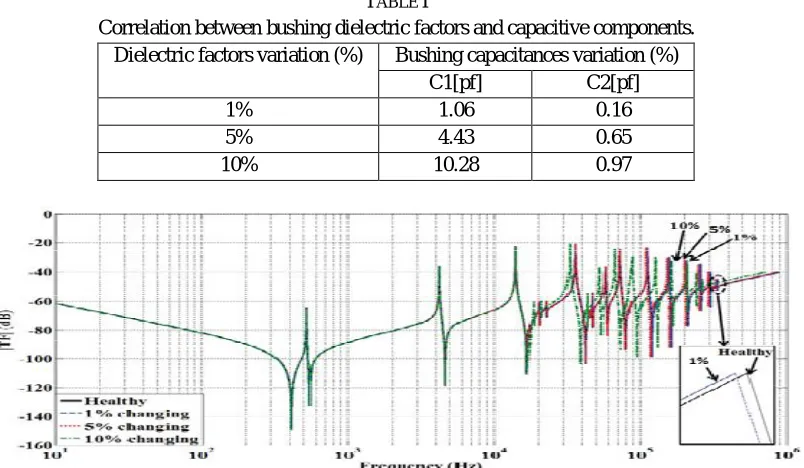
TABLE I
Correlation between bushing dielectric factors and capacitive components. Dielectric factors variation (%) Bushing capacitances variation (%)
C1[pf] C2[pf]
1% 1.06 0.16
5% 4.43 0.65
10% 10.28 0.97
Fig.5. The failure levels of transformer bushing of 40MVA transformer HV winding on FRA signature.
As appeared in Figure 5, the effect of a 1% transformer bushing failure (changing the dielectric elements of transformer bushing by 1%) on the 40MVA transformer HV winding stage A FRA mark is gotten and contrasted with a sound mark. As uncovered Figure5, the sound and broken marks are practically indistinguishable, and it is hard to recognize any variety. A slight variety however can be outwardly recognized in the high recurrence go (50 kHz) when the transformer bushing failure increments to 5% (as appeared in Figure 5) that movements resonances and hostile to resonances frequencies in the high recurrence range to one side. The effect of the transformer bushing failure on the FRA signature turns out to be more articulated when the bushing failure level is expanded by 10% as appeared in Figure 5.
VI. CONCLUSIONS
This paper discussed about in detail the effect of transformer bushing disappointment on the FRA mark to demonstrate the affectability of bushing disappointment on the FRA strategy and recognize the least disappointment levels that can be recognized outwardly. Results uncover that the FRA mark is influenced by bushing disappointment; however a disappointment level under 5% is hard to identify outwardly utilizing the ordinary understanding procedure of the FRA procedure. Disappointment levels higher than 5% has a visual affect on the FRA signature at a high recurrence extend. Studies ought to be proceeded so as to build up a progressed system of recognizable proof and evaluation of such a minor level.
REFERENCES
[1] O. Aljohani and A. Abu-Siada, "Application of FRA polar plot technique to diagnose internal faults in power transformers," in PES General Meeting | Conference & Exposition, 2014 IEEE, 2014, pp. 1-5.
[2] A. Abu-Siada, N. Hashemnia, S. Islam, and M. A. S. Masoum, "Understanding power transformer frequency response analysis signatures," Electrical Insulation Magazine, IEEE, vol. 29, pp. 48-56, 2013.
[3] A. Abu-Siada and S. Islam, "A Novel Online Technique to Detect Power Transformer Winding Faults," Power Delivery, IEEE Transactions on, vol. 27, pp. 849-857, 2012.
[4] L. M. Geldenhuis, "Power transformer life management," in Electricity Distribution, 2005. CIRED 2005. 18th International Conference and Exhibition on, 2005, pp. 1-4.
[5] M. Arshad and S. M. Islam, "Power transformer condition monitoring and assessment for strategic benefits," Curtin University of Technology Department of Electrical & Computer Engineering, Perth, 2003.
[6] A. Abu-Siada and S. Islam, "A new approach to identify power transformer criticality and asset management decision based on dissolved gas-in-oil analysis," Dielectrics and Electrical Insulation, IEEE Transactions on, vol. 19, pp. 1007-1012, 2012.
[image:5.612.108.510.85.319.2]