Technology (IJRASET)
Constant Power Generation from Wind
Turbine by Wind Tracking
B. Shanmukha Rao1, D. Rajesh2, M. Chandra Mouli3
Electrical & Electronics Engineering Department, Pragati Engineering College, JNT University, Kakinada
Abstract— Now-a-days the Generation of Electrical Energy is increasing by using of Renewable energy resources. Among those wind power generation is mostly preferred because it does not emit any hazardous gases and doesn’t need any fuel cost. The main idea of this paper is to design the wind turbine that changes its direction according to wind speed and wind direction and produces constant output power.IR sensors are used to sense wind direction. A microcontroller with dc motor is used to rotate wind turbine according to wind direction
Keywords— Wind vane, IR sensors, Microcontroller, Motors
I. INTRODUCTION
Renewable Energy Sources are those energy sources which are not polluted to atmosphere. Generally Humans uses of renewable energy such as sunlight, wind, waves, water flow, and biological processes such as anaerobic digestion, biological hydrogen production and geothermal heat. Amongst the above mentioned sources of energy there has been a lot of development in the technology for harnessing energy from the wind [1]. Wind energy is not a constant source of energy. It is pulsating in nature and it varies continuously and gives energy in sudden bursts. That means it varies zero to some storm value. About 50% of the entire energy is given out in just 15% of the operating time. Wind strengths vary and thus cannot guarantee continuous power. It is best used in the context of a system that has significant reserve capacity such as hydro, or reserve load, such as a desalination plant, to mitigate the economic effects of resource variability
Wind is the motion of air masses produced by the irregular heating of the earth’s surface by sun. These differences consequently create forces that push air masses around for balancing the global temperature or, on a much smaller scale, the temperature between land and sea or between mountains. Wind energy is not a constant source of energy. It is pulsating in nature and it varies continuously and gives energy in sudden bursts [2]. That means it varies zero to some storm value. About 50% of the entire energy is given out in just 15% of the operating time. Wind strengths vary and thus cannot guarantee continuous power. It is best used in the context of a system that has significant reserve capacity such as hydro, or reserve load, such as a desalination plant, to mitigate the economic effects of resource variability
II. CONVENTIONAL POWER GENERATION
The control methods of conventional methods are pitch control and yaw control. In pitch control the blades can be turned out or into the world .This results in variation of the force exerted by the wind on the rotor shaft. The advantages of pitch control Good power control, assisted startup, Emergency stop. At high wind speeds, pitch control can be used to keep the power output close to the rated power of the generator. The drawback in this case is extra system complexity in the pitch mechanism and the higher power fluctuations at high wind speeds. Due to presence of gusts, the instantaneous power fluctuates around the rated Mean value of the power. In large wind turbines yaw control is done by stepper motors and in small rating wind turbines yaw control is done by tail vane. The yaw control mechanism can also be used for speed control. The work of yaw control is to continuously orient the turbines along the direction of wind flow in order to capture as much wind as possible. In small turbines, a tail-vane is able to serve this purpose. In large machines, motorized control system is used either by a fan-tail (a small turbine mounted perpendicular to the main turbine) or, in case of wind farms, by a centralized instrument for the detection of the wind direction. Downwind turbines have an inherent property to face the wind as the thrust force automatically pushes the turbine in the direction of the wind. The rotor is made to face away from the wind direction at high wind speeds, thereby reducing the mechanical power. However, this method is seldom used where pitch control is available, because of the stresses it produces on the rotor blades Yawing often produces loud noise, and it is desirable to restrict the yawing rate in large machines to reduce the noise.[3-4]
Technology (IJRASET)
Embedded systems and the microcontroller, IR sensors with the help of microcontroller is employed in this paper which shifts the rotor blades according to wind direction and producing constant power whenever the generator attains its rated speed. Hence by using IR sensors wind tracking can be done effectively and efficiency of wind turbine can be improved.
III. PROPOSED METHOD
The proposed control method to generate the constant power to the loads according to wind direction. Hence prior to the development of embedded systems and the microcontroller, IR sensors with the help of microcontroller are employed in this paper which shifts the rotor blades according to wind direction. Schematic diagram of proposed control method as shown in figure 1.
Fig. 1
A. Wind Vane
A wind vane, also known as a weather vane, is a tool used to determine the direction the wind is blowing from. It is a light weight instrument
1) Construction: When constructing a weather vane, the design must be planned to allow for free movement about the vertical axis. The surface area of the design must be asymmetrical, unequal, which enables the smaller area to turn into the wind. However, the weight must be equally distributed on both sides of the axis of rotation to allow the wind vane to spin freely. The small end points in the direction from which the wind is coming and the larger end points where the wind is going. The individual installing the wind vane would need to align the directional markers with the geographic directions of north, south, east and west. The directional markers allow observers to identify direction easily [5]
.
Fig. 2
2) Placement: In order to accurately display wind direction, weather vanes must be positioned high enough to avoid wind interference from other objects, buildings and trees. Observing wind patterns and changing directions may enable observers to make a simple forecast when considering other weather indicators. Whenever the direction indicator moves in the particular direction the IR sensors which is in that direction is getting activated by transmitting signal from IR transmitter to obstacle and then to IR reflector.
3) Wind turbine components: Wind vane: It is used for indication of wind and it is normally placed on top of wind turbine.
4) Nacelle: It is the component which houses all the important equipments of wind turbine.
Technology (IJRASET)
IV. HARDWARE IMPLEMENTATION
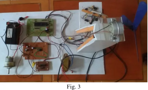
The wind turbine consists of 3 rotor blades which are made up of either plastic or galvanized iron sheet. A wind vane is used to detect the wind direction which is placed on a horizontal plate. Four IR sensors are placed in four directions with some angle. Depending upon the position of wind vane the IR sensor gets activated that means wind velocity is high in that direction. With the help of programmable microcontroller the wind turbine is aligned according to wind direction.
A DC motor is interfaced with microcontroller with the help of L293D motor driver. With the help of microcontroller DC motor is shifted in the direction in which the IR sensor is activated. The shaft of DC motor is connected to wind turbine shaft hence if the DC motor is shifted in the particular direction the DC generator also aligned in that direction.
Fig. 3
A. IR Sensors
The purpose of IR sensors is to provide information to the wind turbine about wind direction. A direction indicator which turns according to wind direction is placed on a horizontal plate. Whenever the direction indicator moves in the particular direction the IR sensors which is in that direction is getting activated by transmitting signal from IR transmitter to obstacle and then to IR reflector.
A DC motor is connected to the shaft of wind turbine. With the help of programmable microcontroller and L293D motor driver the dc motor will rotate in the direction IR sensor is activated. Four IR sensors are placed in four directions, for example the wind flow is from East direction the direction indicator turns in to the East direction then the IR sensor in the East direction getting in to on state then the dc motor with the help of microcontroller shifts the rotor present position (may be north, south, west) to east. Hence the rotor turns to the east direction and starts rotating. In this way wind tracking is done with the help of IR sensors without using any conventional methods
Fig. 4
B. Microcontroller
We used the 8-bit microcontroller from ATMEL (AT89S52). The microcontroller in our security system is used for sending signals to the auto dialer and buzzer alarm. A number is already stored in the EEPROM of the microcontroller. When a logic low signal appears at the pin 1 of the microcontroller, the number stored in the memory is sent to the auto dialer.
The AT89S52 provides the following standard features: 8Kbytes of Flash, 256 bytes of RAM, 32 I/O lines, three 16-bit timer/counters, six-vector two-level interrupt architecture, a full duplex serial port, on-chip oscillator, and clock circuitry. In addition, the AT89S52 is designed with static logic for operation down to zero frequency and supports two software selectable power saving modes.
[image:4.612.187.437.183.335.2]Technology (IJRASET)
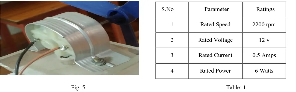
reset. [10]C. DC Generator
It is used to convert the mechanical energy of rotating wind turbine into electrical energy.DC generator used in our paper is permanent magnet dc generator as shown in figure and ratings of the dc generator.
[image:5.612.42.535.138.292.2]
Fig. 5 Table: 1
D. DC Motor
It is used to shift the wind turbine according to wind direction. The shaft of DC motor is connected directly to dc generator. By using L293D motor driver microcontroller is interfaced with DC motor. After receiving signal from microcontroller the DC motor shifts the wind turbine according to wind direction
Fig. 6 Table: 2
V. RESULTS AND DISCUSSIONS
A. Without Wind Tracking
Wind turbine is aligned in north direction and wind is blowing from north. As wind turbine is aligned in the North direction and wind is blowing from North side with a velocity of 10 m/s hence there is a generated voltage of 8volts
S.No
Wind Direction
Wind Velocity(m/s)
Generator speed(rpm)
Generator voltage(volts)
1 North 10m/s 1500rpm 8
2 South 0 m/s 0 rpm 0
3 East 0 m/s 0 rpm 0
[image:5.612.67.545.355.522.2]4 West 0 m/s 0 rpm 0
Table: 3
S.No Parameter Ratings
1 Rated Speed 2200 rpm
2 Rated Voltage 12 v
3 Rated Current 0.5 Amps
4 Rated Power 6 Watts
S.No Parameter Ratings
1 Rated Voltage 12v
2 Rated Current 500mA
Technology (IJRASET)
B. Wind turbine is aligned in north direction and wind blowing from East
Wind turbine is aligned in north direction and wind is blowing from east. As wind turbine is aligned in the North direction and wind is blowing from East side with a velocity of 10 m/s, hence there is no generation of voltage.
S.No Wind Direction Wind Velocity(m/s) Generator speed(rpm) Generator voltage(volts)
1 North 0 m/s 0 rpm 0
2 South 0 m/s 0 rpm 0
3 East 10 m/s 0 rpm 0
4 West 0 m/s 0 rpm 0
Table: 4
C. With Wind tracking
If the wind turbine is aligned in north direction and wind blowing from east:
From the results it is clear that even though wind is blowing from one direction and the turbine positioning is in another direction by wind tracking the turbine will align according to wind position and starts rotating and produces voltage
S.No Wind Direction Wind Velocity(m/s) Generator speed(rpm) Generator voltage(volts)
1 North 0 m/s 0 0
2 South 0 m/s 0 rpm 0
3 East 10 m/s 1500 rpm 8
4 West 0 m/s 0 rpm 0
Table: 5
D. Voltage generated with different materials
Different types of materials like plastic, galvanized iron sheet are used for designing of wind plates to increase the speed of the turbine. So, that the generated voltage will be increased.
Table: 6
S.No Material
Used Wind Velocity(M/S) Wind Turbine Speed(Rpm) Generated Voltage(Volts)
1 Plastic 10 1800 10
2 Galvanized
Technology (IJRASET)
VI. CONCLUSION
As existing wind turbines are unable to produce continuous power as wind varies continuously. The existing controlling techniques are having so many limitations and with that existing techniques we are getting lower efficiency and the output voltage from the wind turbine generator also varies continuously and it is effects the load so our aim is to obtain constant voltage. To overcome limitations of existing methods of wind tracking, in this paper we employed an IR sensors based wind turbine that changes its direction according to wind intensity and direction and increases the efficiency of wind turbine without producing any frictional losses.
To produce constant voltage we place a voltage regulator between DC generator and load to provide constant output voltage irrespective of input voltage. Hence this embedded sensor wind turbine with voltage regulator produces constant and continuous power and it does not cause any damages to the wind turbine components and helpful for the smoother operation of load by producing constant power.
REFERENCES
[1] Joshua Earnest and Tore Wizelius, “Wind Power Plants & Product Development” PHI learning Publishers, 2011.
[2] Shilpa Mishra, S.Chatterji, Shimi S.L, Sandeepshulka “Modeling and Control of Standalone PMSG WECS for Grid Compatibility at Varying Wind Speeds International Journal of Engineering Trends and Technology (IJETT) – Volume17 Number 10–Nov2014
[3] PP. Vinod Kumar, L.VenkatasureshKumar, Ravipudi.Sudhir “POWER CONTROL OF GRID CONNECTED PMSG WIND ENERGY SYSTEM Vol. 2, Issue 10, October 2013.
[4] Liuchen Chang “Wind Energy Conversion Systems”, IEEE Canadian Review - spring / Printemps, pp. 12- 16, 2010.
[5] Abdel Aitouche and Elkhatib Kamal, “Intelligent Control of Wind Energy Conversion Systems”, ISBN: 978-953- 307-467-2, InTech, 2011.
[6] Pena, R., Clare, J.C., and Asher, G.M. 1996. Doubly fed induction generator using back-to back PWM converters and its application to variable-speed wind- energy generation. IEEE Proc.- Electr. Power Appl., Vol. 143, No. 3.
[7] Akdag, S. A., and Guler, O. 2010. Comparison of Wind Turbine Power Curve Models. Sousse, Tunisia: International Renewable Energy Congress.
[8] Bharanikumar, R., Yazhini, A. C., and Kumar, A. N.2010. Modeling and Simulation of Wind Turbine Driven Permanent Magnet Generator with New MPPT Algorithm. Asian Power Electronics Journal, vol. 4,No:2.
[9] Melicio, R., Mendes, V. M. F., and Catalao, J. P. S. 2009.Computer Simulation of Wind Power System Power Electronics and Transient Stability Analysis. Kyoto, Japan: International Conference on Power System Transient (IPST2009).
[10] S.Boopathi, A.Prabahakaran, Dr.N.SuthanthiraVanitha “ Embedded based wind mill using object sensor” International Journal Of Innovative Research In Electrical, Electronics, Instrumentation And Control Engineering Vol. 2, Issue 8, August 2014.
AUTHORS PROFILE
B. ShanmukhaRao pursuing B.Tech in Electrical and Electronics Engineering at Pragati Engineering College, Surampalem, East Godavari District Andhrapradesh. His areas of interests are renewable energy sources, Electrical machines
D. Rajesh pursuing B.Tech in Electrical and Electronics Engineering at Pragati Engineering College, Surampalem, East Godavari District Andhrapradesh. His areas of interests are renewable energy sources, Power Electronics.