I N T E R N A T I O N A L J O U R N A L F O R RE S E A R C H I N A P PL I E D SC I E N C E
AN D E N G I N E E R I N G T E C H N O L O G Y (I J R A S E T)
Page 190
Thermal Performance Analysis of A Circular
Tube Using Vortex Rings at Various Angle and
Pitch Ratio
Eknath.Kurhe1, Sameer Bhosale2
M.M.I.T1, Modern C.O.E2. Department of Mechanical Engineering
University of Pune Maharashtra, India.
Abstract: The influence of inclined vortex rings (VR) on heat transfer augmentation in a uniform heat-fluxed tube has been investigated experimentally. In the present work, thevortex rings were mounted repeatedly in the tube with various angle (250,300,350) and geometry parameters of the VR, three relative pitch ratios (PR = P/D = 2, 1 and 0.5) and at constant relative ring blockage ratios (BR = b/D = 0.2). Air was employed as the test fluid in the tube for the Reynolds number from 12000 to 24,500. The aim at using the VRs is to create counter-rotating vortices inside the tube to help increase the turbulence intensity as well as to convey the colder fluid from the core regime to the heated-wall region. The experimental results show a significant effect of the presence of the VRs on the heat transfer and pressure loss over the smooth tube. The larger BR value provides higher heat transfer and pressure loss than the smaller.
The Nusselt number is maximum for vortex ring angle 350, but due to the large increase in the friction factor, thermal performance decreases. However, the VR at BR = 0.2 and PR = 0.5 with 300yields the best thermal performance.
Keywords: Heat transfer,inclined vortex ring,Circular Tube, Turbulators, Nusselt number.
I. INTRODUCTION
Heat transfer augmentation techniques are needed in heat exchanger systems to enhance heat transfer rate and improve their thermal performance. The techniques for heat transfer augmentation can be divided into two main
groups. One is the active method requiring extra external power sources such as mechanical aids, surface-fluid
Vibration, injection and suction of the fluid, jet impingement, and electrostatic fields. The other is the passive method that requires no external power for the systems. In general, the passive method is more popular and it includes a surface coating, wavy surfaces, rough and extended surfaces, convoluted (twisted) tube, additives for liquid and gases, turbulators (coiled wire and conical ring) and vortex/swirl generators. Most inserted devices mentioned above that form an important
group of the passive augmentation technique, are frequently used to generate vortex/swirl flow in the thermal system. Insertion of vortex/swirl generators in a circular tube is a simple technique for enhancing theconvective heat transfer coefficient on the tube side of a heat exchanger due to their advantages of easy fabrication and operation as well as low maintenance. In addition, the performance of those turbulators or vortex generators strongly depends on their geometries. There are many types of vortex generators employed in the heat exchanger ducts/tubes such as helical/twisted tapes [1-3], coiled wires [4-6], circular/twisted-rings [7,8] and angle-finned tapes [9,10].
flow region. Promvonge [13] studied the insertion effect of the conical ring arrangements, namely, converging conical ring, diverging conical ring, and converging-diverging conical ring on the heat transfer rate, friction factor and thermal performance in a round tube. The study showed that the diverging conical ring offered higher thermal performance than the converging and converginge diverging ones. Durmus [14] investigated the effect of angle arrangement of the conical-ring type turbulators on the heat transfer and friction loss. The investigated results revealed that heat transfer rate as well as friction factor increased with the increase in the conical-ring angle. Promvonge and Eiamsa-ard [15] examined the combined effect of the conical-ring and twisted-tape for heat transfer enhancement in a circular tube. As reported, the use of the conical-ring in common with the twisted-tape provided an average heat transfer rate up to 10% over that of the conical-ring alone. Taslim et al. [16] conducted a measurement of the heat transfer in a V-ribbed square channel with three relative rib height ratios (e/ D = 0.083, 0.125 and 0.167) at a fixed P/e = 10 using a liquid crystal technique. Various staggered rib configurations were studied, especiallyfor the angle of 450and experimental data showed a significant increase in average Nusselt number with increasing the e/D value. Chandra et al. [17] studied the heat transfer behaviors in a square channel with continuous ribs on four walls where ribs were placed superimposed on walls. They found that the heat transfer increases with the increment in the number of ribbed walls and with reducing Reynolds number while the friction factor increases with both cases.
Apart from experimental investigations, the numerical studies on heat transfer enhancement by means of the circular ring turbulators were also reported [18,19]. Ozceyhan et al. [18] numerically studied effect of space between the circular rings on heat transfer rate and friction factor. Similarly, Akansu [19] numerically investigated the effect of pitch spacing of porous rings and demonstrated that the heat transfer rate and friction factor increased with decrement of the ring spacing. Kwankaomeng and Promvonge [20], and Promvonge et al. [21] studied numerically the laminar periodic flow over 300 and 450 angled baffles repeatedly mounted only on one wall of a square channel, respectively. They noted that the heat transfer enhancement for the 450 angled baffle with BR = 0.4 was about 2-3 fold higher than that for the 900baffle while the friction loss was some 10-25% lower. In addition, they found that a single stream wise main vortex flow created by the angled baffles/fins can help to induce impingement flows on the upper, lower and baffle trailing end walls of the channel. The
appearance of the vortex induced impingement (VI) led to drastic increase in the thermal performance of the channel. In comparison, the 300baffle/fin performs better than the 450one due to lower pressure losses.
From the literature review cited above, the use of wire coil/twisted tape inserts in the tube may not be suitable due to lower strength of the vortex flow, leading to thermal performance in a range of 0.7 to 1.1.
Promvonge et al. [22, 23] again investigated numerically the laminar flow structure and thermal behaviours in a square channel with 300 and 450 inline baffles on two opposite walls. Two stream wise counter rotating vortex flows were created along the channel and VI jets appeared on the upper, lower and baffle leading end walls while the maximum thermal performance was found for the 300inline baffle case. The works in Refs. [20-25] triggered the present work to investigate the heat transfer enhancement in a tube inserted with 300inclined VRs. In a square duct with wall roughened by repeated angled-baffles (or fins), the baffle-induced secondary flows (or vortex flows) accompanied by enhanced turbulence intensity provide a drastic increase in heat transfer due to the VI effect as reported in Refs.[21, 22, 24].
In the present work, another type of inserted devices has been developed by insertion of inclined VRs into a circular tube.
The present inserted device has been developed from a combination of the merits of baffle, winglet and twisted tape tabulators.
This means that the inserted device will provide a drastically high heat transfer rate like baffles, swirl/vortex flow as winglets and ease of practical use like twisted tapes. Therefore, a newly 300 inclined VR insert is proposed and expected to provide higher thermal performance than the wire coil/twisted tape inserts due to the VI effect. The experimental results using air as the test fluid for the VR inserted tube are presented for turbulent flows in a Reynolds number range of 12000 to 24,500 in the current study.
II. EXPERIMENTAL SETUP
IN T E R N A T I O N A L J O U R N A L F O R R E S E A R C H I N A P P L I E D S C I E N C E
AN D E N G I N E E R I N G T E C H N O L O G Y (IJ R A S E T)
ring given in Fig. 2 were connected to each other by insertion of two small straight steel rods into
the hole on both sides of the VRs. The VRs with (BR = b/D = 0.2) and pitch ratios (PR = P/D = 0.5) were inserted into the tube by wall-attached position. The tube was heated by nicrome wire, band type 400W electrical heater to provide a uniform heat flux boundary condition. The electrical output power was controlled by a variac transformer to obtain a constant heat flux along
the entire length of the test section. The outer surface of the test tube was well insulated to minimizeconvective heat loss to surroundings. The inlet and outlet temperatures of the bulk air were measured at certain points with a data logger in conjunction with the RTD thermocouples were tapped equally along the local top and side walls of the outer tube surface. The inlet air from a high pressure blower was directed through the orifice meter and passed to thetested section fitted
Fig.1 Schematic diagram of experimental apparatus
repeatedly with 250,300and350inclined VRs. The air flow rate was measured by an orifice meter, built according to ASME standard [26]. Manometric fluid was used in a U-tube manometer with specific gravity (SG) of 0.61 to ensure reasonably accurate measurement of pressure drop. Also, the low pressure drop of the tested tube was measured with an inclined U-tube manometer. The volumetric air flow rates from the blower were adjusted by varying flow control valve. During the experiments, the bulk air was heated by an adjustable electrical band heater wrapping along the test section.
Fig.3: Actual view of VRs
III. DATA COLLECTION AND ANALYSIS
A. Heat Transfer Calculations:
In the present work, air is the test fluid. The steady state heat transfer rate is assumed to be equal to the heat loss in the test tube:
Qair = Qconv (1)
in which
Qair= ṁCp air (To - Ti) = VI - heat losses(2)
The heat supplied by electrical heater in the test tube is found to be 3-5% higher than the heat absorbed by the fluid for thermal equilibrium test due to convection and radiation heat losses from the test tube to surroundings. Thus, only the heat transfer rate absorbed by the fluid is taken for internal convective heat transfer coefficient calculation. The convection heat transfer from the test tube can be written by
Qconv= hA (Ts –Tb)
(3) in which
Tb= (To- Ti) / 2
(4) Ts= ∑Ts/ 5
(5)
Where for a constant heat flux, the average surface temperature Tscan be calculated from 5 points of the local surface temperatures, Ts, lined equally apart between the inlet and the exit on the top and the side walls of the test tube. The average heat transfer coefficient, h and the average Nusselt number, Nu are estimated as follows:
h = ṁCp air (To–Ti) / A (Ts–Tb) (6)
Nu = hD / k (7)
The Reynolds number is given by
Re = UD / υ (8)
Friction factor, f, can be written as
f = ∆
/ (9)
in which U is mean air velocity in the tube. All thermo-physical properties of air are determined at the overall bulk air temperature from Eq. (4).
The thermal enhancement factor, TEF, defined as the ratio of the,h of an augmented surface to that of a smooth surface, h0, at an identical pumping power:
= = = (10)
IV. RESULT AND DISCUSSION
A. Verification for smooth tube:
The present experimental results on heat transfer and friction characteristics in a smooth wall tube are first validated in terms of Nusselt number and friction factor. The Nusselt number and friction factor obtained from the present smooth tube are, respectively, compared with the correlations of Dittus Boelter for Nusselt number,
and of Petukhov for friction factor found in the open literature [28] for turbulent flow in ducts.
Correlation of Dittus Boelter:
I N T E R N A T I O N A L J O U R N A L F O R RE S E A R C H I N A P PL I E D SC I E N C E
AN D E N G I N E E R I N G T E C H N O L O G Y (I J R A S E T)
Page 194 Correlation of Petukhov,
= (0.79 ln Re –1.64) - 2 (12)
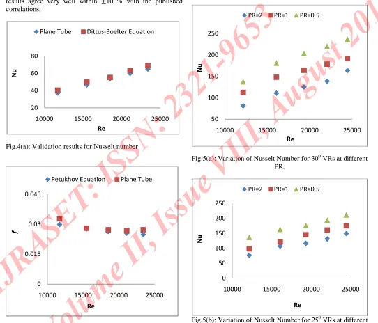
Fig. 4(a) & (b) shows a comparison of the Nusselt number and friction factor obtained from the present work with those from correlations of Eqs. (11) and (12). In the figure, the present results agree very well within ±10 % with the published correlations.
Fig.4(a): Validation results for Nusselt number
Fig.4(b):Validation results for friction factor
B. Effect of angle of inclination
The experimental results on heat transfer and friction characteristicsin a uniform heat-fluxed tube fitted with VRs at three relative angle 250,300 and 350and relative ring Pitch ratios (PR = 2, 1, 0.5)
Fig.5(a): Variation of Nusselt Number for 300VRs at different PR.
Fig.5(b): Variation of Nusselt Number for 250VRs at different PR.
20 40 60 80
10000 15000 20000 25000
Re
Plane Tube Dittus-Boelter Equation
0 0.015 0.03 0.045
10000 15000 20000 25000
Re
Petukhov Equation Plane Tube
50 100 150 200 250
10000 15000 20000 25000
Re
PR=2 PR=1 PR=0.5
0 50 100 150 200 250
10000 15000 20000 25000
Re
[image:6.612.33.575.194.658.2]Fig.5(c): Variation of Nusselt Number for 350VRs at different PR.
Fig.6(a): Variation friction factor for 300VRs at different PR
with constant blockage ratio (BR=0.5) are presented in the form of Nusselt number and friction factor as displayed in Fig. 4a and b, respectively. In Fig. 4a, it is found that the Nusselt number is higher at an angle 350, apart from the Re values. The variation of friction factor with Reynolds number for different angle is presented in Fig.6(a),(b) and (c). It is observed that friction factor gradually reduced with rise in
Reynolds number and is maximum for VR angle 350 and minimum for 250VRs.
Fig.6(b): Variation of friction factor for 250VRs at different PR
Fig.6(c): Variation of friction factor for 350 VRs at different PR
C. Effect of Pitch ratio (PR) 0
50 100 150 200 250 300
10000 15000 20000 25000
Re
PR=2 PR=1 PR=0.5
0 0.2 0.4 0.6 0.8 1 1.2 1.4
10000 15000 20000 25000
Re
PR=2 PR=1 PR=0.5
0 0.2 0.4 0.6 0.8 1 1.2
10000 15000 20000 25000
Re
PR=2 PR=1 PR=0.5
0 0.2 0.4 0.6 0.8 1 1.2 1.4 1.6
10000 15000 20000 25000
Re
I N T E R N A T I O N A L J O U R N A L F O R RE S E A R C H I N A P PL I E D SC I E N C E
AN D E N G I N E E R I N G T E C H N O L O G Y (I J R A S E T)
Page 196 The variation in Nusselt number & friction factor is shown in figure 5 (a), (b), (c) and 6 (a), (b), (c). The effects of four pitch ratios (PR =0.5, 0.10 and 0.20) forvarious angles (250,300and 350 ) of VR inserts on heat transfer rate and friction loss in terms ofNusselt number and friction factor are also depicted in Figs. 5 and 6,
respectively. It can be observed in Fig. 4(a),(b) and (c) that the Nusselt numberincreases with reducing the PR, apart from Re values. This is
because the VR with smaller PR interrupts frequently the developmentof the boundary layer of the fluid flow and also increasesthe turbulence intensity of the flow. Importantly, for BR = 0.2, theVR at PR = 0.5 shows higher heat transfer rate than the one atPR =1.0 and 2.0.The Nu values at 250, 300 and350 are in the range of 76.33-149.2, 98.3-175.11 and136.32-211.33, 81.2-163.8, 112.67-191.320 and 137.21-236.21, 83.34-162.12, 112.32-181.21 and 155.12-242.43 for PR=2.0, 1.0 and 0.5 respectively.
In Fig. 5(a),(b) and (c),the friction factor for the VR at PR = 0.5 is much higher than that forthe one at smaller PR. The friction factor tends to reduce with theincrement of PR and shows a rapid decrease for PR = 0.5 to1.0 ascan be seen in Fig. 5(a), (b) and (c). At BR = 0.2, the friction factor for the VRswith PR = 0.5 is, respectively, found to be around 48%,and 73%higher than that for the ones with PR =1.0 and 2.0.For VRs angle 25, 30 and 35 the friction factor ranges from 0.191-0.257, 0.415-0.526 and 0.819-1.04, 0.248-0.319, 0.473-0.596, and 0.921-1.157, 0.298-0.367, 0.693-0.811 and 1.26-1.52.
To describe the physical nature of heat transfer enhancement,the field synergy principle is introduced. According to the fieldsynergy principle [29-31], the better the synergy between velocityfield and temperature field is, the higher the heat transferaugmentation will be at the same boundary conditions of the velocityand temperature. The three heat transfer enhancementmechanisms [29] were proposed, the decreasing the thermalboundary layer, the increasing of the flow interruption and theincrease in velocity gradient near the heated wall, all result in thereduction of the intersection angle between the velocity and thetemperature field. Therefore, the use of the VRs in the present workcan trigger the three mechanisms to work because of the VI effectthat induces the impingement flows on the heatedwall. This
meansthat the intersection or synergy angle between the impingementflow and temperature gradient direction with the VRs is muchsmaller than that without the VR.
D. Performance evaluation:
Fig 7(a), (b) and (c) shows the variation of the thermal performance enhancement factor (TEF) with Reynolds number.
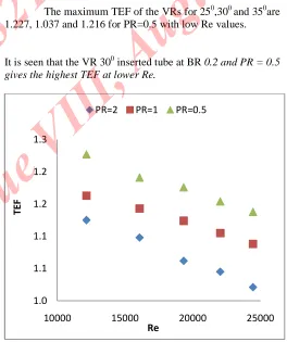
For all, the data of Nusselt number and friction factor ratios obtained from the correlations are compared at an identical pumping power condition. In the figure, the TEF found to be above unity tends to reduce with the increase in Re for 300 and 350. But it is less than one for 250. Nusselt number for 350 VRs is highest but it also increases the friction factor proportionally and hence decreasing TEF.
The maximum TEF of the VRs for 250,300 and 350are 1.227, 1.037 and 1.216 for PR=0.5 with low Re values.
It is seen that the VR 300inserted tube at BR 0.2 and PR = 0.5 gives the highest TEF at lower Re.
Fig.7 (a): Variation in TEF for 300VRs at different PR 1.0
1.1 1.1 1.2 1.2 1.3
10000 15000 20000 25000
Re
[image:8.612.303.567.304.619.2]Fig.7(b): Variation in TEF for 250VRs at different PR
Fig.7(c): Variation in TEF for 250VRs at different PR
V. CONCLUSIONS
An experimental study has been conducted to examine the heattransfer and flow friction characteristics in a round tube insertedwith the inclined VRs at different angles (250, 300 and 350) different BRs with constant PR (0.5) for the turbulentflow, Reynolds number from 12000 to 24,500. The presence of theVRs at BR = 0.2, PR = 0.5 causes a much high pressure drop increase,but also provides a considerable heattransfer augmentation in the tube. The Nusseltnumber of the VR inserted tube shows an increasing trend with therise in BR and Re values but with the reduction of PR. The TEFs ofthe inserted tube are above unity for 300 and 350 VRs and tend to decrease with the increment in Re. The 300VR at BR= 0.2 and PR=0.5 yields the highest TEF of about 1.227 at lower Reynoldsnumber.
VI. NOMENCLATURE
A heat transfer surface area, m2 b ring width, m
BR relative ring width or blockage ratio = b/D, e/D Cp,air specific heat capacity of air, kJ /kgK
D diameter, m
e rib or baffle height, m f friction factor
h mean heat transfer coefficient, W/ m2/K I current, A
k thermal conductivity of air, W/m K L length of test tube, m
ṁ mass flow rate, kg/s Nu Nusselt number Q heat transfer rate, W P pitch length of VR, m DP pressure drop, Pa
PR relative ring pitch or pitch ratio =P/D Pr Prandtl number
Re Reynolds number T temperature, K
TEF thermal performance enhancement factor t thickness of test tube, m
U mean axial velocity, m/ s V voltage, V
VI vortex-induced impingement VR vortex ring
0.90 0.92 0.94 0.96 0.98 1.00 1.02 1.04 1.06
10000 15000 20000 25000
Re
PR=2 PR=1 PR=0.5
1.00 1.05 1.10 1.15 1.20 1.25
10000 15000 20000 25000
Re
I N T E R N A T I O N A L J O U R N A L F O R RE S E A R C H I N A P PL I E D SC I E N C E
AN D E N G I N E E R I N G T E C H N O L O G Y (I J R A S E T)
Page 198 REFERENCES
[1] S. Eiamsa-ard, P. Promvonge, Heat transfer characteristics in a tube fitted withhelical screw-tape with/without core-rod inserts, Int. Commun. Heat MassTransfer 34 (2) (2007) 176-185.
[2] S. Eiamsa-ard, S. Pethkool, C. Thianponge, P. Promvonge, Turbulent flow heattransfer and pressure loss in a double pipe heat exchanger with louvered stripinserts, Int. Commun. Heat Mass Transfer 35 (2008) 120-129.
[3] S. Eiamsa-ard, C. Thianponge, P. Eiamsa-ard, P. Promvonge, Convective heattransfer in a circular tube with short-length twisted tape insert, Int. Commun.Heat Mass Transfer 36 (2009) 365-371.
[4] P. Promvonge, Thermal augmentation in circular tube with twisted tape andwire coil turbulators, Energy Convers. Manage. 49 (2008) 2949-2955.
[5] P. Promvonge, Thermal performance in circular tube fitted with coiled squarewires, Energy Convers. Manage. 49 (5) (2008) 980-987.
[6] P. Promvonge, Thermal enhancement in a round tube with snail entry andcoiled-wire inserts, Int. Commun. Heat Mass Transfer 35 (2008) 623-629.
[7] V. Kongkaitpaiboon, K. Nanan, S. Eiamsa-ard, Experimental investigation ofconvective heat transfer and pressure loss in a round tube fitted with circularringturbulators, Int. Commun. Heat Mass Transfer 37 (2010) 568-574.
[8] C. Thianpong, K. Yongsiri, K. Nanan, S. Eiamsa-ard, Thermal performanceevaluation of heat exchangers fitted with twisted-ring turbulators, Int. Commun.Heat Mass Transfer 39 (2012) 861-868.
[9] P. Promvonge, S. Skullong, S. Kwankaomeng, C. Thiangpong, Heat transfer in
square duct fitted diagonally with angle-finned tape e part 1: experimentalstudy, Int. Commun. Heat Mass Transfer 39 (5) (2012) 617-624.
[10] P. Promvonge, S. Skullong, S. Kwankaomeng, C. Thiangpong, Heat transfer in
square duct fitted diagonally with angle-finned tape e part 2: numericalstudy, Int. Commun. Heat Mass Transfer 39 (5) (2012) 625-633.
[11] K. Yakut, B. Sahin, S. Canbazoglu, Performance and flow-induced vibrationcharacteristics for conical-ring turbulators, Appl. Energy 79 (2004) 65-76.
[12] K. Yakut, B. Sahin, Flow-induced vibration analysis of conical rings used ofheat transfer enhancement in heat exchanger, Appl. Energy 78 (2004) 273-288.
[13] P. Promvonge, Heat transfer behaviors in round tube with conical ring inserts,Energy Convers. Manage. 49 (2008) 8-15.
[14] A. Durmus, Heat transfer and exergy loss in cut out conical turbulators, Energy
Convers. Manage. 45 (2004) 785-796.
[15] P. Promvonge, S. Eiamsa-ard, Heat transfer behaviors in a tube with combined
conical-ring and twisted-tape insert, Int. Commun. Heat Mass Transfer 34(2007) 849-859.
[16] M.E. Taslim, T. Li, D.M. Kercher, Experimental heat transfer and friction inchannels roughened with angled, V-shaped, and discrete ribs on two oppositewalls, ASME J. Turbomach. 118 (1996) 20-28.
[17] P.R. Chandra, C.R. Alexander, J.C. Han, Heat transfer and friction behaviour inrectangular channels with varying number of ribbed walls, Int. J. Heat MassTransfer 46 (2003) 481-495.
[18] V. Ozceyhan, S. Gunes, O. Buyukalaca, N. Altuntop, Heat transfer enhancementin a tube using circular cross sectional rings separated from wall, Appl. Energy85 (2008) 988-1001.
[19] S.O. Akansu, Heat transfers and pressure drops for porous-ring turbulators in acircular pipe, Appl. Energy 83 (2006) 280-298.
[20] S. Kwankaomeng, P. Promvonge, Numerical prediction on laminar heattransfer in square duct with 300angled baffle on one wall, Int. Commun. HeatMass Transfer 37 (2010) 857-866.
[21] P. Promvonge, S. Sripattanapipat, S. Tamna, S. Kwankaomeng, C. Thianpong,Numerical investigation of laminar heat transfer in a square channel with 450inclined baffles, Int. Commun. Heat Mass Transfer 37 (2010) 170-177. [22] P. Promvonge, W. Jedsadaratanachai, S. Kwankaomeng, Numerical study oflaminar flow and heat transfer in square channel with 30_ inline angled baffleturbulators, Appl. Therm. Eng. 30 (11-12) (2010) 1292-1303.
[23] P. Promvonge, S. Sripattanapipat, S. Kwankaomeng, Laminar periodic flow and
heat transfer in square channel with 450inline baffles on two opposite walls,Int. J. Therm. Sci. 49 (2010) 963-975.
[24] P. Promvonge, W. Changcharoen, S. Kwankaomeng, C. Thianpong, Numericalheat transfer study of turbulent square-duct flow through inline V-shapeddiscrete ribs, Int. Commun. Heat Mass Transfer 38 (10) (2011) 1392-1399.
[25] P. Sriromreun, C. Thianpong, P. Promvonge, Experimental and numericalstudy on heat transfer enhancement in a channel with Z-shaped baffles, Int.Commun. Heat Mass Transfer 39 (2012) 945-952.
[27] ANSI/ASME, Measurement Uncertainty, 1986. PTC 19, 1e1985. Part I.
[28] F. Incropera, P.D. Dewitt, Introduction to Heat Transfer, fifth ed., John Wiley &Sons Inc, 2006.
[29] W.Q. Tao, Y.L. He, A unified analysis on enhancing single phase convectiveheat transfer with field synergy principle, Int. J. Heat Mass Transfer 45 (2002)4871-4879. [30] J.M. Wu, W.Q. Tao, Investigation on laminar convection heat transfer in finand-tube heat exchanger in aligned arrangement with longitudinal vortexgenerator from the view point of field synergy principle, Appl. Therm. Eng. 27(2007) 2609-2617.