Fault Recovery Using Scan Chain Based
Approach Technique
M.Sridevi1, IEEE MEMBER, Ms.D.Devi2
1PG Student, Department of ECE, 2Assistant Professor, Department of ECE
Sri Krishna College of Engineering and Technology, Coimbatore.
Abstract-Recent applications of all embedded system will get failure due to multiple faults occurring in the system. This fault should be detected and corrected simultaneously while running the system. In practise we use a scan chain based Triple modular redundancy (TMR) approach technique. It is very expensive and requires three times more hardware resources. This paper explores the application of reduced-precision redundancy (RPR) to the problem, the metric used to evaluate the effectiveness of RPR is the bit error rate (BER) achieved by the FPGA. RPR is applied to a real FPGA-based system and is validated with extensive fault injection experiments. These method can be achieved by using reduced scan chain based multiple fault error recovery (RSCMFER) method
Index Terms— Roll-Forward Error Recovery, FIR filter, Triple Modular Redundancy (TMR) FPGA, Fault detection
I. INTRODUCTION
A traditional TMR system consisting of three redundant modules and a voter at the modules outputs has some shortcomings that should be addressed in order to be employed in safety critical applications. A major short coming of the traditional TMR is its inability to cope with TMR failures.TMR failure refers to a failure in a TMR system caused by multiple faulty modules or a faulty voter. For long-term applications, the absence of appropriate recovery mechanisms significantly will increase the probability of TMR failure occurrence. TMR should be equipped with a transient error recovery technique. Most of the previous TMR-based error recovery techniques proposed so far exploit retry mechanisms. These techniques, however, are not suitable for tight deadline applications, as the recomputation may result in a task completion after its deadline. Retry based error recovery mechanisms, roll forward recovery mechanisms are efficient to be used in tight deadline applications as no recomputation is needed. ScTMR uses a roll-forward approach and employs the scan chain implemented in the circuits for testability purposes to recover the system fault-free state. Although ScTMR significantly reduces the probability of TMR failures, it suffers from two major shortcomings. First, ScTMR cannot recover a single faulty module in the TMR system in the presence of latent faults. A fault is referred to as latent if it is not propagated to the system outputs but does cause a mismatch between the states of the TMR modules. Second, ScTMR is unable to recover the system if multiple faults are simultaneously manifested to the outputs of two modules.
In this paper, we present a scan-chain-based roll-forward error recovery technique for TMR-based systems, which addresses the shortcomings of ScTMR. The proposed technique,called scan chain-based multiple error recovery TMR (SMERTMR), has the ability to locate and remove latent faults in TMR modules as well as to recover the system from multiple faults affecting two TMR modules. To the best of our knowledge, SMERTMR is the first roll-forward error recovery technique for a TMR-based system that has the capability of error recovery in the presence of multiple latent faults as well as two faulty modules. The main idea behind SMERTMR is to reuse the available scan chains devoted for testability purposes in order to compare the internal states of TMR modules to locate and restore the correct state of faulty modules using the state of non faulty modules. In case of permanent faults, the faulty module is disregarded and the system degraded to master/checker (M/C) configuration. Nevertheless, the offline testability characteristics of the system are preserved. As compared to other TMR-based recovery techniques, SMERTMR has negligible area overhead, as it reuses the available resources within the circuit.
II. SMERTMR SYSTEM
140
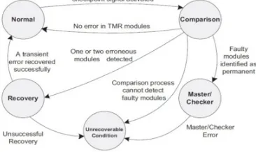
Comparison mode is responsible for the bit by bit comparison of the data in the modules. This mode will find out the faulty modules at the end of comparison operation. The information about the faulty modules is then passed to the recovery mode, which initiates the recovery operation and restores the system states. Any failure during the operation will end with unrecoverable condition. Then all systems are halted. Initially the system is in the normal mode of operation. When an error is detected by the voter or when a check point signal is activated, the system switches to comparison mode of operation. After comparison, if no system is found faulty, then the control will go to the normal mode. If it fails to detect the fault, then it will go to the unrecoverable state. If one or two erroneous modules are detected, then the recovery mode of operation is done. After successful recovery, it will go to normal mode. If it fails to recover the system the control passes to unrecoverable state. If all the modules are faulty, then also the system goes into the unrecoverable condition.
B. Comparison Mode
In this mode, the SMERTMR controller enables the scan chains of the SMERTMR modules. The internal states of the modules are scanned out through the SCO pin of the scan chain flip flops. Each of the bits is compared using XOR gates connected to the outputs of each pair of modules. At the end of comparison process, the faulty module is located.
C. Recovery Mode
In this mode, the SMERTMR controller enables the scan chains of the SMERTMR modules. The SCI signal of fault-free modules is connected to the SCO signal of the same module. In addition, the SCI signal of the faulty module is connected to
[image:3.612.202.385.334.443.2]the SCO of one of the fault-free modules. Thus the recovery of the faulty module is done.
Fig 1: State diagram of SMERTMR
III. FAULT DETECTION IN SMERTMR
Fig.2: SMERTMR in comparison mode
Whenever a mismatch is detected, the corresponding counter is incremented by one unit. Using this configuration, counter ij will contain the number of mismatches between modules i and j after Lsc clock cycles. The Fault Locator Unit (FLU) detects the faulty module using the fault module detection algorithm. The FLU stores the faulty module number in the Faulty Modules Register (FMR). In the SMERTMR technique, upon completion of the comparison mode, the fault locater unit (FLU) will determine the faulty modules. Algorithm 1 outlines how faulty modules are detected by the FLU. As can be seen, if all counters become zero, there is no faulty module and consequently the system returns to its normal mode. The condition statement in line 3 checks the existence of one faulty module. As discussed earlier, if there is only one faulty module, two out of three counters will have the same non-zero value while the third counter will be equal to zero. The condition statement in line 6 checks the existence of two faulty modules with no common faulty flip-flops. In the last two cases, the system enters the recovery mode to restore the correct state of the faulty modules using the state of the fault-free modules. If none of the previous conditions is valid, the system enters the unrecoverable condition . The FLU stores the faulty module numbers in a register named the faulty modules register (FMR).If FMR is equal to110, it means that modules I and II are faulty. This information is used by the SMERTMR controller during the recovery mode. It is worth mentioning that in SMERTMR, instead of directly comparing and voting the output of the three scan chains, we first make sure that we have correctly identified the fault-free module. If one directly compares and votes the outputs of the three scan chains, it is possible that two out of three replica flip-flops are erroneous and a wrong state is written back to all three modules. In this case, the system will continue to work in a wrong state. Such a condition is not acceptable in safety-critical applications.
A. Transient and Permanent Error Recovery Mechanisms
After the identification of fault-free and faulty modules by the FLU unit at the end of the comparison process, the system enters the recovery mode if there is one or two faulty modules in the system. Otherwise, it returns to the normal mode. In the recovery mode, the state of the faulty module is recovered by the state of fault-free modules using the employed scan chains.
Algorithm1:FaultyModules Detection Algorithm 1: if C ij = C ik = C jk = 0 then
2: next state ← Normal mode
142
8: FMR ← i, j 9: else
10: next state ←Unrecoverable condition 11: end if
The following will show how an SMERTMR system can detect and locate faulty modules by comparing the internal states of the system modules. Suppose that there is an SMERTMR system including three modules named i , j, and k. The system may be in the following four situations.
1) All modules are fault-free: In this case, all three counters will be equal to zero.
2) There is only one faulty module: Let us assume that module i is faulty and it contains x erroneous flip flops and the other modules, i.e., modules j and k are fault free. In this case, we will have counter ij = counter ik = x. Note that, since both modules j and k are fault-free, counter jk will be equal to zero (i.e., counter jk = 0). After extracting the number of mismatches, the system enters the recovery mode and the state of module i is recovered using the state of either modules j or k.
3) There are two faulty modules: Suppose that there are two faulty modules (e.g., modules i and j ) and one fault-free module (here, module k). Then counter ik = x, counter jk = y, and counter ij = x + y.
4) All modules are faulty: In this case, SMERTMR is not able to locate the faulty modules and it enters the unrecoverable condition.
IV. FAULT RECOVERY IN SMERTMR
Fig3: SMERTMR in recovery mode
In this mode, the SMERTMR controller enables the scan chains of the SMERTMR modules and configures the multiplexers as follows: The SCI signal of fault-free modules is connected to the SCO signal of the same module. In addition, the SCI signal of the faulty module is connected to the SCO of one of the fault- free modules., the value of the FMR register is used in the recovery mode to select the in-coming driver of the appropriate signal driver for the SCI signals. Using the configuration 8, the state of one of the fault-free modules is copied into the faulty modules after Lsc clock cycles. While shifting out the states of the modules in the recovery mode, similar to the comparison mode, they are also com- pared to find any mismatch due to faults occurring in the recovery process. During the recovery process, whenever a mismatch is detected and the corresponding counter value containing the number of mismatches is decreased by one unit. At the end of the recovery process, all counters should be zero. This is because, for each mismatch, the corresponding counter is incremented by one unit during the comparison process and is decremented by one unit during the recovery process. If either of the counters is nonzero at the end of the recovery process, it is indicative of another fault occurrence during the recovery process.
V. REDUCED FAULT RECOVERY METHOD
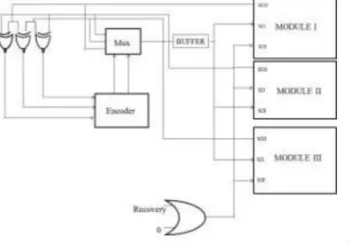
technique. I am presenting a scan-chain-based roll-forward error recovery technique for TMR-based systems, which addresses the shortcomings of all the existing methods. The proposed technique, called “Advanced error recovery for TMR systems”, has the ability to locate and remove latent faults in TMR modules as well as to recover the system from multiple faults affecting two TMR modules. The main idea is to reuse the available scan chains devoted for testability purposes in order to compare the internal states of TMR modules to locate and restore the correct state of faulty modules using the state of non-faulty modules. The proposed system can detect the error that occurs in a triple modular redundant system and to recover the same using minimum circuitry and less time. The system also aims to deal with the condition of multiple faults arriving at multiple modules. The system is actually a TMR system with an additional controller. The controller is the brain of the system. It is responsible for both error detection and recovery. This in turn reduces the time and area required. Comparison and recovery operations are done at the same time. After comparison of each bit, the mismatched bits are rewritten at the same time. After comparing each bit, the correct bit is written into a buffer, and the buffer output is in turn written into the module. This circuit is for the recovery operation of the modules. We can also include the counters and the Fault Locator modules from the SMERTMR, so that the faulty modules can be detected. But in real time systems we are unaware of the operations that are going inside the modules and we need an automatic recovery.
Figure 4: Block diagram of Reduced Error Recovery for TMR Systems
VI. REDUCED-PRECISION REDUNDANCY
RPR is a redundancy technique similar to TMR that requires less hardware overhead by using reduced- precision (RP) arithmetic in two of its three replicas. It takes advantage of the fact that RP Arithmetic can be a good estimate of computations that use higher precision. While TMR protects the entire circuit and provides an error-free output, RPR simply limits the error at the output of a module. RPR has an advantage over TMR when it is able to sufficiently limit the magnitude of the SEU-induced noise at a lower hardware cost.RPR is not suited to protect any type of circuitry as TMR is. Operations that can be approximated with less hardware than the standard module are candidate for RPR. RPR has, generally, been used to protect arithmetic operations.In addition the approximation and the decision hardware required to choose the final output must not exceed the cost of TMR, otherwise, any advantage of RPR is lost.
A. Implementation
[image:6.612.225.374.646.691.2]144
To determine the presence of an error, the decision block compares the outputs of the full-precision (FP) filter (FPout) with the outputs of the two RP filters (RP1out and RP2out) as follows:
if ( (FPout ¡RP1outj>Th) AND (RP1out =RP2out) output =>RP2out
else
output =>FPout.
In other words the FP output is used when no error is found or when the two RP modules disagree. Otherwise, the RP output is used, which provides an estimate of the correct FP output.RPR, in the form presented here, has two main parameters that can be adjusted. The impact of these parameter settings can be understood in terms of the arithmetic error
E²= FPtrue –RP true
where FPtrue and RPtrue are the outputs of the FP and RP filters, respectively, when no SEU is present. First, the size of the RP modules can be modified. In this paper the size of the RP filters is measured by the bit-width of the filter input signal, k. A larger RP filter gives a better estimate of the FP filter. This results in a better detection of errors in the FP filter and a lower E². A smaller RP filter is desirable because a smaller RP filter reduces the cost of mitigation. The second parameter for RPR is the threshold value Th. A threshold that is too small will cause the RP output to be chosen even when there are no errors in the FP module. To prevent this, Th ¸ max E²g is required. On the other hand, if Th is too large, the FP output is used even when there are significant errors in that module. In fact any error that is larger than maxf²g must be due to an upset in the system. Consequently, Th should be no greater than this value. In light of these bounds, Th is set equal to maxE²g
VII. RESULTS AND DISCUSSION
A. Result of SMERTMR
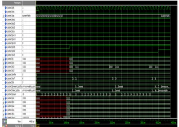
[image:7.612.215.396.565.694.2]In the comparison mode, the internal states of all TMR modules are shifted out using the scan chains and all module pairs (I/II, I/III, and II/III) are compared. There are three counters, namely, counter12, counter13, and counter23, to store the number of mismatches between each module pairs. For example, counter12 stores the number of mismatches between modules I and II. To this end, the SMERTMR controller enables scan chains of the SMERTMR modules and configures the multiplexers in such a way that the SCO signal in each module is connected to the SCI signal of the same module. During the shift operation, the internal states of the modules are compared using XOR gates. Whenever a mismatch is detected, the corresponding counter is incremented by one unit. While shifting out the states of the modules in the recovery mode, similar to the comparison mode, they are also com- pared to find any mismatch due to faults occurring in the recovery process. During the recovery process, whenever a mismatch is detected and the corresponding counter value containing the number of mismatches is decreased by one unit. At the end of the recovery process, all counters should be zero. This is because, for each mismatch, the corresponding counter is incremented by one unit during the comparison process and is decremented by one unit during the recovery process. If either of the counters is nonzero at the end of the recovery process, it is indicative of another fault occurrence during the recovery process. If the system enters the unrecoverable condition it will halts.
Fig7: Output of SMERTMR
[image:8.612.172.440.369.482.2]B. COMPARISION OF ScTMR AND SMERTMR USING XILIN4.3
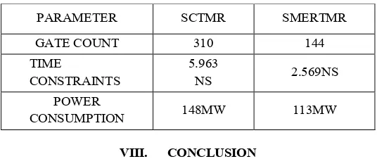
Table 1.Comparision
VIII. CONCLUSION
The system is designed for the detection and recovery of multiple errors in TMR based systems for safety critical applications. It reuses the scan chain flip flops for the process of error detection and recovery. Here the roll forward error recovery technique is used in which the state of the fault free module is copied in to the faulty one. This technique detects, locates, and corrects multiple faults affecting single and two faulty modules. The design is developed and compiled to VHDL net list .Here we compare the existing method ScTMR and our proposed method SMERTMR with XILINX ISE 13.2
IX. FUTURE WORK
The advanced error recovery technique recovers multiple errors that occur in a TMR system more efficiently .The VHDL code for the same is written and simulated using Xilinx ISE Design Suite 13.2.The system then detects the faulty modules, here modules 1 and 2, and they are recovered. At the end of recovery operation the voter output has become high
REFERENCES
[1] K. G. Shin and H. Kim, (1994) “A time redundancy approach to TMR failures using fault-state likelihoods,” IEEE Trans. Comput., vol. 43, no. 10, pp.1151– 1162,
[2] Manuel G. Gericota, Gustavo R. Alves,(2005), “A Self-Healing Real-Time System Based on Run-Time Self-Reconfiguration”, Computer, vol. 38, no. 2, pp. 43
PARAMETER SCTMR SMERTMR GATE COUNT 310 144 TIME
CONSTRAINTS
5.963
NS 2.569NS POWER
©IJRASET 2015: All Rights are Reserved
146
[6] Omar Hiari, Waseem Sadeh, and Osamah Rawashdeh(2012), “Towards Single Chip Diversity TMR for Automotive Applications,” Volume: 43 , Issue: 6,Page(s): 2742 – 2750.
[7] J. A. Abraham and D. P. Siewiorek, (1974) “An algorithm for the accurate reliability evaluation of triple modular redundancy networks,” IEEETrans. Comput., vol. 23, no. 7, pp. 682–692
[8] I. Koren and S. Y. H. Su(1979), “Reliability analysis of N-modular redundancy systems with intermittent and permanent faults,” IEEE Trans. Comput., vol. 28, no. 7, pp. 514–520, Jul.
[9] M. Zhang, S. Mitra, T. M. Mak, N. Seifert, N. J. Wang, Q. Shi, K. S.Kim, N. R. Shanbhag, and S. J. Patel, (2006) “Sequential element design with built-in soft error resilience,” IEEE Trans. Very Large Scale Integr.(VLSI) Syst., vol. 14, no. 12, pp. 1368–1378
[10] F. L. Kastensmidt, L. Sterpone, L. Carro, and M. S. Reorda., (2005) “On the optimal design of triple modular redundancy logic for SRAM-based FPGAs,” in Proc. Design Autom. Test Eur. Conf. Exhibit, pp.1530–159