Evaluating the Performance of Roadside
Barrier Using Surrogate Devices
Mehrtash SOLTANI Doctoral Degree candidate Dept. of Civil Engineering University of Malaya 50603 Kuala Lumpur Tel:+60122591747
Fax: 603 – 79675318 / 79552182 E-mail: [email protected]
Nor Hafizah RAMLI-SULONG Senior Lecturer
Dept. of Civil Engineering University of Malaya
email:[email protected]
Mohamed Rehan KARIM Professor
Dept. of Civil Engineering University Malaya
50603 Kuala Lumpur Tel: 603 – 79675203 / 5339 Fax: 603 – 79675318 / 79552182 E-mail: [email protected]
Abstract: Evaluating the crash test is one of the most important stages of providing safety on roads. Nowadays, two kinds of equipments named surrogate devices are used to evaluate guardrails specifically, pendulum and bogie vehicle. This paper provides a review of usage these equipments and procedure to test guardrails. Advantages of each method are analyzed and also for each method, suitable application is recommended. The result of tests shows that, the bogie and pendulum tests are suitable surrogate devices to evaluate the performance of the guardrail.
Key Words: Guardrail Performance, Pendulum Test, Bogie Vehicle
1. INTRODUCTION
Recently, traffic accidents are main concern of societies (Pichai Taneerananon, 2005). Governments endeavor to reduce the accidents on roads by spending money for constructing many new highways and freeways but still, the traffic accidents rate is increased day by day (Nguyen Huu DUC, 2010). Managing and planning the programs to improve safety of the roads is very essential. These kinds of programs consist of classification of unsafe regions and to find the best solution to reduce these incidents (Diew, 2010). There are a lot of systems and several devices which are available for providing safety, to evaluate these kinds of methods the impact of them should be appraised. One of the useful methods is recording accidents to evaluate the safety of roads (MITANI, 2005).
method. We are focusing in this paper on a review of two kinds of devices, which were used to evaluate the performance of guardrail.
2. TESTING GUARDRAILS USING PENDULUM IMPACT TEST
Evaluating the structural adequacy of guardrails can be done by using pendulum (Douglas J. Gabauer, K. D, 2010). However other parameters of guardrails such as wheel snagging and risk of occupant cannot be evaluated by using pendulum. Brown in 1998 had done evaluation on FRP composite by using 820-kg pendulum. The pendulum which was used in this study consists of a concrete mass. The pendulum had a crushable nose inserted in front of the concrete body. This nose was made with a solid oak. FRP composite performance of rail specimen is subjected to absorb the energy with nose deformation. Seven oak spacers were located among mass and nose. The spacers were necessary to allow the optimal contact between the w-beam specimen and the pendulum nose. In this case a thin rubber was used in front of the pendulum nose to reduce the severity of the impact.
In another study which done by Nauman M. Sheikh in 2006 for evaluating performance of terminals, a heavy pendulum was used; in this experiment, a releasable cable anchor was used to create the anchorage of the terminal. This structure was designed to provide anchorage and able to release when vehicles impacted to end of the terminal .In the first step a heavy pendulum was used to evaluate the anchorage of terminal. Pendulum forces on the terminals at post with in transition. Finally, the anchorage of the system could sustain against the level of forces.
Brown in 1998 experimented the two similar tests, 97POOl and 97POO2, were subjected into peak force and rail deflection. Acceleration histories with speed of 35-km/h for both the FPP composite tests were compared. The results of the tests were judged against the cable-anchored steel w-beam guardrail which was evaluated by 35-km/h pendulum tests. By using a 912-kg pendulum at the speed of 35 km/h the amount of dynamic response of w-beam rail FW composite was calculated. For both types of rails a couple of peak loads occurred coincidentally but the Maximum deflection was similar. Forces which are produced from pendulum had a velocity of 35 km/h couldn’t make any failure into FRP rail element. A heavier, faster pendulum is needed to generate sufficient forces to fail the FRP composite rail.
The responses of materials to dynamic loads are totally different from static loads (Paul N. Roschke, 1995). Due to this, dynamic test by using a heavy pendulum was performed into plastic post was embedded 0.91 cm in soil .The pendulum released and forced to the post with speed of 35.9 km/h. Six posts were experimented and all of them were found undamaged. The only damage which appeared was a slight abrasion in place of pendulum impact. Two kinds of tests consist of laboratory and full-scale were performed to determine the acceptance and evaluating performance of plastic posts in comparison to the conventional 0.15×0.20 m standard wooden post and w6×9 structural steel posts which were used into w-beam guardrail. Heavy pendulum was utilized to evaluate performance of this kind of guardrail. In this technique two types’ dynamic in-situ tests perform into post, which could successfully resist the impact.
system and provides extreme control and well-documented reports .In addition, the pendulum was able to obtain the energy-absorbing characteristics of w-beam guardrail, soil-post interaction and end terminal (Lawrence C.Bank, 1998).
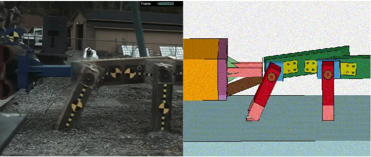
[image:3.595.110.487.240.400.2]Two tests were prepared to evaluate the design of end-terminal energy absorption. This test validated the numerical model and considers the pendulum impact test with 2000 kg mass. Graphical model of simulation and pendulum impact is shown in figure 2.1. The result of pendulum impact test and finite elements approach shows the design of terminal by steel-backed timber to be practicable. But conducting two tests consist of 820-kg car and 2000-kg pickup, required to validate the final design of terminal. In this case pendulum cannot simulate the impact of real vehicle on terminal. (Dhafer Marzougui, 2009).
Figure 2.1: Sequential images from simulation and real test with pendulum
Nauman M. Sheikh in 2006 evaluated the W6x8, 44inches, 36 inches, and 32 inches posts embedded in soil a pendulum impact test were used. This pendulum had a mass of 1850-lb and speed of 22mph when impacted to the guardrail. For comparing data, two tests were performed for each post, the result of experiment shows that the posts were not deformed for all tests. But, slight bending happened in one of the tests at ground for 44-inch embedment.
For evaluating the connection of base plate to post two pendulum impact tests were done by Akram Abu-Odeh in 2003 along with the strong and weak axis of the post. A crushable nose was installed in front of the mass and the calculated speed was 35km/h. as a result of this experiment for impact along strong axis the post break at the base plate and for weak axis, the post did not release at the base pate. Gabler in 2009 studied current damage on guardrails; they introduced 26 damages and recommends pendulum testing to better understanding of these damages.
3. TESTING GUARDRAILS USING BOGIE VEHICLE
Another useful surrogate device which could be used for both the high and low-speed tests is bogie vehicle. A kind of dynamic test was designed by Weijia.Wu in 2007 to force the applied longitudinal guardrail beam to the post in the lateral direction. JOHN D.REID, D. L in 1998 performed 10 bogie tests to evaluate the result of numerical model and all of them had the same design for deflector plate. Several parameters considered in tests which were included for the structure of deflector and also for the guide tube length. In this study design, the deflector plate was improved as a result of bogie test and simulation. Another study conducted (John D. Reid, J. R, 2002) in which, Bogie test was used to determine the bursting force to rail. Two kinds of thickness 3.2 and 4.8 mm were experimented by simulation and bogie test. These tests were in close proximity with each other.
For configuration and obtaining the force deflection of several post-to culvert attachments, bogie vehicle test was used. For all the seven tests, the speed and weight of bogie vehicle was 16.1 km/hr and 2,217 kg respectively. For the first and last 5 five tests, failure occurred between the post and base plate. On the other hand, for the seventh test there were no weld failure or bolt damage at the post and plate. The reason given was that the failure mechanism is more readily reproducible than the weld failure. (Karla A. Polivka, 2002).
For the pavement post guardrail the influence of mow strips had not been investigated (Nathaniel R. Seckinger A. A, 2005). For this case the posts were subjected to the impact by a bogie vehicle with weight of 839kg and speed of 35km/hr. pavement mow strip, guardrails was evaluated by both the simulation and real crash test and recommends suitable shape and diameter of post. Dynamic impact tests were numerically simulated and full-scale mow strip system models were assembled using the subcomponent models. With reference to nationally accepted criteria, crash tests of a strong post steel guardrail system and a wood post guardrail system encased in the selected mow strip configuration were considered to be successful. Recommendations for implementation are provided.
Three similar posts are subjected to the impact by a bogie test which had a mass of 1030 kg and speed of 18 km/hr (Weijia Wu, 2007), Based on the data of bogie vehicle and the quasi-static, dynamic resistance of bogie test was twice the quasi-static test. Graham et al, in 1967 developed a standard, at New York traffic barriers .they used both the real crash test and bogie vehicle to evaluate the performance of guardrails post in soils and rigid foundation. In another study Kuipers and Reid in 2003 studied the depth of embedment of steel post for median guardrails, A bogie vehicle used for the impact on the posts, the kind of post which was subjected to the force was W6x16 .The average forces which produced was about 29 KN and 29.6 KN for both the deflection was 381 and 597 mm respectively .For 940 mm embedment depth, the post was pulled out of the soil after impact. The maximum energy was absorbed during the rotation of the post in the soil; in this, the amount of energy absorbed was 24.9kj. For embedment, 1,016-mm the total energy absorption was calculated, 29.8 kJ and shows 16 % increase.
In another study dynamic test on post was performed by using 7.1kn impact of bogie vehicle with speed of 32km/h. for the first test and in the second test, for propelling bogie vehicle they used a pickup. The results of tests were used for determining the post diameter in the MGS (David E. Kretschmann, 2007). Ronald K. Faller in 2004 utilized bogie vehicle to evaluate the appropriate embedment depths for posts and also to draw the curve of force-deflection. The result shows 1.016mm embedment depth and was the best option for using in guardrails.
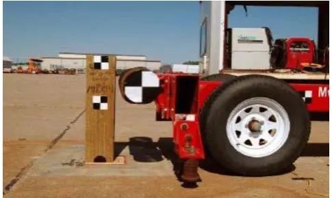
[image:5.595.170.413.276.421.2]Midwest Roadside Safety Facility (MwRSF) performed bogie vehicle dynamic test on a kind of wood post known as CRT in a rigid foundation. The figure 3.1 shows the bogie and the wood post which is subjected to the impact. Three kind of test were performed at 0 degree impact angle, 90 degrees impact angle along the weak axis and along the diagonal axis. Because of putting CRT in the rigid foundation the amount of energy dissipated was calculated and is considerably less than the post subjected to the impact by pendulum in the soil. (Akram Y. Abu-Odeh, 2010).
Figure 3.1: the bogie vehicle which used in experiment
As a summary for this section the bogie vehicle seems to be a useful method to simulate dynamic force to the guardrails, most of the researcher as mentioned in this paper used this device for evaluating the characteristic of the post, embedded in the soil. And in comparison with pendulum, this method has two main advantages: firstly it is easy to provide desirable speed of vehicle via this procedure. Secondly bogie vehicle could impact to the guardrail with any angle.
4. CONCLUSION
5. REFERENCES
Akram Abu-Odeh, R. P. (2003). Analysis and Design of the Texas T-6 Breakaway Bridge Railing System Using Finite Element Methodology, presented in TRB 2003 Annual Meeting Transportation Research Board, Washington
Akram Y. Abu odeh, K.M. K. (2010) Evaluation Of Existing T-Intersection Guardrail Systems For Equivalency With Nchrp Report 350 Tl-2 Test Conditions, TRANSPORTATION INSTITUTE PROVING GROUND, Texas
Brian A. Coon, J. D. (2006) Reconstruction techniques for energy-absorbing guardrail end terminals, Accident Analysis and Prevention, Vol.38, No.1, 1-13.
Brown, C. M. (1998). Pendulum testing Of an Frp Composite Guardrail Foil Test, report no. s96po19 Through96po23, U.S.Deportment of Transportation Federal Highway Administration, Georgetown McLean
David E. Kretschmann, R. F. (2007) Investigating the Use of Small-Diameter Softwood as Guardrail Posts: Static Test Results, U.S. Department of Agriculture – Forest Service, Madison, Wisconsin:
Dhafer Marzougui, C.D (. (2009) Development of a New End Treatment for Steel-Backed Timber Guardrail Phase I Conceptual Design. National Crash Analysis Center, Washington.
Diew, A. K. (2010) The Application of Empirical Bayes Approach for Identifying and Ranking Hazardous Junctions Case Study: Singapore Signalized Junctions, Journal of the Eastern Asia Society for Transportation Studies , Vol. 8, 2062-2077.
Douglas J. Gabauer, K. D. (2010) Pendulum testing as a means of assessing the crash performance of longitudinal barrier with minor damage, International Journal of Impact Engineering , Vol.37, No. 11, 1121-1137.
Gabler, D. J. (2009) Evaluation of Current Repair Criteria for Longitudinal Barrier with Crash Damage, Journal of Transportation Engineering, Vol. 135, No. 4, 225-234.
Graham, M.D., Burnett, W.C., Gibson, J.L., and Freer, R.H., New Highway Barriers: The Practical Application of Theoretical Design, Report No.174, 1967, Highway Research.
Jason A. Hascall, R. K. (2007) Investigating the Use of Small Diameter Softwood as Guardrail Posts (Dynamic Test Results) U.S. Department of Agriculture Forest Service, Madison, Wisconsin
JOHN D.REID, D. L. (1998) Design And Simulation Of Asequential Kinking Guardrail Terminal , International Journal of Impact Engineering, Vol. 21, No. 9, 761-772.
Karla A. Polivka, M. E. (2002) A Guardrail Connection for Low-Fill Culverts, presented at 82nd Annual Meeting Transportation Research board , Washington, D.C,2004
Kuipers, B.D and Reid, J.D (2003) Testing of W152X23.8 (W6X16) Steel Posts-Soil Embedment Depth Study for the Midwest Guardrail System, Report No. TRP-03136-03, Midwest Roadside Safety Facility, the University of Nebraska-Lincoln, Lincoln, Nebraska.
Lawrence C.Bank, J. Y. (1998) Pendulum Impact Test On Steel W-Beam Guardrails,
Journal Of Transportation Engineering , Vol. 124, No. 4 ,319-325.
Mitani, H. Y. (2005) Vehicle Behavioral Safety Assessment For Unsignalized Small Intersections To Evaluate Collision Avoidance System, Journal of the Eastern Asia Society for Transportation Studies , Vol. 6, 2667 - 2675.
Nathaniel R. Seckinger,Akram Abu-Odeh, Roger P. Bligh And Paul N.Roschke (2005), Performance of Guardrail Systems Encased in Pavement Mow Strips, Journal Of Transportation Engineering, Vol. 131, No. 11,851-860.
Nauman M. Sheikh, R. P.O. (2006) Developing Of An Energy Absorbing End terminal For Open Box Beam Guardrail, presented at 9th International LS-DYNA Users Conference , Dearborn, 2006
Nguyen Huu DUC, D. T. (2010) Comparative Study on Vietnam Traffic Safety:The Existence of a 5-Years Cycle in Road Traffic Accident Development, Journal of the Eastern Asia Society for Transportation Studies , Vol. 8, 1854-1864.
Paul N. Roschke, R. P. (1995) Commingled Plastic guardrail Post, Journal Of Transportation Engineering , Vol. 121, No. 2 ,201-213.
Pichai Taneerananon, O. S. (2005). Bus Crash Situation In Thailand : Case Studies, Journal of the Eastern Asia Society for Transportation Studies , Vol. 6, 3617 - 3628.
Ronald K. Faller, K. A. (2004) Midwest Guardrail System for Standard and Special Applications. Transportation Research Board, presented at 83rd Annual Meeting, Transportation Research Board, Washington, D.C.