International Journal of Emerging Technology and Advanced Engineering
Website: www.ijetae.com (ISSN 2250-2459,ISO 9001:2008 Certified Journal, Volume 3, Issue 10, October 2013)
202
FE Analysis of Positioning Slides of Micro Milling Machine
Sushant Thambkar
1, Bhagyesh Deshmukh
21,2Walchand Institute of Technology, Solapur, India.
Abstract— Micro milling is one of the essential machine tool in development of the micro systems. However use of such intricate and complex components increases the cost of machine. In retrofit approach, components are selected from salvage considering its sustainability in terms of topology, accuracy and repeatability to build a 3-axis Micro milling machine. However performance obtained from such system depends upon various parameters. The slides used in machines may be associated with undesired deflections due to cutting and operating forces thereby affecting the performance obtained. In order to estimate the deflections at static conditions, analytical solution is obtained and so as to validate the analytical results, simulation is carried out. This analysis is carried out on X-Y slide and it is observed that the deflections are well within the range and results of analytical solution and simulation are in very close agreement.
Keywords— Micro milling machine, deflection, analytical solution, FEA.
I. INTRODUCTION
Need of miniaturization has initiated the development of micro machine. Machining at a scale of micrometer has demanded the accuracy and high resolution that can be offered by machine tools. Accuracy of machined components developed using Micro milling machine is affected by machine bed, spindle system, drive systems and controller incorporated. Machine bed and spindle system are major elements influences the performance obtained from Micro mill. Vertical configuration of machine bed is preferred as it distributes the weight in straight line towards gravity and can offer greater stability. Intricate and complex components such as air bearing spindle system driven by DC brushless motor, Linear stages drive with aerostatic bearing and linear motor with direct drive technology system are important technological aspects of Micro mill. Typical machines involve precision slides, aerostatic bearing etc. which are costlier due to technology involved. A different concept of micro milling machine is developed by reuse of components The design of Micro milling machine using components selected from salvage has a work table of 19 X 19 X 25 mm with resolution of 0.1 µm. X-Y-Z slides to be used are of make PI. A controller along with these slides is used to control 3 axes of machine.
The slide being the critical component is to be tested for deflection/deformation in order to ascertain the performance. Analytical solution is obtained for the deflection and is validated using simulation.
II. LITERATURE
[image:1.612.382.486.571.699.2]Mechanical machining processes such as cutting, grinding, drilling, and polishing have been playing an important role in manufacturing work pieces and have allowed for more precision machining. Micro milling using end mills of diameters in the sub-millimeter range, a process of creating features measured in micrometers, is rapidly growing in advanced industries [1]. The micro milling process is a flexible process and is able to create more complex microstructures where the surface topography and cutting forces are dependent upon the cutting parameters. The cutting force is one of the most representative process variable which allows a judgement and explanation of basic phenomenon in machining processes. Examples are the wear behaviour, the calculation of the energy quotas in tool, chip and workpiece, the setting of optimized input variables or the predicting of the workpiece quality. Also for the design of machine tools the knowledge of static and dynamic cutting forces is of major importance [2]. The cutting forces that developed are very small as compared to conventional machining during micro machining. Cheng-Zhe Jin et al experimented characteristics of cutting forces in Micro milling machine. Figure 1 shows the relationship between the experimental feed direction and the normal direction cutting forces at the spindle speed of 120,000 rpm.
International Journal of Emerging Technology and Advanced Engineering
Website: www.ijetae.com (ISSN 2250-2459,ISO 9001:2008 Certified Journal, Volume 3, Issue 10, October 2013)
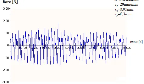
[image:2.612.339.547.168.266.2]203 It is observed that as the depth of cut increases cutting forces also increases. Figure indicates that depth of cut is varied from 0.5 to 2.5 µm/tooth then the forces that are developed are 2.5 N [1]. J.P. Wulfsberg et al [2] presented piezoelectric force measurement system for micro machining operations. This system measures forces developed during micro milling machining. In this Force progression in the Y-axis is checked for10ms during milling. Figure 2 shows a force progression during milling (spindle speed (n)=110.000 min-1; feed speed (vf)=20mm/min; width of cut (ae)=0,01mm; depth of cut (ap)=0,3mm).
Figure 2 Force progression in the y-axis for 10ms during milling [2]
Atul Dhanorker et al [3] experimented Micro end milling processes. In which graph is plotted between tool rotation angle and cutting force. In which feed and revolution (rpm) of tool are varied to check cutting forces. A maximum force developed is 3 N. For the analysis purpose Xinchun luo el al uses FEA (ANSYS software) for the analysis of Bench top Micro milling machine. [4]. Duhong huo et al uses FEA for performance analysis of bench top Micro milling machine. In which static analysis, modal analysis, harmonic response analysis is done for the frame of Micro milling machine [5]. FE analysis is best suited. Hence ANSYS software is used to check the deflection of positioning slides. From the literature it is observed that cutting forces are varies from 1 N to 5N and analysis is to be carried out for a range of force minimum up to 5N. FEA is implemented by various researchers and numerical simulation technique is useful for the simulation based analysis.
III. ANALYSIS BY ANALYTICAL SOLUTION
In tune with the objective of analysis (the maximum deflection), detailed analysis is carried out using the classical bending equations for the slide shown in Figure 3.
[image:2.612.56.285.285.420.2]This analysis is carried out for static structural analysis case as interest is to estimate the deflection.
Figure 3 Slide considered for analysis
In the deflection analysis of slide, as it is supported at one end, it is considered as a cantilever beam. A 2D equation is used since the force will be exerted at a very small zone being a case like a cantilever beam. The detailed steps are presented herewith.
Deflection of cantilever beam is given by following equation,
(1)
Where,
P= Cutting force exerted by tool (N) L= Length of beam (Base plate). E=Young‟s modulus
I=Moment of Inertia.
Moment of inertia for a rectangular cross-section beam is given by
(2)
Deflection of base plate (slide and base plate together) is obtained as follows,
L=138.25 mm,
I = 21970 mm4.
Using equation (4.1) deflection (∆l) is obtained as
International Journal of Emerging Technology and Advanced Engineering
Website: www.ijetae.com (ISSN 2250-2459,ISO 9001:2008 Certified Journal, Volume 3, Issue 10, October 2013)
204 Similar analysis is carried out over a range of force (1N to 10N) using MICROSOFT EXCEL and the details are given in the Table I. In order to validate the deflection obtained by analytical equation, a simulation using ANSYS workbench is undertaken and is discussed in detail in the section following.
TABLEI
RESULTING DEFORMATION BY ANALYTICAL
Force (N) Deflection (µm)
1 0.573
1.5 0.8595
2 1.146
2.5 1.4325
3 1.719
3.5 2.0055
4 2.292
5 2.5785
6 2.865
7 3.438
8 4.011
9 4.584
10 5.157
IV. ANALYSIS BY NUMERICAL SIMULATION
Numerical simulations are carried out using ANSYS and the procedure incorporated is mentioned in this section.
A. ANSYS Pre-processor
a. Creation of the model geometry
[image:3.612.66.272.229.379.2]To begin with the analysis process, the Model generation is carried out in this processor. A solid Model of the generated in CATIA is imported in ANSYS workbench as shown in Figure 4. Due care is required in aligning the axes defined.
Figure 4 CATIA model of base plate and positioning slide
b. Definite material properties
In the present work, Aluminium is used as material for design. The Young‟s modulus and Poisson‟s ratio for aluminium is taken as 0.70 x 10⁵ N/mm2, 0.35 respectively.
c. Generating the mesh
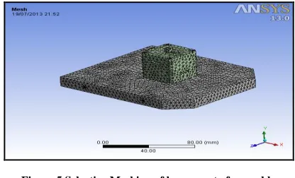
[image:3.612.336.544.258.384.2]As the material properties for the material selected are defined for the solid model of base plate and positioning slides of Micro milling machine, the mesh generation is carried out as the subsequent step. The model meshed using Solid element „Tet 10‟ (ANSYS element library) shown in Figure 5. Due care is required in meshing of a sensitive zone and comparatively insensitive zone. Sensitive zones are hence meshed using fine mesh whereas insensitive zone is meshed using relatively coarse mesh.
Figure 5 Selective Meshing of lower part of assembly
In this step, generated number of the nodes and elements are observed as 55737and 35010 respectively.
B. ANSYS solution Pre-processor
The meshed model is imposed with the boundary conditions and the load steps for the detailed displacement (deformation) and stress analysis.
a. Define analysis type and analysis option
In the current work, one of the prime objectives is to attain the micro displacements. Dynamic aspect is not considered as the scope of the study and hence in tune with the objectives and scope of the study, the „static structural analysis‟ module of ANSYS is considered for the analysing the positioning slides. The static analysis focused on aspects such as force and displacement relationships.
b.Specify boundary conditions
[image:3.612.67.269.524.635.2]International Journal of Emerging Technology and Advanced Engineering
Website: www.ijetae.com (ISSN 2250-2459,ISO 9001:2008 Certified Journal, Volume 3, Issue 10, October 2013)
[image:4.612.75.266.131.378.2]205 Figure 6 Fixed support
Figure 7 Force application
c. Obtain solution
This step initiates the solution process of model of positioning slides. The solution is carried out for resulting deformation. The compiler processes the model and keeps the solution ready for the further processing.
C. ANSYS General Postprocessor
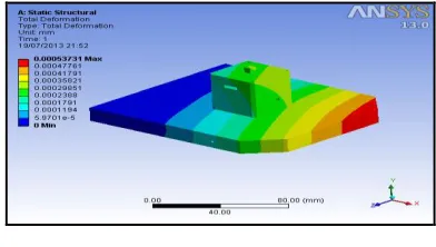
[image:4.612.69.265.510.621.2]The solution obtained by the solution process is a general solution. The Displacement plot is obtained for the particular load condition and is represented in Figure 8.
Figure 8 Simulated Total deformation result
A maximum deformation of 0.0005373mm (0.53 µm) is observed corresponding to a force of 1N. Figure 9 shows the von misses stresses developed.
Figure 9 Von misses stresses
V. RESULTS
The displacement analysis is carried out over a range of input force (1 N to 10 N) using ANSYS and the corresponding values are represented in Table II.
TABLEIII
RESULTING STRESS AND DEFORMATION BY SIMULATION
Force (N)
Total Deflection (µm)
Equivalent Stress (N/mm2 )
1 0.5373 0.1747
1.5 0.8059 0.26203
2 1.075 0.3494
2.5 1.343 0.43672
3 1.6119 0.52406
3.5 1.8806 0.61141
4 2.149 0.6988
4.5 2.418 0.7861
5 2.687 0.87344
6 3.22 1.0481
7 3.761 1.2228
8 4.299 1.3975
9 4.836 1.5722
10 5.373 1.7469
0 0.5 1 1.5 2 2.5 3 3.5 4 4.5 5 5.5 6
1 1.5 2 2.5 3 3.5 4 4.5 5 6 7 8 9 10
D
EF
LE
C
TI
O
N
(µ
m
)
FORCE (N)
FORCE V/S DEFLECTION CURVE
ANSYS
International Journal of Emerging Technology and Advanced Engineering
Website: www.ijetae.com (ISSN 2250-2459,ISO 9001:2008 Certified Journal, Volume 3, Issue 10, October 2013)
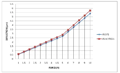
[image:5.612.66.272.254.379.2]206 The graph of force and the resulting deflection is illustrated in Figure 10. From this graph, it is observed the displacement curve for the forces are linear and deflection is maximum of 5.5 µm for force of 10 N. The results of deflection of base plate and positioning slide are compared with analytical calculations. It is observed that the both results are in very close agreement as shown in Figure 11. It indicates the correctness of the analytical model and the methodology adopted. The error obtained in estimation of the results is 6.18% which is acceptable.
Figure 11 Comparison of result of Analytical and ANSYS
VI. CONCLUSION
The design is found to be satisfactory since the results of the deflection analysis of positioning slides of Micro milling machine using analytical method are validated using the simulation.
The deflection is very negligible for the dimensions of the selected slides. The simulation has proved to be a vital tool in the analysis of a complex system like positioning system of a micro milling machine.
Acknowledgement
Authors are thankful to the management, Principal Dr. S.A.Halkude and Dr. K.H.Jatkar of Walchand Institute of Technology, Solapur for their continuous encouragement and support.
REFERENCES
[1] Cheng-Zhe Jin, Ik-Soo Kang, Jin-Hyo Park, Su-Hoon Jang and Jeong-Suk Kim. “The characteristics of cutting forces in the micro-milling of AISI D2 steel”, Journal of material science and technology, 2009.
[2] J.P. Wulfsberg, G. Brudek, „Detection of Cutting Forces in Micro Machining Operations‟.
[3] Atul Dhanorker and Tugrul Ozel, “An Experimental And Modeling Study On Meso/Micro End Milling Process”, ASME. 2006. [4] Xichun Luo, Kai Cheng, Dave Webb, Frank Wardle, “Design of
ultraprecision machine tools with applications to manufacture of miniature and micro components”, Journal of Materials Processing Technology, 2005.
![Figure 1 Relation between Feed/tooth v/s Cutting forces [1]](https://thumb-us.123doks.com/thumbv2/123dok_us/8724297.884999/1.612.382.486.571.699/figure-relation-feed-tooth-v-s-cutting-forces.webp)