Design and analysis of a bioinspired
modulebased robotic arm
Luo, Z, Shang, J, Wei, G and Renaut, L
http://dx.doi.org/10.5194/ms71552016
Title
Design and analysis of a bioinspired modulebased robotic arm
Authors
Luo, Z, Shang, J, Wei, G and Renaut, L
Type
Article
URL
This version is available at: http://usir.salford.ac.uk/id/eprint/39976/
Published Date
2016
USIR is a digital collection of the research output of the University of Salford. Where copyright
permits, full text material held in the repository is made freely available online and can be read,
downloaded and copied for noncommercial private study or research purposes. Please check the
manuscript for any further copyright restrictions.
Mech. Sci., 7, 155–166, 2016 www.mech-sci.net/7/155/2016/ doi:10.5194/ms-7-155-2016
© Author(s) 2016. CC Attribution 3.0 License.
Design and analysis of a bio-inspired module-based
robotic arm
Zirong Luo1, Jianzhong Shang1, Guowu Wei2, and Lei Ren3
1School of Mechatronics Engineering and Automation, National University of Defence Technology, 410073 Changsha, China
2School of Computing, Science and Engineering, University of Salford, Salford, M5 4WT, UK 3School of Mechanical, Aerospace and Civil Engineering, University of Manchester,
Manchester, M13 9PL, UK
Correspondence to:Zirong Luo ([email protected]), Guowu Wei ([email protected]) and Lei Ren ([email protected])
Received: 30 March 2016 – Revised: 4 July 2016 – Accepted: 11 July 2016 – Published: 12 August 2016
Abstract. This paper presents a novel bio-inspired modular robotic arm that is purely evolved and developed from a mechanical stem cell. Inspired by stem cell whilst different from the other robot “cell” or “molecule”, a fundamental mechanical stem cell is proposed leading to the development of mechanical cells, bones and a Sarrus-linkage-based muscle. Using the proposed bones and muscles, a bio-inspired modular-based five-degrees-of-freedom robotic arm is developed. Then, kinematics of the robotic arm is investigated which is associated with an optimization-method-based numerical iterative algorithm leading to the inverse kinematic solutions through solving the non-linear transcendental equations. Subsequently, numerical example of the proposed robotic arm is provided with simulations illustrating the workspace and inverse kinematics of the arm. Further, a prototype of the robotic arm is developed which is integrated with low-level control systems, and initial motion and ma-nipulation tests are implemented. The results indicate that this novel robotic arm functions appropriately and has the virtues of lower cost, larger workspace, and a simpler structure with more compact size.
1 Introduction
In the field of robotics, researchers and engineers have a dream of developing robotic arms with agile characteristics like the human arm to perform dynamic tasks under compli-cated and unconstructed environment. However, more than sixty years passed since the first robotic manipulator being patented by George G. Devol in 1954 (see Siciliano and Khatib, 2008), it is still too far to say that this dream has come true. Nevertheless, new ideas and concepts have been putting forward to explore the ways of developing more effi-cient, dexterous and feasible robotic arms.
In order to achieve desired flexibility, manipulability and reconfigurability, one of the efforts is devoted to the devel-opment of novel, high performance module-based robotic arms. These include, to mention but a few, the one degree of freedom T-type and I-type modules proposed by Guan et al. (2009); the three degrees of freedom tendon-integrated
hy-156 Z. Luo et al.: Design of a bio-inspired module-based robotic arm using sarrus linkage
brid robotic arm composed of a 2-DOF parallel mechanism and a 3-DOF serial kinematic chain. Jin and Gao (2002) stud-ied a new 6-SPS parallel manipulator with an orthogonal con-figuration. Wurst and Peting (2002) presented PKM concept for designing modular-based reconfigurable machine tools, and using slide module and swing module, Xi et al. (2006) proposed reconfigurable parallel robot consisting of two base tripods.
In addition, bio-inspired robotic arms have also been de-signed and developed. One of the earliest bio-inspired robot is a new robotic system coined DRRS (Dynamically Recon-figurable Robotic System) proposed by Fukufda and Naka-gawa (1988). This robotic system consists of a number of intelligent cells each of which has a fundamental mechan-ical function. Each cell can detach or connect itself to the other cells autonomously depending on a specified task, the robot can then be of a manipulator or a mobile robot, the system also has the function of self-repair. In 1990, Fukuda and Kawauchi (1990) further proposed a new kind of robotic system called CEBOT (The Cellular Robotic System), which is a distributed robotic system consisting of reconfigurable autonomous units called “cell”s, the robot can reconfigure itself to an optimal structure depending on the specified pur-pose and environment. Further, Kotay and Rus (1999) pro-posed a robotic module called “Molecule” to build self-reconfiguring robots, the Molecules support multiple modal-ities of locomotion and manipulation. In the same period, Rus and Vona (1999) discussed a robotic system composed of crystalline modules that can aggregate together to form distributed robot systems. The crystalline modules can also move relative to each other by expanding and contracting. This actuation mechanism permits automated shape meta-morphosis and provides a crystalline robot system the ca-pability of self-reconfiguration. More recently, Yim et al. (2000) presented a modular reconfigurable robot called Poly-Bot. PolyBot is a modular reconfigurable robot system com-posed of two types of modules serving as segments and nodes. A segment module has one degree of freedom and two connection ports, and a node module is rigid with no mobility and has six connection ports. It was reported that two PolyBot systems have been built, and a robot with up to 32 modules being bolted together have been tested.
In this paper, we propose a stem-cell-inspired mechanical robotic arm. Different from the robotic arms discussed above that each of their mechanical cells or molecules is not sepa-rated but a completed robotic module being integsepa-rated with control and software system, the mechanical stem cell pro-posed in this paper, inspired by the character of stem cell, at a more basic and fundamental level, is a type of pure me-chanical unit. This unit can be used to build different robotic modules in according to the practical applications.
Using the unit, a bio-inspired mechanical muscle based on Sarrus linkage is proposed, leading to the development of a 5-DOF bio-inspired robotic arm. This novel design helps aug-ment workspace and overcome some shortcomings of
con-ventional serial robotic arms. According to the available lit-erature, although Sarrus linkage (Lee, 1996) has many appli-cations in the field of robotics, including the crawling robot by Ranjana et al. (2006), the road vehicle by Gavin and Luis (2010) and the micro six-legged segmented robot by Katie and Robert (2011), there is no report on robotic arm that is constructed with Sarrus-linkage-based structures.
In this paper, a robotic arm evolved from a fundamental mechanical stem cell is for the first proposed, and its associ-ated kinematics, simulation, prototype and initial test results are presented.
2 Bio-inspired robotic modules
2.1 Bio-inspired mechanical cells
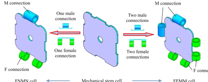
Stem cells have the remarkable potential to be developed into different cell types during their life cycles, and under cer-tain physiological or experimental conditions, they can be in-duced to become tissue- or organ-specific cells with special functions. Inspired by the evolution of stem cell, this paper proposes the concept of mechanical stem cells that are imma-ture and have the potentiality to evolve into various robotic modules, such as bone, joint and muscle etc. A typical exam-ple of such a concept is illustrated in Fig. 1 where a mechani-cal stem cell is designed as a solid plate without any connec-tions, in this sense, the cell is immature and its structure and function are indeterminate. However, with further evolution, the stem cell can grow connections at its edges and develop itself into mature mechanical cells. The connections can be of different types and two of them are considered in this pa-per, they are namely the male connection denoted as M and the female connection denoted as F. With the connections, mechanical cells such as FNMN cell and FFMM cell can be developed as shown in Fig. 1, where N standing for no con-nection. In Fig. 1, the FNMN cell consists of one mechanical stem cell and two connections, i.e. one female connection and one male connection; the FFMM cell has four connec-tions which are arranged as F, F, M and M in clockwise se-quence.
2.2 Development of mechanical bones
The FNMN and FFMM mechanical cells can further evolve themselves into mechanical bones forming structure modules that can be used as links or rigid bodies for constructing bio-inspired robotic arms. For example, the FNMN and FFMM mechanical cells can interact and grow into different mechan-ical bones such as the cubic bone, cuboid bone and polyhe-dral bone that are indicated in Fig. 2.
Z. Luo et al.: Design of a bio-inspired module-based robotic arm using sarrus linkage 157
3 2. Bio-inspired Robotic Module
2.1 Bio-inspired mechanical cell
Stem cells have the remarkable potential to be developed into different cell types during their life cycles, and under certain physiologic or experimental conditions, they can be induced to become tissue- or organ-specific cells with special functions. Inspired by the evolution of stem cell, this paper proposes the concept of mechanical stem cells that are immature and have the potentiality to evolve into various robotic modules, such as bone, joint and muscle etc. A typical example of such concept is illustrated in Fig. 1 where a mechanical stem cell is designed as a solid plate without any connections, in this sense, the cell is immature and its structure and function are indeterminate. However, with further evolution, the stem cell can grow connections at its edges and develop into mature mechanical cells. The connections can be of diverse types and two of them are considered in this paper, they are namely the male connection denoted as ‘F’ and the female connection denoted as ‘M’. With the connections, mechanical cells such as ‘FNMN’ cell and ‘FFMM’ cell can be developed as shown in Fig. 1 with ‘N’ standing for no connection. Hence, the FNMN cell consists of one mechanical stem cell and two connections, i.e. one female connection and one male connection. While, the FFMM cell has four connections which are arranged as F, F, M and M in clockwise sequence.
Fig. 1 Bio-inspired robotic cell
2.2 Bio-inspired bones
Further, the Using these two kinds of robot cells, we can build structure modules for the development of a robot arm. Figure 2 presents three kinds of robotic bones based on FNMN and FFMM cells.
(a) cubic bone (b)cuboid bone (c) polyhedral bone M connection
F connection F connection
M connection
Mechanical stem cell One female
connection
Two male connections
Two female connections
FMFM FMFM FNMN FMFM
One male connection
[image:4.612.125.464.67.200.2]FNMN cell FFMM cell
Figure 1.Bio-inspired mechanical cell.
(a) Cubic bone
(b) Cuboid bone
(c) Polyhedral bone
Figure 2.Bio-inspired mechanical bones.
to extend the cuboid bones. Figure 2c shows a polyhedral bone consists of eight FFMM cells and twelve FNMN cells. Compared to the cuboid bone, a polyhedral bone has more inner space which can be used to install and store actuators, sensors and other member modules.
A bio-inspired mechanical bone developed through the mechanical cells have three advantages. First, its structure is simple, modular and apt-to-be fabricated. Second, its struc-ture is reconfigurable and flexible. Third, the inner hollow space of these mechanical bones can be used to
accommo-date sub modules of robot, which is very useful for some special applications such as space technology.
2.3 Bio-inspired Sarrus-linkage-based mechanical muscle
Sarrus linkage (Sarrus, 1853) is a one degree of freedom spatial linkage that was invented by Pierre Frédéric Sarrus (1798–1861) in 1853, that can transfer rotary motion into lin-ear motion, or inversely transfer the linlin-ear motion into stan-dard rotary motion (Chen et al., 2013); sometimes it is also referred to as spatial crank mechanism. It provides a great va-riety of possible motions and may accomplish complex tasks beyond what planar linkages are capable of as indicated in He et al. (2014) and Li et al. (2013). The classic Sarrus link-age is a two-limb six-bar linklink-age of which each limb contains three parallel revolute joints, with the first joint of both limbs lying on the base plane and the third joint of both limbs lying on the platform plane.
Based on the Sarrus linkage, we can artificially nurture the FNMN and FFMM mechanical cells into a bio-inspired me-chanical muscle that is composited of six meme-chanical cells connected by six revolute joints as indicated in Fig. 3a. Like the Sarrus linkage, the mechanical cells are jointed to form two sets of limbs, each of which being a four-link chain. The first chain is comprised of two FFMM cells as the bottom end labelled 1 and the top end labelled 4, and two FNMN cells serving as side links 2 and 3; the cells are connected by three parallel joints whose axes are denoted as A, B and C as indicated in Fig. 3a. Similarly, the other branch is com-posed of two FFMM cells serving as bottom end 1 and top end 4 which are of duplicates of the first branch, and two FNMN cells acting as side links 5 and 6; the links are joined by three parallel revolute joints whose axes are D, E and F, respectively.
[image:4.612.53.279.240.559.2]158 Z. Luo et al.: Design of a bio-inspired module-based robotic arm using sarrus linkage
(a) Standard sarrus structure (b) Sarrus structure with redundant chains
a
a θ
φ
O1
O4
6 5 4 3
2
1
F
E
D C
B
A
[image:5.612.312.546.64.341.2]θ
Figure 3.Bio-inspired Sarrus-linkage-based mechanical muscle.
does not alter the motion performance and output character-istics of a standard Sarrus structure but provides a more sta-ble and reliasta-ble structure which is capasta-ble of carrying more payload. As illustrated in Fig. 3b, assuming that the bottom cell is fixed, the top cell can only has translational motion with respect to the bottom cell. The lower-side cells rotates about the bottom cell, and the upper-side cells rotate respec-tively about their adjacent lower-side cells and translate with the top cell. Obviously, the linear motion of the two paral-lel ends leads to the circular motion of the joints; and on the other hand, the circular motion of the joints results in the linear motion between the two parallel ends. Hence, this me-chanical muscle can not only be used as a translational joint, but also acts as a supporting structure to expand further the workspace of a robotic arm.
Further, given the structure parameters of the Sarrus struc-ture as illustrated in Fig. 3a, there exist ϕ+2θ=2π and dO1O4=a
√
2−2 cosϕ with dO1O4 standing for the dis-tance between pointsO1andO4.
3 Design and kinematics of the bio-inspired robotic arm
3.1 Design of a bio-inspired modular 5-DOF robotic arm
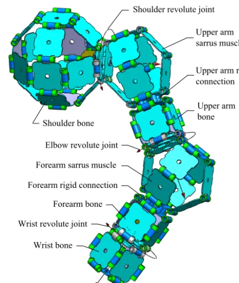
Based on the mechanical bones and muscle developed from the mechanical stem cells in the previous section, differ-ent type of robotic arms can be evolved and grown satisfy-ing specific purpose and environment, and one bio-inspired modular-based 5-DOF robotic arm is developed in this pa-per as illustrated in Fig. 4. This bio-inspired robotic arm is composed of three bio-inspired bones, i.e. the shoulder bone, upper-arm bone and forearm bone, and two bio-inspired mus-cles as the upper-arm muscle and the forearm muscle, con-nected by three revolute joints, that is, the shoulder joint, the elbow joint and the wrist joint, and two rigid connections as the upper arm rigid connection and the forearm rigid connec-tion. It can be seen that the robotic arm is purely developed from the mechanical stem cell presented in Sect. 2.1. Re-garding the degrees of freedom of the robotic arm, there are three revolute joints, two 1-DOF Sarrus-linkage-based
mus-
Shoulder bone
Shoulder revolute joint
Upper arm sarrus muscle
Upper arm rigid connection
Upper arm bone
Elbow revolute joint
Forearm sarrus muscle
Forearm rigid connection
Forearm bone
Wrist revolute joint
[image:5.612.52.283.67.176.2]Wrist bone
Figure 4.A bio-inspired modular 5-DOF robotic arm.
cles and two rigid connections, hence the total degrees-of-freedom of the proposed robotic arm is five.
For this robotic arm, through the shoulder revolute joint, it can realize an circular 360◦rotation of upper arm; through the upper arm Sarrus-linkage-based muscle, it can realize a combined rotation and translation of the upper arm and be-low parts, and change the workspace of the arm; through the elbow revolute joint, it can realize an entire 360◦rotation of forearm and the parts below; through forearm Sarrus muscle, it can realize a combined rotational and translational motion of the forearm and parts below, and change its workspace; further, through the wrist revolute joint, it can realize circu-lar 360◦rotation of the wrist bone.
As described above, the dexterous motion generated by the proposed robotic arm provides augmented workspace. Re-garding its application, the shoulder can be fixed on the base or combined with the other robots, we can also directly con-nect the upper Sarrus arm to the base or the other robots with the shoulder revolute joint. By accurate controlling the mo-tion of each joint, the robotic arm can execute specific mis-sion satisfying various customer requirements.
3.2 Forward kinematics
Z. Luo et al.: Design of a bio-inspired module-based robotic arm using sarrus linkage 159
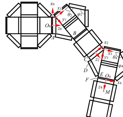
conventional ones and is investigated in this section. In or-der to describe the position and orientation of the proposed robotic arm, a global coordinate system{O0−x0y0z0}is lo-cated at the shoulder joint, and four body-attached coordi-nate systems are established at the upper arm muscle, upper arm born, forearm muscle and forearm born, respectively, as shown in Fig. 5. As the robotic arm includes both serial and parallel kinematic chains, the traditional D–H method can-not be directly used to analyse its kinematics. In this paper, a more general approach, that is, homogeneous coordinate transformation method is used. By firstly solving the trans-formation matrices between the coordinate systems, and con-sequently deriving the total transformation matrix, we can obtain a matrix representing the posture of the wrist bone with respect to the global coordinate system leading to the investigation of the workspace and inverse kinematics of the proposed robotic arm.
Considering the motion sequence of the robotic arm, it involves both translational and rotational transformation. Herein, the homogeneous transformation matrix for trans-lation is denoted as Trans(a, b, c) with a, b andc being the coordinates of a displacement vectorai+bj+ck, and the homogeneous transformation matrices for rotations about thex,y andzaxes are denoted as Rot(x,θ), Rot(y,θ) and Rot(z,θ), respectively, as defined in Cai (2009). Further, for conciseness sake, the sine and cosine functions are denoted assandc, respectively.
As discussed above, the bio-inspired robotic arm is built by the FFMM and FNMN mechanical cells evolved from the mechanical stem cell, thus all the unit modules used to con-struct the robotic arm have the same con-structure parameters and we assume that lengths of the side and thickness of a unit module are respectivelya andb. According to the kinemat-ics of Sarrus linkage, the anglesθi andϕi (i=2 and 4) in the two Sarrus-linkage-based muscles in the robotic arm have the following relationship
2θi+ϕi =2π (i=2 and 4). (1)
Referring to Fig. 5, the position vector of the centroid point M in the wrist bone can be expressed in reference frame
{O4−x4y4z4}in homogeneous coordinate form as
4p= [0 0a/2+b1]T. (2)
Coordinate system {O4−x4y4z4} is transformed from frame {O3−x3y3z3} by a rotation about the y3 axis by an angle θ5 followed by another rotation about the x4 axis by −π/2, and subsequently a translation q34 along the z4 axis. With respect to reference frame {O3}, the transla-tionq34can be expressed as
3p
34=O3O4=O3D+DE+EF+F O4
=a/2 2asinθ4+b0 1T, (3)
[image:6.612.309.545.67.291.2]O0 C O4 y1 x0 z0 z4 θ2 x1 φ2 φ4 θ4 x3 z2 x2 x4 y3 B A M D E F
Figure 5.Geometry and coordinate systems of the robotic arm.
such that the homogeneous transformation matrix that de-fines reference frame{O4}relative to reference frame{O3} can be given as
T34=Trans
3p 34
Rot (y3, θ5) Rot (x4,−π/2)
=
cθ5 −sθ5 0 a/2 0 0 1 2asθ4+b
−sθ5 −cθ5 0 0
0 0 0 1
. (4)
Similarly, according to Fig. 5, posture of coordinate sys-tem{O3}can be obtained from reference frame {O2}by a rotation about thez2 axis by angleθ3 with a following ro-tation about the x2 axis by π/2 and a translation given by vectorq23. The translational vectorq23 can be presented in reference frame{O2}as
2p
23= [a/2b0 1]T, (5)
and therefore transformation matrix that defines frame{O3} with respect to frame{O2}can be obtained as
T23=Trans
2p 23
Rot (z2, θ3) Rot (y2, θ4−π) Rot (x2, π/2)
=
−cθ3cθ4 −cθ3sθ4 sθ3 a/2
−sθ3cθ4 −sθ3sθ4 −cθ3 0 sθ4 −cθ4 0 b
0 0 0 1
160 Z. Luo et al.: Design of a bio-inspired module-based robotic arm using sarrus linkage
Further, by defining the displacement vector of the origin of frameO2with respect to the origin of frame{O1}as 1p
12=O1O2=O1A+AB+BC+CO2
=a/2a(1+2 sinθ2)+3b0 1T. (7) Transformation of coordinate system {O2}with respect to reference frame{O1}that is achieved by a rotation about the x1 axis by−π/2 and a translation with displacement vec-tor1p12can be expressed as
T12=Trans
1p 12
Rot (x1,−π/2)
=
1 0 0 a/2 0 0 1 a(1+2sθ2)+3b 0 −1 0 0
0 0 0 1
. (8)
From Fig. 5, the displacement of the origin of reference frame{O1}with respect to the origin of frame{O0}can be given as
0p
01= [a/2b0 1]T, (9)
thus, the transformation from frame {O1} to frame {O0} which is performed by a rotation about the z0 axis by an-gleθ1, a following rotation about thex0axis byπ/2, and a subsequent translationp01can be derived as
T01=Trans
0p 01
Rot (z0, θ1) Rot (y0, θ2−π) Rot (x0, π/2)
=
−cθ1cθ2 −cθ1sθ2 sθ1 a/2
−sθ1cθ2 −sθ1sθ2 −cθ1 0 sθ2 −cθ2 0 b
0 0 0 1
. (10)
Finally, multiplying all the four transformation matrices in Eqs. (4), (6), (8) and (10), we can have the final coordinate transformation matrix relating frame{O4}to frame{O0}as
T04=T01T12T23T34. (11)
Furthermore, combining Eq. (2) and Eq. (11), the posi-tion vector of pointMrelative to be base coordination sys-tem{O0}can be expressed as
0p=T
044p. (12)
According to Eqs. (2) and (12), it can be found that the wrist revolute joint has no effect on the position of the wrist bone centroidM, but it affects the orientation of wrist bone.
3.3 Inverse kinematics
Inverse kinematics provides background for position control of a robotic arm. Given the Cartesian coordinate of the end-effector in the transformation matrixT04, we attempt to de-rive the joint space formed by the five variablesϑ= {θ1,θ2,
θ3,θ4, θ5}. Since the proposed robotic arm is formed in a hybrid configuration, the inverse kinematics is highly non-linear such that it is difficult to find closed-form solutions. Thus, in this section, a numerical approach is proposed for solving the inverse kinematics of this bio-inspired robotic arm.
Dividing matrixT04into blocks, it has
T04=
R04 q04
0 1
, (13)
where, R04=[x04y04z04]T is the rotation matrix lying inSO(3) defining orientation of the wrist bone with respect to the base frame, andq04=[qxqyqz]T is a vector inR3 that locates the position of the centroidMof the wrist bone relative to the base frame.
Assuming that elements of the matrix in Eq. (13) are speci-fied, equalizing Eqs. (11) and (13) leads to a set of non-linear equations containing 5 variables and 12 equations which are not all independent. In this way, the inverse kinematic prob-lem of the proposed robotic arm is converted into finding so-lutions for the 12 dependent equations.
However, as aforementioned, due to the hybrid structure of the proposed bio-inspired robotic arm, there is no analyt-ical solution for the set of non-linear transcendental equa-tions, there exist only numerical solutions or approximate so-lutions. Further, unless in the case of special circumstances, there is no general direct method to get the numerical so-lution structure of non-linear equations, including the exis-tence of solution and multiple solutions. At present, there are two approaches for obtaining the numerical solution, i.e. the indirect method based on fixed point theorem, and the opti-mization method based on variational principle, both of these methods are based on iterative numerical solution adopt-ing the strategy of the “time for accuracy” termed in Zhou et al. (2008). Considering that the kinematics equations to be solved herein is a hyper-redundant non-linear transcendental one without direct solution available, we convert this prob-lem into a global optimization probprob-lem based on optimiza-tion methods as follows.
Given elements to matrixT04in Eq. (13) and equalizing it with Eq. (11), a set of dependent equation can be formed in terms of the five variables as
f1(θ1, θ2, θ3, θ4, θ5)=0 f2(θ1, θ2, θ3, θ4, θ5)=0
· · ·
f12(θ1, θ2, θ3, θ4, θ5)=0
, (14)
where the joint spaceϑ= {θ1,θ2,θ3,θ4,θ5}contains the five variables whose variation ranges are defined as
Z. Luo et al.: Design of a bio-inspired module-based robotic arm using sarrus linkage 161
In order to convert the equation solving problem into an equivalent optimization problem, Eq. (14) is converted to construct an energy function as
P(ϑ)=
12 X
i=1
|fi(θ1, θ2, θ3, θ4, θ5)|. (16)
Thus, the problem of solving non-linear transcendental equations is transformed into the problem of solving the en-ergy function complying with a given constraint. That is, given a sufficiently small positive number ε, the aim is to search for a set of values ϑ∗(θ1, θ2, θ3, θ4, θ5) such that P(ϑ∗)< ε holds, and as a result,ϑ∗(θ1,θ2,θ3,θ4,θ5) pro-vides as a set of approximate solutions for the above non-linear transcendental equations.
The numerical solutions of non-linear transcendental equations can be implemented in three steps as presented in Lu et al. (2008):
1. the existence of solutions: checking whether the equa-tions have soluequa-tions;
2. solution isolation: dividing the solution interval into smaller sub-intervals, for each sub-interval, there may exist a solution or not, and if so, we can refer to any point in the sub-intervals as an approximation solution;
3. solution precise: efforts to improve the accuracy of the approximation solution, make it satisfy a certain accu-racy requirement.
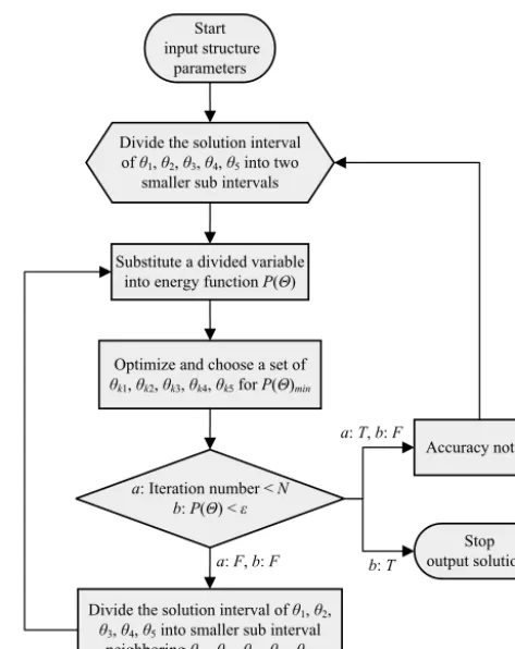
Considering the approach of solving non-linear equations based on global optimization method, a numerical iterative algorithm is proposed with its procedures shown in Fig. 6 and the specific process is interpreted as follows.
Firstly, define the maximum number of iteration N and the threshold errorε: if the calculation accuracy reaches the threshold errorε, stop the operation and the corresponding set of variable obtained may provide a set of inverse kine-matic solutions; if the number of operations has reached the maximum number of iteration N, even if accuracy error is larger than the threshold, also stop operations. Obviously, if the number of operations has reached the maximum number of iteration, and the calculation error is still big, this means that the accuracy of the solutions is not high enough to meet the threshold, we need to increase the maximum number of iterationNso as to achieve a set of more precise solutions.
Secondly, allocate values of the five variables θ1,θ2,θ3, θ4 andθ5according to their individual intervals defined in Eq. (15), and substitute them into the energy functionP(ϑ), then perform the iterative operation and select the minimum value of the energy function P(ϑ) searching for the opti-mized set of variable values (θk1, θk2, θk3, θk4, θk5) that leads to minimum value of the energy function denoted asP(ϑ)min.
Thirdly, continue allocating the five variablesθ1,θ2,θ3,θ4 andθ5in a smaller interval near (θk1,θk2,θk3,θk4,θk5), and
Substitute a divided variable into energy function P(Θ)
Optimize and choose a set of θk1, θk2, θk3, θk4, θk5 for P(Θ)min
Divide the solution interval of θ1, θ2,
θ3, θ4, θ5 into smaller sub interval
neighboring θk1, θk2, θk3, θk4, θk5 a: Iteration number < N
b: P(Θ) < ε
a: T, b: F
b: T a: F, b: F
Divide the solution interval of θ1, θ2, θ3, θ4, θ5 into two
smaller sub intervals
Stop output solutions Accuracy not fit Start
[image:8.612.309.546.64.362.2]input structure parameters
Figure 6.Flow chart for numerical solution of the proposed inverse kinematics.
running iterative operations. This will result in better mini-mum energy function valueP(ϑ∗) and the refined solutions for the five variables.
Repeat the above steps until the value of energy function is less than the threshold error or the iteration times reached the maximum number, the final output of the five variablesθ1,θ2, θ3,θ4andθ5will be a set of optimal solutions for the non-linear equations, that is, the inverse kinematic solution of the proposed robotic arm.
162 Z. Luo et al.: Design of a bio-inspired module-based robotic arm using sarrus linkage
Figure 7.Workspace of the bio-inspired robotic arm.
4 Numerical simulation and prototype of the robotic arm
4.1 Workspace and the typical configurations
[image:9.612.309.467.68.345.2]Based on the transformation matrix of the wrist bone cen-troid M given in Eq. (12), using Matlab package, we can plot the trajectory of pointMrelative to the fixed reference frame {O0}, that is, workspace of the wrist bone centroid M relative to the universal coordinate system, as shown in Fig. 7. In this example, the size of each stem mechanical cell isa×a×b=30 mm×30 mm×6 mm, in addition, the geo-metric collisions among member modules during spatial mo-tion are not considered.
Figure 7a and b show that the projection of the workspace of the robotic arm in any plane that is perpendicular to the zaxis is symmetric, the arm can make a whole circular mo-tion around the zaxis without any interference. Figure 7b and c show that the wrist can perform both forward and back-ward motions in a certain range in the negative direction of thezaxis, which provides potential capability of mimicking the motion of a human arm.
The workspace of the robotic arm in Fig. 7 also demon-strates that, without considering the size of the shoulder, when all the Sarrus-linkage-base muscles are fully retracted, the entire arm length in thezaxis direction is 108 mm, while the wrist centroidM can reach in a the range from−71 to 200 mm along zaxis, as illustrated in Fig. 7c and d.
Like-wise, when retracted, the position of wrist centroidMin the x- andy-direction can be zero, and the actual workspace is in the range from−175 to 175 mm along thex axis and the yaxis, respectively.
In addition, Fig. 8 demonstrates the typical configurations and workspace augmentation principle of the proposed robotic arm. Figure 8a shows one extreme phase of the robotic arm with two Sarrus-linkage-based muscles being fully retracted, compared with the fully expanded phase indicated in Fig. 8b and the intermediate phase in Fig. 8c, the robotic arm has the smallest volume of workspace at this phase, and in this configuration, the lengths of three equivalent links l1, l2 and l3 are l1=
p
a2+(a+4b)2, l2=
√
a2+4b2 and l
3=a/2+b, respectively; where, aandbare respectively the side length and thickness of the mechanical stem cells. Figure 8b shows another extreme phase of the robotic arm with the two Sarrus-linkage-based muscles being fully expanded, compared with Fig. 8(a), it can be found that the lengths betweenO0 andO2, and be-tweenO2andO4increase, such that the lengths of the three equivalent links becomel1=
p
(a/2+b)2+(5a/2+3b)2, l2=
p
(a/2+b)2+(3a/2+b)2 and l
3=a/2+b. Fig-ure 8c shows an intermediate phase in which configu-ration the lengths of the three equivalent links are l1= p
(a/2(1−cα)+bsα)2+(a(1+3sα/2)+b(3−cα))2, l2=
p
Z. Luo et al.: Design of a bio-inspired module-based robotic arm using sarrus linkage 163
(a) Fully retracted configuration
(b) Fully expanded configuration
[image:10.612.331.526.62.450.2]
(c) Intermediate phase
Figure 8.Geometric configurations of the bio-inspired robotic arm.
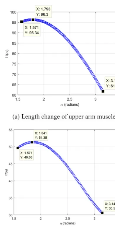
Based on the changes of the lengths of the three equivalent links l1,l2 andl3, the workspace augmentation function of the two Sarrus-linkage-based muscles can be formulated and illustrated in Fig. 9.
Figure 9a shows the relationship between length of the equivalent link l1 and the configuration angle αof the up-per arm Sarrus-linkage-based muscle. It can be found that as the upper arm muscle transform from the fully retracted
Figure 9. Workspace augmentation function of the two Sarrus-linkage-based muscles.
phase to the fully expanded phase, the actual length of linkl1 increases from 61.77 to 95.34 mm with the maximum length of 96.33 mm; which provides an extra 34 mm flexible length to the upper arm to achieve a linear motion along thezaxis.
Similarly, as shown in Fig. 9b, as the forearm Sarrus-linkage-based muscle transforms from the fully retracted phase to the fully expanded phase, the actual length of the equivalent linkl2increase from 30.59 to 49.66 mm, and the maximum length is 51.35 mm, which implies that an extra 20 mm flexible length is provided to the forearm for the lin-ear motion along thez4axis.
[image:10.612.333.526.69.235.2]164 Z. Luo et al.: Design of a bio-inspired module-based robotic arm using sarrus linkage
as a device carried by mobile robot to perform investigation, detection, rescue, transportation and other tasks.
4.2 Numerical solution for the inverse kinematics
Further, in order to validate the feasibility and accuracy of the proposed algorithm for inverse kinematic analysis, one numerical example is provided in this section. The valida-tion method and process is: first, give an initial value for the five variablesθ1,θ2,θ3,θ4andθ5, the two structure pa-rameters a andb of the mechanical stem cell, and substi-tute them into the forward kinematics matrix in Eq. (11) to achieve the transformation matrix; second, by equating the specified transformation matrix to Eq. (13), construct a set of non-linear transcendental equations containing 12 equations; third, by using the algorithm presented in Sect. 3.3, solve the equations and check the group of optimal solutions and minimum energy function value, this leads to the appropriate inverse kinematic solutions of the robotic arm.
Here, we assume that the mechanical stem cell has struc-ture parameters a=30 mm, b=6 mm, and a set of values within the ranges of the five joint variables is given as
ϑ=(θ1, θ2, θ3, θ4, θ5)=(π/1.5, π/1.2,−π/2,−π/6, π/3). (17) Firstly, substituting the variables in Eq. (17) into the trans-formation matrix in Eq. (11), the transtrans-formation matrix for representing the wrist bone coordinate system with respect to the global coordination system can be specified as
T04=
0.6250 0.3460 −0.6998 −43.3841
−0.6495 −0.2667 −0.7120 −96.1147
−0.4330 0.8995 0.0580 100.5428
0 0 0 1
. (18)
Then, by equating matrices Eqs. (18) and (13), a set of non-linear transcendental equation containing 5 variables and 12 equations can be constructed.
Subsequently, substituting the above matrix into the algo-rithm developed in Matlab™ program, and setting subdivi-sion number as n=48, the threshold error ε=0.5 and the maximum number of iterationsN=20, we get a set of in-verse kinematic solutions as
ϑ=(θk1, θk2, θk3, θk4, θk5)
=(2.0982,2.6129,−1.6797,−0.3984,1.0433), (19)
where, the number of iterations is 16, the minimum energy function valueP(ϑ)min=0.2250, such thatP(ϑ)min< εand therefore the operation terminates.
Finally, by substituting the results in Eq. (19) into the transformation matrix in Eq. (11), we can get a optimized numerical transformation matrix as
T004=
0.6645 0.3459 −0.6624 −43.3883
−0.6073 −0.2667 −0.7484 −96.1120
−0.4356 0.8996 0.0328 100.5100
0 0 0 1
[image:11.612.327.528.80.326.2]. (20)
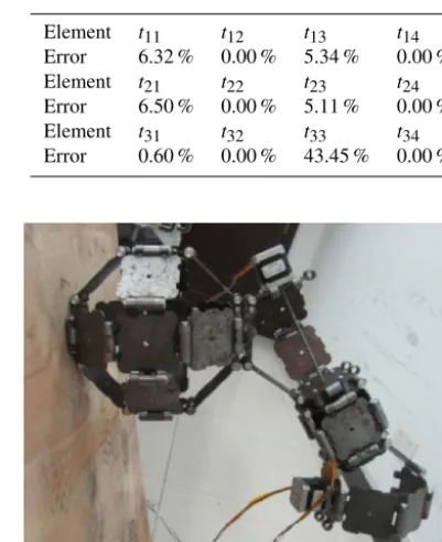
Table 1.Errors of the inverse kinematic solutions.
Element t11 t12 t13 t14
Error 6.32 % 0.00 % 5.34 % 0.00 %
Element t21 t22 t23 t24
Error 6.50 % 0.00 % 5.11 % 0.00 %
Element t31 t32 t33 t34
Error 0.60 % 0.00 % 43.45 % 0.00 %
Figure 10.Prototype of the proposed bio-inspired robotic arm.
Comparing the results in Eq. (20) with the specified val-ues in Eq. (18) as show in Table 1, it can be found that ex-cept for the elementt33, the errors are within the tolerance ranges, and the minimum value of energy functionP(ϑ) is within the acceptable range. Therefore, Eq. (20) can be ac-cepted as a set of inverse kinematic solutions for the robotic arm. At the same time, the results show that the numerical iteration method developed for the non-linear transcendental equations of robotic arm is valid and feasible.
4.3 Prototype and validation
Based on the forward and inverse kinematic analysis of the bio-inspired robotic arm, the mechanical cells were de-signed and fabricated, and a prototype of the proposed 5-DOF robotic arm was constructed, assembled and integrated with low-lever control system as illustrated in Fig. 10. It can be seen that, the mechanical system was completely built by using only the FFMM and FNMN cells that are developed from the mechanical stem cell, the three revolute joints at the shoulder, elbow and wrist are driven by rotary stepper motors, and the Sarrus-linkage-based muscles are driven by linear motors.
[image:11.612.46.288.414.456.2]Z. Luo et al.: Design of a bio-inspired module-based robotic arm using sarrus linkage 165
(a) Initial configuration of the robot
(b) Robotic arm shrinking
(c) Robotic arm swinging
(d) Robotic arm expanding
[image:12.612.52.285.67.466.2]
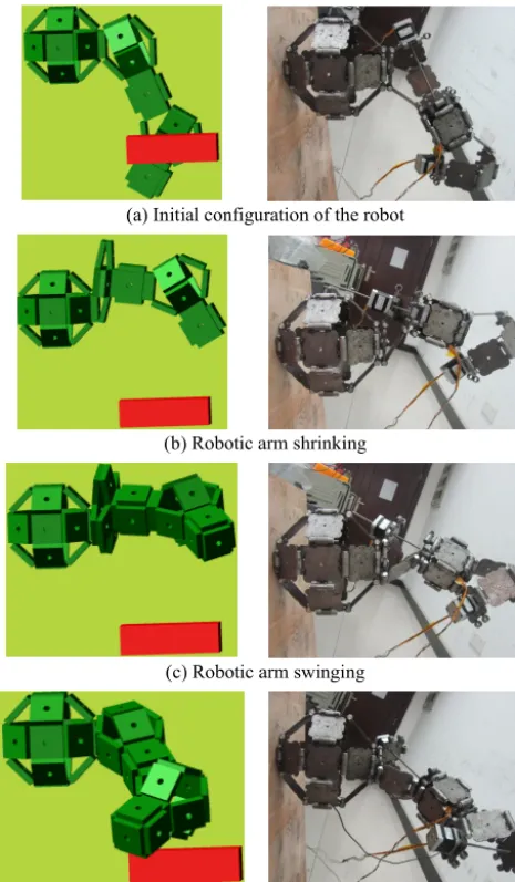
Figure 11.Obstacle avoidance motion test of the robotic arm.
It can be seen that if the shoulder joint rotates directly, the whole arm will swing toward the obstacle, which may lead to an interference between the arm and the obstacle. There-fore, in order to avoid potential collision with the obstacle, a simple but efficient motion control strategy is used based on the property of the Sarrus-linkage-based muscles. Figure 11a shows the initial configuration of the robot in simulation cor-responding with the physical test. By only driving the up-per arm Sarrus-linkage-based muscle, the upup-per arm shrinks and the arm arrives at a position over the obstacle, as shown in Fig. 11b. Following a rotation of the shoulder’s revolute joint, the robotic arm swings ahead and points in the front direction of the obstacle, as shown in Fig. 11c. Finally, by releasing the upper arm muscle, the upper arm expands to make the robotic arm reach the desired position avoiding the obstacle, as illustrated in Fig. 11d.
Initial tests indicate that the proposed robotic arm can not only perform the functions desired in the design but also overcome obstacles through the shrinking motion of the up-per arm and forearm Sarrus-linkage-based muscles, which greatly simplifies control strategy and reduces the financial cost for establishing complex control system.
5 Conclusions
In this paper, a novel bio-inspired robotic arm was for the first time proposed and presented. This robotic arm was designed and developed based on a single type of mechanical stem cells.
Inspired by the function and characteristics of the stem cell but different from the other robot “cell” or “molecule”, the mechanical stem cell presented in this paper is simple but capable of evolving into different functional cells, bones and muscles. Using the bones and a mechanical muscle de-veloped based on the Sarruse linkage, a 5-DOF bio-inspired robotic arm was designed and its associated kinematics was investigated. In order to solve the inverse kinematics of the proposed robotic arm, an optimization-method-based numer-ical iterative algorithm was proposed and verified with a nu-merical example and computer simulations. Further, a physi-cal prototype of the proposed 5-DOF robotic arm was devel-oped and initial tests were carried out to validate the correct-ness of forward kinematics and the applicability of inverse kinematics solving algorithm.
Overall, the paper has indicated that the stem-cell inspired pure mechanical stem cell has parallels in biology and pro-vides a flexible modular way to build mechanical bones and muscles for robotic arm development. Advantages of the pro-posed bio-inspired robotic arm can be summarized in three aspects: first, its structure is simple, modular and apt to be fabricated; second, its structure is reconfigurable and flex-ible; and third, the inner hollow space of these robot bones can be used to settle sub modules of robot, which is very use-ful for some special application such as space technology.
Author contributions. Designed and developed the robotic arm: Zirong Luo. Kinematics Analysis: Zirong Luo, Jianzhong Shang, Guowu Wei and Lei Ren. Simulation ad prototype: Zirong Luo, Jianzhong Shang. Wrote the paper: Zirong Luo, Jianzhong Shang, Guowu Wei and Lei Ren.
Acknowledgements. The author wishes to thank Ernest Ap-pleton, Bo Liao, Yunkai Yang and Jun Zhang for their valuable contributions in developing the prototype.
Edited by: K. Mianowski
166 Z. Luo et al.: Design of a bio-inspired module-based robotic arm using sarrus linkage
References
Acaccia, G., Bruzzone, L., and Razzoli, R.: A modular robotic sys-tem for industrial applications, Assembly Automation, 28, 151– 162, 2008.
Cai, Z.: Robotics, 2nd Edn., Tsinghua University Press, Beijing, 2009.
Chen, G., Zhang, S., and Li, G.: Multi-stable behaviors of compliant Sarrus mechanisms, J. Mech. Robot., 5, 021005, doi:10.1115/1.4023557, 2013.
Fukuda, T. and Kawauchi, Y.: Robotic system (CEBOT) as one of the realization of self-organizing intelligent universal manipula-tor, in: Proceedings IEEE Conference on Robotics and Automa-tion, Cincinnati, Ohio, 662–667, 1990.
Fukufda, T. and Nakagawa, S.: Dynamically reconfigurable robotic system, in: Proceedings IEEE Conference on Robotics Automa-tion, Franklin Plaza Hotel, Philadelphia, Pennsylvania, 1581– 1586, 1988.
Gavin, D. and Luis, R.: Biologically inspired telescopingactive sus-pension arm vehicle: Preliminary results, in: IEEE/ASME In-ternational Conference on Advanced Intelligent Mechatronics, Montreal, Canada, 1380–1384, 2010.
Guan, Y., Jiang, L., Zhang, K. X., Qiu, J., and Zhou, X.: 1-DOF joint modules and their applications in new robotic systems, in: IEEE International Conference on Robotics and Biomimetics, Bangkok, 1905–1910, 2009.
Guckert, M. and Naish, M. D.: Design of a novel 3 degree of free-dom robotic joint, in: IEEE/RSJ International Conference on In-telligent Robots and Systems, NJ, USA, 5146–5152, 2009. He, X., Kong, X., Chablat, D., Caro, S., and Hao, G.: Kinematic
analysis of a single-loop reconfigurable 7R mechanism with mul-tiple operation modes, Robotica, 32, 1171–1188, 2014. Jin, Z. and Gao, F.: Novel 6-SPS parallel3-dimensional platform
manipulator and its force/motion transmission analysis, Chinese J. Mech. Eng., 15, 298–302, 2002.
Katie, L. and Robert, J.: Myriapod-like ambulation of a segmented micro robot, Autonomous Robots, 31, 103–114, 2011.
Kotay, K. and Rus, D.: Locomotion versatility through self-reconfiguration, Robot. Autonom. Syst., 2, 17–23, 1999. Lee, C.-C.: Kinematic analysis and dimensional synthesis of
general-type Sarrus mechanism, JSME Int. J. Ser. C, 39, 790– 799, 1996.
Li, J., Zhang, G., Muller, A., and Wang, S.: A family of remote cen-terof motion mechanisms basedon intersecting motion planes, T. ASME J. Mech. Design, 135, 091009, doi:10.1115/1.4024848, 2013.
Liu, H., Huang, T., Mei, J., Zhao, X., Chetwynd, D. G., Li, M., and Hu, S.: Kinematic design of 5-DOF hybrid robot with largeworkspace/limb-stroke ratio, T. ASME J. Mech. Design, 129, 530–537, 2006.
Lu, T., Kang, Z., and Fang, X.: Numerical calculation method, Ts-inghua University Press, Beijing, 2008.
Ranjana, S., Srinath, A., and Richard, G.: Towards a 3g crawling robot through the integration of micro robot technologies, in: IEEE International Conference on Robotics and Automation, Or-lando, Florida, USA, 296–302, 2006.
Rus, D. and Vona, M.: Self-reconfiguration planning with com-pressible unit module, in: IEEE Proceeding of International Con-ference on Robotics and Automation, Detroit, MI, USA, 2513– 2520, 1999.
Sarrus: Note sur la transformation des mouvements rectilignes alter-natifsen mouvements circulaireset re ciproquement, Acad. Sci. C. R. Hebd. Seances Acad. Sci., 36, 1036–1038, 1853.
Shammas, E., Wolf, A., and Choset, H.: Three degrees-of-freedomjoint for spatial hyper-redundant robots, Mech. Mach. Theory, 41, 170–190, 2006.
Siciliano, B. and Khatib, O. (Eds.): Springer handbook of robotics, Springer-Verlag, Berlin, Heidelberg, 2008.
Wurst, K. H. and Peting, U.: PKM concept for reconfigurable ma-chine tools, in: The 3rd Chemnitz Parallel Kinematics Seminar, Zwickau, Germany, 63–66, 2002.
Xi, F., Xu, Y., and Xiong, G.: Design and analysis of a re-configurable parallel robot, Mech. Mach. Theory, 41, 2006. Yim, M., Duff, D., and Roufas, K.: PolyBot: a modular
reconfig-urable robot, in: Proceedings of the 2000 IEEE International Conference on Robots & Automation, San Francisco, CA, USA, 514–520, 2000.
Yoshida, K., Hata, N., Oh, S., and Hori, Y.: Extended manipulability measure and application for robot arm equipped with bi-articular driving mechanism, in: Proc. 35th Annu. Conf. IEEE Ind. Elec-tron. Soc., Porto, 3083–3088, 2009.