International Journal of Emerging Technology and Advanced Engineering
Website: www.ijetae.com (ISSN 2250-2459,ISO 9001:2008 Certified Journal, Volume 5, Issue 8, August 2015)
461
Network-on-Chip Architecture Based on Cluster Method
Raj Kumar.S
Assistant Professor, Department of Electronics and Communication
Dhanalakshmi Srinivasan College of Engineering Perambalur-621212,Tamilnadu,India.
Abstract - Most current on-chip networks utilize 2-D
mesh topology. As the number of the cores present on-chip is increasing rapidly, the diameter of the network-on-chip is also increasing rapidly, which leads to large delay and energy consumption. Small-World network is a new concept of networks. According to the property of the Small-World networks, this paper proposed a cluster based topology with long-range links. We introduce the cluster dividing method and the long-range links insertion algorithm, as well as the routing algorithm. Finally, we evaluate the performance of the topology proposed in this paper through simulations.
I. INTRODUCTION
With more and more transistors embedded on a chip, the SoC of bus structure is poor at scalability, flexibility, reusability, and programmability. As a rzesult the Network-on-Chip (NoC) [10] has been proposed and has gradually replaced the System-on-Chip of bus structure. Topology shows the connectivity and distribution of nodes which is a very important aspect to consider when we design an on-chip network. An appropriate topology can help to improve the performance of the on-chip network. Especially for a specific application, topology plays an important role in optimizing the performance of the network. Since different applications may have some different kind of communication requirements, general-purpose topology will be less efficient than application-specific designs. Therefore, in this paper, we will present a methodology of designing a topology for a specific application.
A. The Topology of 2-Dmesh
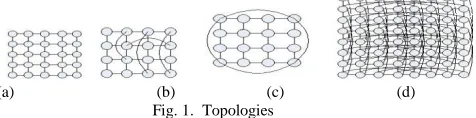
As 2-Dmesh has lower design complexity, most existing on-chip networks utilize 2-D mesh topology. As shown in Fig. 1(a), 2-D mesh has a regular and simple layout. However, the 2-Dmesh is not qualified to scale for their large diameter and energy inefficient [2]. Even if the shortest path routing algorithms are utilized, the large network diameter still leads to extra router hops, and the
router energy is much higher than the link energy [4]. In addition, traversing many hops between two remotely communicating nodes may also lead to higher message blocking probability. To solve these problems, two kinds of
solutions have been proposed,the long-range links
insertion algorithms and cluster based mapping algorithms.
B. Long-Rang Link Insertion
International Journal of Emerging Technology and Advanced Engineering
Website: www.ijetae.com (ISSN 2250-2459,ISO 9001:2008 Certified Journal, Volume 5, Issue 8, August 2015)
462
algorithms are complex[1], [5]. According to the insertion algorithm proposed by [1], we have to consider all the possibilities when we just insert one long-range link. After comparing the performance of all the inserting possibilities, a most efficient one is chosen. We have to repeat such complex computation each time we insert a range link to the networks. Moreover, since the long-range links insertion algorithms just take some couples of nodes into consideration, the whole network has not been mostly optimized, and it cannot guarantee the low energy consumption and traffic load balance.
C. Clusters Based Mapping Algorithms
To achieve low energy consumption and traffic load balance, some mapping algorithms [11] have been proposed.Especially in some mapping algorithms the nodes are divided into clusters [7][12]. When dividing the nodes, we have to consider two factors, the traffic volumes and physical shortest distance. As in [11], the paper proposed a fast topology partition based mapping algorithm for NoC. The purpose of the mapping algorithm is low energy consumption and traffic load balance. Through mapping algorithms, the performance of the network is optimized. But the diameter of the network is still large, and the performance of the remotely communicating nodes still has not been optimized. Furthermore, mapping algorithms usually cost a large amount of computation.
(a) (b) (c) (d)
Fig. 1. Topologies
D. Cluster Based Long-Range Links Insertion
Only considering the mapping or the long-range links inserting cannot mostly optimize the performance of the networks. Both of the ideas have their own advantages and limitations. So in this paper, we combine the two ideas, cluster based mapping and long-range links insertion, and we call this methodology “cluster based long-range links insertion algorithm”. This method does not need to take too complex computation. First, we divide the nodes into clusters and then we insert long -range links between two remotely communicating clusters. According to the characteristics of the Small-World networks, cluster and long -range links make the topology to be a Small-World network. Firstly, we divide all the nodes into 4 global clusters according to the traffic volumes. If there are still a large amount of nodes in a cluster, we divide the nodes in
the cluster into 4 small clusters further. That means the division is kept continuing until the bottom cluster is one of the unit clusters shown in Fig.2. Compared with other
algorithms, this dividing algorithm needs fewer
computations. After mapping the nodes onto a 2Dmesh, we
insert long-range links between two remotely
communicating clusters, such as, diagonal clusters. This algorithm can solve problems about large network diameter, node congestion, large energy consumption and latency.
[image:2.612.50.288.468.527.2]a. even unit b. odd unit
Fig. 2. Unit clusters
This paper is organized as follows. In section I, we will introduce some related works. In section II, we propose a new topology designing algorithm and elaborate the algorithm. We will introduce the routing algorithm of the topology proposed in section III. In section IV, we evaluate the performance of the topology.
II. RELATED WORK
International Journal of Emerging Technology and Advanced Engineering
Website: www.ijetae.com (ISSN 2250-2459,ISO 9001:2008 Certified Journal, Volume 5, Issue 8, August 2015)
463
we regard C as cluster coefficient. In a fully connected network, C=1. Assumed that the number of neighbors of node V is K, and the number of the links between K nodes
is lk , so the cluster coefficient of node V is:
C lv , C 1⋅
N
C (1)
∑
V
k v( kv−1) N V 1
V
2
The average length of shortest paths is a parameter of global nature. Usually Small-World networks have small
path length because of shortcuts. Iij is the length of the
shortest path between the node i and node j, so for a network, the average path length is:
L [
1
( N ( N −1))
] ∑ Iij (2)
i ≠ j
According to the properties of Small -world network, even only with the local information, we can find the shortest path. The advantages of Small-World should be considered to optimize the performance of network while designing a Small-World based topology.According to the nature of the Small-World networks, we propose a new method to design a NoC topology for a specific application. As the two basic principles of Small- World are clusters and shortcuts, we take both the cluster and long-rang links into consideration. We divide the nodes into clusters, and insert long-range links between remotely communicating clusters. We name this method as “Cluster Based Long-range Links Insertion Algorithm”.
III. CLUSTER BASED LONG-RANGE LINKS
INSERTION ALGORITHM
A.Background
The basic topology is m n 2Dmesh, as shown in Fig.
1(a). The nodes communicate with each other through the network. The process of designing a topology is shown in Fig.3. Firstly we get the communication graph. We compare the traffic volumes between the nodes, making the nodes whose traffic volumes distinctly larger a cluster. Then we insert the long links between two distant clusters.
Fig.3. Flow chart of insertion algorithm
A cluster can be composed of several cluster units. Usually we define 4 nodes or 9 nodes as a unit cluster, just as Fig. 2 shows. We define the 22 unit cluster as even unit cluster and 33 unit cluster as odd unit cluster. The diagonal links
are inserted to optimize the performance within a cluster. A network is composed of several clusters. For a large scale of networks, we can regard a small cluster as a node. In other words, a network can be made up of several clusters which are also composed of several low level clusters. The relationship between clusters in different levels is the iterative relationship.
0 0 0 0 0 0 0 0 0 0 00 0 00 0 700 0 0 0 0 0 0 0 0 00 0 00 0 0 3620 0 0 0 0 0 0 0 00 0 00 0 0 0 3620 0 0 0 0 0 0 00 0 00 0 0 0 0 3620 0 0 0 0 0 00 0 00 27 0 0 0 0 3570 0 0 0 0 0160 00 0 00 0 0 0 3530 0 0 0 00 0 00 0 0 0 0 0 0 3000 0 50000 0 00 0 0
00 0 0 0 0 0 3130 94 0160 00 0 00 0 0 0 0 0 0 3130 00 0 00 0 00 0 0 0 0 0 0 0 0 00 0 0160 0 0 0 0 0 0 0 0 0 0 16 0 0 00 0 0 0 0 0 0 0 0 0 0 0 0160 00 0 00 0 0 0 0 0 0 0 0 00 15700 0 0 0 0 0 0 0 0 0 0 00 0 160
0 0
[image:3.612.335.558.225.505.2]00 0 46 0 0 0 0 0 0 00 0 00 0
Fig. 4. VOPD Fig. 5. Traffic matrix TABLE I.THE NODES DIVISION
>350 2→3→4→5→6→7,10→8 300-350 7→8→9→10
100-200 13→14
0-100 1→2,4→16→5,12→6,10→9,12→9, 11→12→13→15,14→15→11
(a) the primary partition
(b)the final result
Fig.6. The partition of Nodes
B. The Partition of Clusters
For a specific application, we divide the nodes into 4 global clusters according to the traffic volumes and physical distance. For example, Fig. 4 is a communicating core graph of VOPD. To divide the nodes into four global clusters, first we get the traffic matrix as shown in Fig.5, then we draw a communication distribution according to the matrix, as shown in TABLE I. We make the first and second group as two clusters. Then we continue to divide the remaining nodes into clusters. For the VOPD application, the primary result is shown in Fig. 6 (a).
Finally we adjust the results to make the partition as simple
[image:3.612.79.262.620.658.2]International Journal of Emerging Technology and Advanced Engineering
Website: www.ijetae.com (ISSN 2250-2459,ISO 9001:2008 Certified Journal, Volume 5, Issue 8, August 2015)
464
long as we divide the nodes according to the traffic volumes, the result is reliable. Fig. 8 is a probable mapping result of 25 nodes, two odd clusters have a common node. Since appropriate partition and mapping can help to avoid
link congestion and reduce latency and power
consumption, the partition of clusters and mapping is very important
C. Long-Range Links Insertion Algorithm
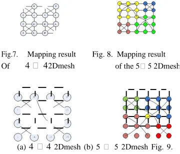
After mapping, we insert the long-range links between the remotely communicating clusters. To minimize the number of the long-range links inserted into the topology, firstly, we have to confirm which nodes to insert the long-range links. When choosing the nodes to insert the long-range links, we should take the acceptable length of long links into consideration. At the same time, if possible, the long-range links should be inserted into different nodes. Furthermore, we choose the nodes which have large traffic volumes with the remote clusters. Usually there is a need to insert long-range links between the diagonal clusters. Fig. 9 shows several results of long-range links insertion. The diameter of the network and the hops of the packets traveling from one cluster to the remote cluster have been reduced. As a result, the latency and power consumption also have been greatly reduced.
Fig.7. Mapping result Fig. 8. Mapping result
Of 4 4 2Dmesh of the 55 2Dmesh
(a) 44 2Dmesh (b) 5 5 2Dmesh Fig. 9. Topologies with long-range links
IV. ROUTING ALGORITHM WITH LONG -RANGE LINKS
The topologies with long-range links usually adopt deadlock free routing algorithm. We can also enumerate all the possible paths [3]. In this paper, to avoid deadlock [8], we utilize the deadlock detection and recovery mechanism.
The routing strategy proposed in this paper is based on the XY dimension -order routing algorithm. First we define the 4 clusters as 4 quadrants and name them with numbers (1 to 4). Within a cluster, the lower level clusters are also named as numbers according to the interior quadrants. As a result, the bottom quadrants of the unit clusters (level n) are named by n-dimension numbers. So the address of the
nodes can be expressed as q1 , q2, ,qn , x , y , x , y is the
coordinate in bottom cluster which represents the address
of the node in bottom cluster, q1 ,q2 ,...,qn is the address of
the bottom cluster, n is the depth of the cluster. When the packet arrives, we get the local and destination address. The comparison begins from the global quadrant number,
that means, first we compare the two q1 . If local q1 and
destination q1 are same which means the local node and
destination node are in the same global cluster ,we continue
to compare q2 , and this work continues until local qi and
destination qi are different. If q1 , q2, ,qn are all same, local
node and destination node hop between nodes while in this
topology, to see from level i which means qi is different,
packets hop between clusters in level i . We regard the
clusters in level i as nodes. Through default routing
algorithm (the XY dimension-order routing algorithm
extended with long- rang links), we get the path in level i .
To arrive the expected nodes along the path in level i , we
have to consider from level i − 1. In lower levels, we the
current destination is qi we have find the path in level i ,
and it is a progress of iteration. When q1 , q2, ,qn are all the
same, we utilize the default routing algorithm to lead the packet to the destination. The last, we have to apply the dead lock detection and recovery mechanism to avoid dead lock.
V. PERFORMANCE ANALYSIS AND SIMULATION
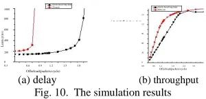
We evaluate the topology by simulating in the OPNET simulation platform. We observe the delay, throughput and energy consumption of the network. The energy
consumption of the network is defined as formula (3), Es is
the energy consumption of routers, El is the energy
consumption of links. As shown in formula (4), Ebiti,j is the
energy consumption of transmitting one bit from router ri
to router rj , Et is the total energy consumption of the
network, Ci, jisthe communication volume from router ri
to router rj , Nr is the number of routers along the path. We
[image:4.612.80.260.456.610.2]International Journal of Emerging Technology and Advanced Engineering
Website: www.ijetae.com (ISSN 2250-2459,ISO 9001:2008 Certified Journal, Volume 5, Issue 8, August 2015)
465
while the throughput has not been changed much. For the reduction of network diameter, the hops that link. The energy consumption is also reduced.
cluster based long links
1000 2D mesh cluster based long links 2Dm esh 150 800 Throughput(Gbit/s)
120
L
at
en
cy
(n
s)
600
90 400
60
200 30
0 0
0.61.2 1.8 2.4 3.0 0.3 0.6 0.9 1.2 1.5 1.8 0.0
Offerload(packets/cycle) Offerload(packets/cycle)
[image:5.612.94.244.181.253.2](a) delay (b) throughput
Fig. 10. The simulation results
VI. CONCLUSION
In this paper, we proposed a Small-World networks based topology. This topology combines mapping and long-range links insertion, which can greatly optimize the performance of the network.
REFERENCES
[1] U. Y. Ogras and R. Marculescu, “It's a small world
after all: NoC performance optimization via long-range link
insertion,” Very Large Scale Integration (VLSI) Systems,
IEEE Transactions, vol. 14, pp.693-706, 2006.
[2] C. H. O. Chen, et al., “Physical vs. Virtual Express
Topologies with Low-Swing Links for Future Many-Core
NoCs,” in proceedings of 2010 Fourth ACM/IEEE
International Symposium on Networks-on-Chip (NOCS),
pp. 173-180, 2010.
[3] P.P. Yue, J. Liu, S. Anjum, et al., “Enumeration-based
path allocation algorithm in NoC mapping,” Journal of
University of ElectronicScience and Technology of China,
vol. 37, no.1, pp. 54-57, 2008.
[4] F. Ge and N. Wu, “Low energy topology generation
approach for application-specific network on chip,” System
Engineering and Electronics, vol.32, no.8, pp. 1754-1759,
2010.
[5] U. Y. Ogras and R. Marculescu, “Application-specific
network-on-chip architecture customization via long-range
link insertion,” in proceed-ings of IEEE/ACM International
Conference in Computer-Aided Design, pp. 246-253, 2005.
[6] Y.Q. Sheng and W.Z. Kai, “An Improved Mesh
Topology and Its Routing Algorithm for NoC,” in
proceedings of International Confe-rence on
Computational Intelligence and Software Engineering
(CiSE),pp. 1-4, 2010.
[7] L. Zhonghai, X. Lei, and A. Jantsch, “Cluster-based
Simulated Annealing for Mapping Cores onto 2D Mesh
Networks on Chip,” in proceedings of 11th IEEE Workshop
on Design and Diagnostics of Electronic Circuits and
Systems (DDECS), pp. 1-6, 2008.
[8] B. Yang and S.-h. Xu, “The Analysis of Knowledge
Transfer Network Characteristic Based on Small-world
Network Model,” in proceedings of Second International
Conference on Future Networks, pp. 428-432,2010.
[9]
S. Jin and A. Bestavros, “Small-world characteristicsof the Internet and multicast scaling,” in proceedings of