© 2016, IRJET | Impact Factor value: 4.45 | ISO 9001:2008 Certified Journal | Page 812
FEA and Optimization of Tie Rod of motor vehicle
Mr. Pranav S. Kankarej
1, Prof. Anurag A. Nema
2,Prof. Anantharma
31
PG Student, M.E. Mechanical Engineering, Dhole Patil College of Engineering, Pune (M.S )[1]
23Asst. Prof. M.E. Mechanical Engineering, Dhole Patil College of Engineering, Pune(M.S.)[2]
---***---Abstract -
A car’s steering wheel is connected to steeringgear and steering gear is connected to wheels of vehicle via the tie rod ends. The tie rod end is used to ensure that the wheels are aligned. It provides the adjustment for wheel to align &keeps the tires free from wearing out on the inner as well as outer edges. Hence the functioning of tie rod is crucial for steering as well as suspension performance of vehicle. Today’s world is competitive. Market demands for the advanced technology at lower price. This reflects in making the technology cheaper. Hence every organization striving for cost effective product at a lower price and within minimum period for ‘time to market. This puts lot of pressure on engineers to consistently strive to design the more effective products at the lower price. The work is focus on functioning of the tie rod, the methods of its performance evaluation it’s optimization. Hollow Tie rod with 11.0mm ID is selected after analysis and further material analysis is done using 11.0 mm as ID. It gives 12.76% less weight than solid tie rod, without failure. Aluminum is suggested as applicable material after analysis.
Key Words: Tie rod, Weight optimization, hollowrod.
1.
INTRODUCTION
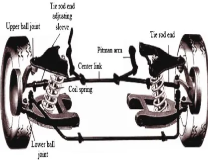
Design of suspensions components in an automotive is very critical as they are constantly under varying loads. While designing the component we must ensure the safety. Apart from design prospective it is important to focus on the weight and cost of an individual component. The tie rod is an important part of suspension system. It connects the steering to the suspension in order to transform the motion. Tie rods connect the centre link to the steering knuckle on automobiles having conventional suspension systems and recirculating ball steering gears, Fig. 1.1 On automobiles having MacPherson strut suspension and rack and pinion steering gears, tie rods connect the end of the rack to the steering knuckle, Fig. 1. A tie rod consists of an inner and an outer end as shown in both figures. Tie rods transmit force from the steering centre link (the rack gear) to the steering knuckle, causing the wheels to turn. The outer tie rod end connected to an adjusting sleeve, which allows the length of the tie rod to be adjustable. This adjustment is used to set a vehicle toes. A critical alignment angle, sometimes referred to as the caster and camber angles. A vehicles steering as well as
suspension system should be checked regularly, at least once a year along with a complete wheel alignment.
[image:1.595.326.535.317.478.2]Tie rod end can be worn due to rubbing and wearing. This can cause wandering, erratic steering and excessive tire wear. Wheel alignment is necessary if the tie rod is replaced because tie rod replacement disturbs the toe setting.
Fig. 1.1: Conventional suspension
There are several applications where a tie rod is utilized to help secure and support equipment on an automobile and aircraft like as on the fuselage of an airplane. These are purely structural members. A robust knowledge of the design loads is required to ensure that the part will satisfy its proper functioning on the automobile and aircraft. In certain cases, these tie rods required to be designed for buckling at a specific load to avoid puncturing or damage of nearby components. Based on the design criteria of minimizing compression margin, safety coupled with the degree of difficulty to predict buckling behavior, an accurate calculation of the critical buckling load is required.
2.
LITERATURE REVIEW
© 2016, IRJET ISO 9001:2008 Certified Journal Page 813
between the theoretical and actual physical tests.
This error is accounted for improper boundary
conditions, selection of proper element type, analysis
approach. Increasing the accuracy of modeling would
lead to more accurate results and correlation. Factors
affecting the buckling performance of any structure
should be done primarily before designing the any
part against the buckling load. Even before using the
FEA software. As mentioned earlier; tie rod is mostly
under dynamic loading conditions. Most of the
research papers only focused on static buckling
loading. The dynamic nature of loading should be
considered because if the material and length are
constant the cross sectional shape can be parameter
that decides the inertia and mass. In case of large
structures FEA solver often takes large time to solve.
This issue is especially critical in case of nonlinear
analysis. The use of parallel and/or distributed
processing of memory is need to be incorporated in
the analysis. Convergence issue is very critical in case
of nonlinear analysis. Most of the times the run
completed for 60 to 80% of loading and exited due of
non-convergence. Solution has be provided for this
kind of issue. What are the considerations user
should follow before starting the analysis has to be
mentioned. This is because in case of large models,
which takes 12 to 20 Hrs. convergence issue is
critical. Because if after 12 hours if it is found that the
solution has not been converged, then this ends up in
loss of time. Use of Superelement can be also useful
in case of large models; where the local buckling
modes are found in the model.
3. PROBLEM DEFINITION
The existing tie rod is assembled using three different parts. Hollow, solid and ball joint. This is quite complex design. Due to larger length of solid part the design has become bulky and less efficient in terms of load carrying capacity. There are chances of failure at the critical locations like notch, joints, fillets etc. As the tie rod is continuously under random loading there can be more chances of developing the cracks at the critical areas and chances of failure. Also the manufacturing process of this existing design is critical and time consuming. Hence it is necessary to make the design simple and cost effective such that it gives overall effectiveness in terms of weight, cost, load carrying capacity and easy of manufacturing process. The main task in this study is to find the critical buckling load for the existing design. Observe the deformation and stresses induced in the Tie rod. Set up the benchmark for the proposed design. Try to evaluate the possibility with different material combinations for optimized design. Target is to obtain the design such that
critical buckling load will remain same with reduced weight of tie rod. The stress targets are also need to be achieved. Pre-processing will be carried out using finite element analysis software named ANSYS. The results will be compared with practical and theoretical results. From the variables optimized tie rod will be selected and evaluated.
Objectives:
An objective of this work is that the performance evaluation of an existing tie rod. This is done in terms of displacement, stress, and strain analysis. Evaluate sensitivity of structure against different input parameters (Tie rod dimensions/materials). Decide the optimization scope for weight reduction. Construct the design of new optimized model. Take the necessary physical tests on the tie rod in order to validate it against the actual physical conditions.
4. METHODOLOGY
Design:
Instead of directly starting with modeling, firstthe dimensions are provided by company are to be calculated as per company design guideline. Calculate all necessary dimensions to design the Vessel. After verifying the all dimensions starts modeling by in Workbench and further analysis will be carried out by using Ansys software. Calculatedall values by using Following ASME Code details.
Analysis:
Following are the steps in ANSYS for analysis of Tie Rod, Analysis Type: Static Structural
Engineering Data: Selection of material and material properties
Model: Drawing the model in ANSYS Workbench
Meshing: Discretization of Tie Rod
Boundary Condition: Apply boundary condition (Force)
Solve: Solving for Getting Von-mises stresses and deflection.
Experimental:For the validation of result obtained by
the FEA software, experimentation is to be carried out on the actual model. Using the accelerometer and HMI (Human machine interface) equipment for experimental testing and then the results of this work are used for the validation of results obtained from analysis software.5. MODELLING AND ANALYSIS OF EXITING TIE
ROD
© 2016, IRJET ISO 9001:2008 Certified Journal Page 814 Fig 5.1: CAD model of Tie Rod
Fig 5.2: Weight of Tie rod (Solid)
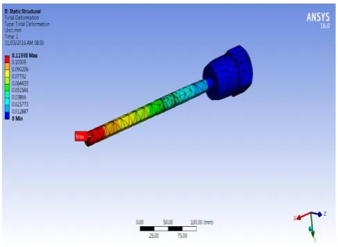
[image:3.595.320.551.415.576.2]Fig 5.3: Result for Deformation
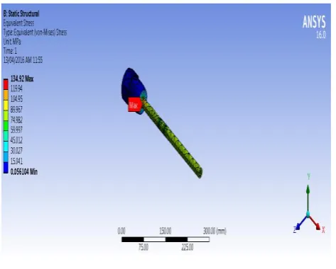
Fig 5.4: Result for Von-mises stresses
6. RESULTS BASED ON ANALYSIS CARRIED OUT
FOR VARIOUS ID’S (Hollow Shaft)
6.1 Sample Analysis for ID 9.0 mm:
[image:3.595.40.284.432.610.2]© 2016, IRJET ISO 9001:2008 Certified Journal Page 815 Fig 6.2: Stress in Tie Rod
Fig 6.3: Deflection in Tie Rod
Similarly analysis is done for various ID’s and results are given in below table 6.1:
ID, mm
Thicknes s, mm
Stress, MPa
Deflection, mm
Weight, kg
Solid -- 105.04 0.11598 1.756
9.0 4.5 134.92 0.12063 1.606
9.50 4.25 143.1 0.12156 1.589
10.0 4.0 154.11 0.13091 1.571
10.50 3.75 162.76 0.13219 1.552
11.0 3.50 174.56 0.13897 1.532
11.50 3.25 194.43 0.13163 1.511
12.0 3.0 216.03 0.14625 1.489
Allowable Stress = Yield / FOS = 360/2.0 = 180.0 MPa
From above results we can see that with ID 11.0mm the stresses generated are within allowable and hence is suggested for further work.
7. MATERIAL ANALYSIS RESULTS
Table 7.1: Results of material Analysis
Material Stress, MPa
Deflection, mm
Weight, kg
Allowable Stress, MPa
Steel 174.56 0.13897 1.532 180.0
Alumi-num 175.47 0.39121 0.5282 177.5
Cast Iron 173.94 0.25277 1.4033 184.0
-From the above result it can be seen that for weight condition Aluminum gives us better result without failure, hence can be used for alternative to existing material. Cost of material is less compare to Steel and Cast Iron.
-For case of Reliability and life Steel is better (Weight on higher side).
-CI is good in strength, higher in weight compare to Aluminum. Cost of CI is on higher side.
Depending on requirement material can be selected. Here for the selected application Steel is recommended by Industrial experts.
8.
Optimized Rod Modal Analysis:
Modal analysis was performed on optimized model of tie rod to determine critical natural frequency of tie rod and to avoid resonance.
Table 8.1 Natural Frequencies of Optimized Model
Mode Frequency [Hz]
1. 106.21
2. 109.26
3. 517.53
4. 1015.0
5. 1033.6
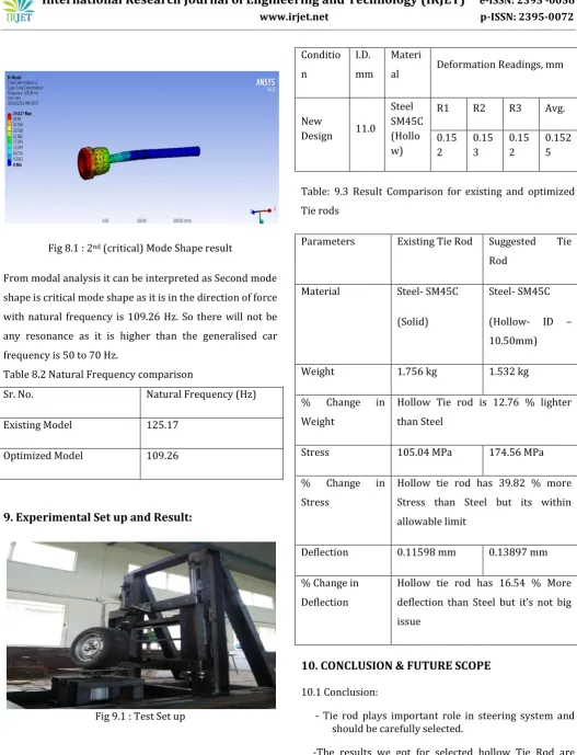
© 2016, IRJET ISO 9001:2008 Certified Journal Page 816 Fig 8.1 : 2nd (critical) Mode Shape result
From modal analysis it can be interpreted as Second mode shape is critical mode shape as it is in the direction of force with natural frequency is 109.26 Hz. So there will not be any resonance as it is higher than the generalised car frequency is 50 to 70 Hz.
Table 8.2 Natural Frequency comparison
Sr. No. Natural Frequency (Hz)
Existing Model 125.17
Optimized Model 109.26
9. Experimental Set up and Result:
Fig 9.1 : Test Set up
Table 9.2: Experimental Results
Conditio n
I.D. mm
Materi
al Deformation Readings, mm
New
Design 11.0
Steel SM45C (Hollo w)
R1 R2 R3 Avg.
0.15 2
0.15 3
0.15 2
0.152 5
Table: 9.3 Result Comparison for existing and optimized Tie rods
Parameters Existing Tie Rod Suggested Tie
Rod
Material Steel- SM45C
(Solid)
Steel- SM45C
(Hollow- ID – 10.50mm)
Weight 1.756 kg 1.532 kg
% Change in
Weight
Hollow Tie rod is 12.76 % lighter than Steel
Stress 105.04 MPa 174.56 MPa
% Change in
Stress
Hollow tie rod has 39.82 % more Stress than Steel but its within allowable limit
Deflection 0.11598 mm 0.13897 mm
% Change in Deflection
Hollow tie rod has 16.54 % More deflection than Steel but it’s not big issue
10. CONCLUSION & FUTURE SCOPE
10.1 Conclusion:
- Tie rod plays important role in steering system and should be carefully selected.
© 2016, IRJET ISO 9001:2008 Certified Journal Page 817 - Hollow Tie rod with ID 11.0mm is selected for
optimization purpose.
- Overall (Compare to existing model with solid steel rod) change in weight is 12.76 % for Steel- hollow tie rod.
10.2 Future Scope:
- Dynamic Analysis can be done.
- Transient Analysis can be scope for further work.
11. References
[1] A.H. Falah & et al., “Failure investigation of a tie rod end of an automobile steering system” at Elsevier, Engineering Failure Analysis 14 (2007) 895–902. [2] Wei Duan & et al., “Failure analysis of threaded
connections in large-scale steel tie rods” at Elsevier, Engineering Failure Analysis 18 (2011) 2008–2018.
[3] Soohyun Nam & et al., “Development of the light weight carbon composite tie bar” at Elsevier, Composite Structures 134 (2015) 124–131. [4] Manik A. Patil & et al., “FEA of Tie Rod of Steering
System of Car” at IJAIEM, Volume 2, Issue 5, May 2013, ISSN 2319 – 4847.
[5] NerioTullini & et al., “Bending tests to estimate the axial force in tie-rods” at Elsevier, Mechanics Research Communications 44 (2012) 57– 64. [6] M. Amabili & et al., “Estimation of tensile force in
tie-rods using a frequency-based identification method” at Elsevier, Journal of Sound and Vibration 329 (2010) 2057–2067.
[7] MalgeSangeeta & et al., “Performance of the Structural Analysis of Ford CarSteering Rod” at IJRAT, Volume 2, Issue 2, February 2014, E-ISSN 2321-9637.
[8]
H.R. Kim & et al., “A study of the manufacturing of
tie-rod ends with casting/forging process”at Elsevier, Journal of Materials Processing Technology 125–126 (2002) 471–476.[9]
P. M. Chavan & et al., “Performance evaluation of
passenger car tie rod using numerical and theoretical approach with different materials” at IJRET (2014) eISSN: 2319-1163 | pISSN: 2321-7308.[10] D.H. Kim, “Modification of hypoeutectic Al-Si alloy by strontium”, J. Korea Foundrymen’s Soc. 15 (3) (1997) 138-141.
[11] G.L. Sheldon, “Unusual failure of an automobile steering component, in failure prevention and reliability conference”, Dearborn, Mich., USA, 1983, p. 27-31.
[12] B. Kenny, “Load and stress distribution in screw threads”, Exp Mech 1985, 25(3), 208-13.
[13] D.L. Miller, “Determination of load distribution in threaded connection”, Mech Mach Theory 1983, 18(6), 421-30.
BIOGRAPHIES
Mr. Pranav S. Kankarej received the bachelor of Engineering from G.H. Raisoni College of Engg. & Management, Wagholi, Pune in 2013. He is now pursuing M.E. in Design Engineering from Dhole Patil College of Engg. Pune.
Prof. Anurag A. Nema is allied with Dhole Patil College Of Engineering Pune, department of mechanical engineering as Assistant Professor. He had completed his M. Tech (CAD CAM) from Rashtrasant Tukadoji Maharaj Nagpur University in 2009. The author is associated with teaching from 10 years. His area of interest is Computer Aided Engineering fixture design, NVH, Vibration Measurement.