© 2015, IRJET.NET- All Rights Reserved
Page 754
Design and Verification of High performance Aligning-Dividers and Its
Testing by BIST Method
Bhanu Rekha.S
1, Jayakumar.R
2, Chandrashekar.H
31
M.tech student, Department of Electronics and Communication (PG), VEMU IT, Andhra Pradesh, India
2
Ass Prof, Department of Electronics and Communication, VEMU IT, Andhra Pradesh, India
3Asst
Prof, Department of Electronics and Communication, VEMU IT, Andhra Pradesh, India
---***---Abstract-
With the increasing demand for fastercomputing methods that are also optimum in power and area constraints, it becomes necessary to look at approaches that enhance the existing operations or bring out new methods to satisfy the constraints. A SRT or a digit recurrence schemes tend to use a larger look up table to store the quotient digit this results in a large area, missing of bits while transferring to hardware and also increase the overall size of the design, hence cannot be incorporated in smaller devices like signal processors, cryptographic processors and floating point units, to overcome this drawbacks the proposed method uses a different approach so called Data Dependent Dividers[2][7], which aims to develop and design of various data dependent architecture such as the Self aligning, Direct aligning and the Hybrid aligning architectures, which execute in variable time and also tend to use lesser number of resources that is in terms of flip-flops, adders and MUXes, which are the important resources of FPGA[9].
The proposed work attempts to bring out the advantages of the above mentioned dividers, over one another. An algorithm for self testing the circuit for functionality using BIST is designed. The proposed work has been classified broadly into two parts1. Non-floating point dividers – includes three algorithms, namely Self-Aligning Division, Direct-Aligning Division and Hybrid aligning division and brings out the differences, the advantages and disadvantages of each; 2. BIST – A circuit self-test to test any of the non-floating point dividers. All algorithms developed is synthesizable and are targeted for vertex 5 FPGAII.
Key Words:
Self-Aligning Division, Direct-AligningDivision, Hybrid aligning division, BIST (built-in self test)
,
SRT etc…
1. INTRODUCTION
Division is the most complex of the four basic arithmetic operations and, in general, does not produce an exact answer, since the dividend is not necessarily a multiple of the divisor [6]. Therefore, the corresponding quotient and
remainder are usually obtained through performing a sequence of iterations until the desired precision is reached. This procedure is called sequential division and serves as the basic principle for many practical implementations Based on sequential division, the most prevalent representatives are radix-β dividers, Where β denotes the radix, typically chosen to be a power of 2.In order to compute the answer, many of these dividers perform a constant number of iterations, which makes them very attractive for fully pipelined architectures. However, several concepts have been developed to speed up the exhaustive sequential process.
Hardware dividers are needed in many areas of applications like cryptography, signal processing, communication systems, computer floating-point units, etc. The performance requirements of these applications differ regarding data and architectural issues. High-speed dividers[1] are usually too large in area to be incorporated in small architectures Like signal processors. This circumstance and the rapidly growing demand for small and fast hardware dividers greatly encourage the search for more sophisticated solutions.
Regarding practical implementations of sequential division, there are two fundamental concepts: the subtract-and-shift approach and division by multiplication. The first method addresses the technique of performing successive subtractions and shifts, which serves as the underlying principle for all dividers proposed in this paper
1.1
Built In Self Test(BIST)
© 2015, IRJET.NET- All Rights Reserved
Page 755
their own circuits, thereby reducing dependence on anexternal Automated Test Equipment (ATE).
The main advantages of implementing BIST are lower cost of test, since the need for external electrical testing using an ATE will be reduced, if not eliminated; better fault coverage, since special test structures can be incorporated onto the chips; shorter test times if the BIST [4][10] can be designed to test more structures in parallel; it’s capability to perform tests outside the production electrical testing environment. This allows the users to test the chips prior to mounting or even after these are in the application boards
1.2 Hardware Description Language
HDLs are used to write executable specifications for hardware. A program designed to implement the underlying semantics of the language statements and simulate the progress of time provides the hardware designer with the ability to model a piece of hardware before it is created physically. It is this executability that gives HDLs the illusion of being programming languages, when they are more precisely classified as specification languages or modeling languages.
Hardware Description Languages include VHDL [6], Verilog [5], System C and Handle-C are frequently used for FPGA programming. VHDL and Verilog are matured as industry standards. Behavioral, RTL and structural levels of description can be used inter-changeably in these languages. Synthesis tools for System C are emerging, but do not approach the maturity of VHDL or Verilog synthesis products. Among the hardware description languages mentioned, a mix of VHDL and verilog is used.
2. RELATED WORK
SRT [2] is named after its inventors Sweeney, Robertson and Tocher In their method,
1/2 <|D|<1
is assumed, which means that the divisor is a normalized fraction in the form 0.1d2 . . .dn
Also assumed as
1/2<|2R(j)<1,|
This means that all the partial dividends are normalized fractions.
qj+1ϵ{-1,0,1}
now here the divisor is shifted or added to or subtracted from the partial dividend
2.1. RESTORING DIVISION: 0 ≤R
(j+l)< D
In the conventional restoring division 0 ≤R (j+l) < D The quotient digit qj+l, j = 0, l. 1. n - 1 is selected by performing a sequence of subtractions and shifts. Each time D is subtracted from the partial remainder r x R (j), until the difference becomes negative. Then D is added back to that negative difference, which is so called restoring. The last
subtraction is canceled by the addition here. the quotient digit, which is determined by the number of subtractions as qj+l = (number of subtractions -1). In general: qj+l + 1 subtractions and 1 addition are required to find qj+l in the worst case. Figure 3.3 shows an example. For a binary number system in which r = 2, the worst case scenario can be greatly improved.
R (j+l) = r x R (j) - qj+l x D Becomes
R (j+l) = 2R (j) - qj+l x D,
With qj+1∊ (0, l}, 0 ≤R (j+l) < D The quotient digit can be determined as follows
Fig: 2.1.Example of Restoring Procedure
The partial remainder can be obtained by one left shift of
R (j), and the trial process can be implemented by one
subtraction:
R (j+l) = 2R (j) - D.
Then the “sign” of R (j+l) is checked ,If it is positive, qj+l = 1, else qj+l = 0 and one restoring [1] addition is to be performed. So the binary restoring division requires at most one subtraction and one addition to determine one quotient digit. The addition is needed to restore the correct partial remainder:
R (j+l) = R (j+l) + D = 2R (j).
© 2015, IRJET.NET- All Rights Reserved
Page 756
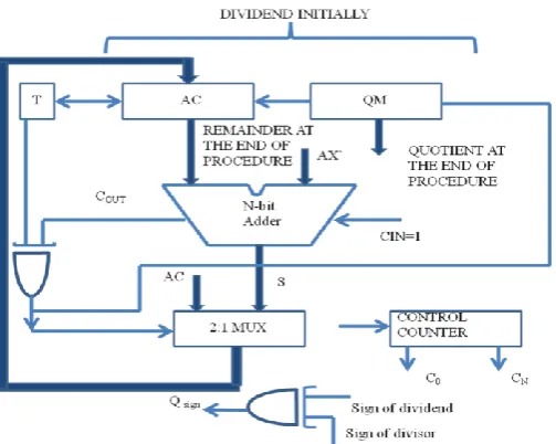
initially stored in registers AC concatenating QM. The n-bit [image:3.595.38.290.263.464.2]divisor is stored in the AX register. The content of AC concatenating QM can be left shifted. The quotient digit qj+l can be shifted in from the right end, and the bit shifted out from the left end of AC can be stored in a buffer register T.It can be seen that the similar hardware performing multiplication can be applied for division except the differences made on the following issues. First, the direction of register shift was shift to right in multiplication, while in division it is shift to left. Second, the adder actually performs subtraction now, that is add the 2’s complement number of the divisor. In Figure 2.2, the input AX’ to the right side of the Adder is
Fig: 2.2: Hardware Of Restoring Logic
the 1’s complement of the dividend.
With the Cin, set to 1, AC +AX ‘+ 1 = AC – AX this is choosen to inspect whether 2R (j) is < D or ≥ D. Cout is the carry out. Quotient digit q j+l is obtained by Qj+l = T v Cout.
2.2 Binary Non-Restoring Division|R (j+l) |≤|D |
An improved division method is the binary non-restoring division which does not need the “restoring addition” mentioned previously. The assumption that D > 0 and |R
(j+l)| < D remain the same, while the partial remainder, R
(j+l), is allowed to have either a positive or a negative value.
The operation to be performed can be either subtraction or addition, depending on the partial remainder.
The binary non-restoring division (B.N.D.) is performed in Figure 2.2 in contrast to the binary restoring division (B.R.D.) of that shown in Figure2.3.in the binary non-restoring division, no restoration is needed and thus the MUX in Figure 3. 4 can be eliminated. Consequently, the division time is improved.
Fig2.3: Division Performed By Non-Restoring Algorithms
3. Alinging Dividers
The integer divider becomes the back bone of any divider whether floating point or non floating point because even in floating point divider there is a integer divider operating on mantissa and adders acting on exponents. there exists architectures like SRT[1] where in they use look up tables for selection of quotient and remainder, as the radix increases there is a tendency in increase in look up table size which ultimately requires more area, to avoid such look-up based design it is precise to go for data dependent dividers so called aligning dividers.
Non-floating point dividers are those that take two integer values as inputs for the dividend and divisor and produce the result in two parts, namely the quotient and the remainder. Among non-floating point dividers, the paper explore three algorithms in particular:
1. Self-Aligning Divider 2. Direct-Aligning Divider 3. Hybrid-Aligning Divider
© 2015, IRJET.NET- All Rights Reserved
Page 757
3.1. Self-Aligning DividerThe usual methods of division involve shifting the divisor right in iteration and subtracting it from the dividend repeatedly until the process is completed. In the self aligning divider, these steps are preceded by the process of alignment. This involves aligning the divisor with respect to the dividend
3.1.1. The Self-Aligning Division Algorithm
The algorithm for the self-aligning divider is no doubt a combination of the above explained steps, namely, alignment and iterative subtraction.
Hence the overall algorithm of self-aligning divider can be summarized as follows.
1. Store the dividend in a register R, the divisor in register HW (higher word) and the constant (0000 0001)2 in LW (lower word).
2. Set a bit M to indicate the carry out (CO) in shift operations. Initialize M to 0.
3. For alignment, perform subtraction as R-HW, and store the carry out bit of the twos complement addition. 4. Shift HW and LW left by one bit and add 0 to LSB of LW, store Most Significant Bit in M
5. If M=1 or CO=0, alignment is complete, hence go to step 6. If M=0 and CO=1, then the alignment is still in progress, hence continue the next iteration and go back to step 3. 7. For subtraction, shift HW and LW to the right by one bit and store the Least Significant Bit in M
8. Perform subtraction as R-HW and store the carry in CO. 9. If CO=1, the result is positive, hence store the result of subtraction in R. If CO=0, the result is negative, hence retain the previous value of R.
10. Shift HW and LW right and store LSB in M
11. If M=1, stop division, else return to step 7 to proceed with the next iteration.
The quotient bit in each iteration is stored as the Most Significant Bit of the register in which the count value is initially stored.Hence,with each iteration in the subtraction, the register is shifted to the right. This would mean that the latest quotient bit is stored to the left of the previous quotient bit. Generally, the result is stored with each bit being written o the right of the previous bit. Since this is just the opposite of what happens in the self-aligning division procedure, it indicates that the quotient is stored in the reverse order as compared to what is required. Hence there is a requirement to reverse the quotient after obtaining the final result.
3.1.2. Block Diagram of the Self-Aligning Divider
From the algorithm mentioned, a simple block diagram of the self-aligning divider can be developed as shown in fig 3.1.In the block diagram, the registers are as follows:
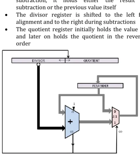
The remainder register initially holds the dividend before alignment. After alignment, it
holds the aligned value of dividend. In subtraction, it holds either the result of subtraction or the previous value itself
The divisor register is shifted to the left for alignment and to the right during subtractions The quotient register initially holds the value ‘1’
[image:4.595.318.549.117.371.2]and later on holds the quotient in the reverse order
Fig. 3.1. Block Diagram of the Self-Aligning Divider
An example of the self-aligned division is shown below. Example 1: 200/18 = 11+2 in decimal Or
1100 1000 / 0001 0010 = 0000 1101 + 0000 0010 in binary
R HW LW 1100 1000 0001 0010 0000 0001 +1110 1110
(1) 1011 0110 0010 0100 0000 0010 1100 1000
+1101 1100
(1)1010 0100 0100 1000 0000 0100 1100 1000
+ 1011 1000
(1)1000 0000 1001 0000 0000 1000 1100 1000
+0111 0000
(1) 0011 1000 (1) 0010 0000 0001 0000 1001 0000 0000 1000 1100 1000 0111 0000
(1) 0011 1000 0100 1000 1000 0100 0011 1000 0100 1000 1000 0100 1011 1000
(0) 1110 0000 0010 0100 0100 0010 0011 1000
1101 1100
(1) 0001 0100 0001 0010 1010 0001 0001 0100
1110 1110
© 2015, IRJET.NET- All Rights Reserved
Page 758
3.2. Direct-Aligning DividerDesigning a first divider that integrates the aligner is a pretty straightforward task. The generated divisor is always aligned correctly to the partial remainder regarding data sizes. However, both operands might contain any possible combination of trailing bits after the leading non-zero bit
The algorithm for direct-aligning divider can be summarized in the following steps:
1. Store the dividend in registers S1 and S2 2. Store the divisor in register AD
3. Store the binary value (00000001 )2 in register PQ
4. Align divisor AD and register PQ with respect to dividend S1 by shifting left 5. Shift AQ once to the right and store the
resulting value in PQ
6. Perform the subtractions: S1-AQ and S2-PQ and store the carry out CO and the result of the subtraction in register T1 and S 7. If CO = 1, store S in S1 and S2, else shift AD
and PQ once to the right and store S2 in S1 8. Perform OR operation of PQ and Q and
store the result in Q to get the updated value of the quotient
9. Align AD and PQ by shifting right and store LSB of PQ in bit M
10. Repeat steps 6 through 10 till the subtraction in right alignment gives negative bits to be shifted
Alignment
1. For initial left alignment, find the position of the first 1 in S1 and AQ, and find the difference between the two positions
2. If the difference is positive, shift left the divisor AD and PQ by the difference number of positions
3. For right alignment during division, find the difference of the position of the first one in S1 and AD. If the difference is positive, shift the divisor right by those many bits, otherwise, division is complete.
This method of using two adders in parallel is realized in the direct-aligning (DA)[2] divider shown in Figure 3.2. Note that the design does not contain a 2n-bit shift register, and therefore, theoretically any available registers can be utilized. Adder 1 is supplied with the full n-bit inverted AD as second operand, whereas Adder 2 is supplied with a constant non-zero MSB combined with the n-1 high-order bits of the inverted AD, which implies a wired right-shift by one position. The CO signal of Adder 1 is used to control the two multiplexors. In case the primary subtraction underflows, mux 1 selects the result of Adder 2 and mux 2 selects the right-shifted PQ, which is OR-ed with the quotient register.
Fig. 3.2. Schematic Diagram Of Direct-Aligning Divider
The operational sequence of the DA divider is illustrated in Example 2, again, for solving 200/18 = 11 + 2.
Solving 110010002/100102 = 10112 +102 with direct-aligning divider. Note that AD and PQ are produced by pure combinational logic.
R (S1) R(S2) AD PQ Q
1100 1000 1100 1000 ………. ………. 0000 0000 1100 1000 1100 1000 1001 0000 0000 1000 - 1001 0000 - 0100 1000
(0)0011 1000 1000 0000
0011 1000 ………. ………. 0000 1000 0011 1000 0011 1000 0010 0100 0000 0010
- 0010 0100 - 0001 0010 (0)0001 0100 0010 0110
0001 0100 ………. ………. 0000 1010 0001 0100 0001 0100 0001 0010 0000 0001
-0001 0010 -0000 1001 (0)0000 0010 0000 1011
0000 0010 ………. ………. 0000 1011
3.2Hybrid Aligning Divider
The direct aligning divider uses only n iterations while compared to 2n iteration in case of self aligned divider. but the execution time is increased further in case of direct aligning divider this worst case execution time can be reduced by the use of hybrid aligning divider, that is by making the worst case delay to become fast, this can be achieved by invoking the two adders in a short critical path instead of invoking them in extended aligner path. this is done by using temporary registers and multiplexors this is as shown in figure 3.3.
© 2015, IRJET.NET- All Rights Reserved
Page 759
Solving 110010002/100102 = 10112 +102.Note that AD andPQ are stored in temporary registers.
R(S1) R(s2) AD PQ Q Step
1100 1000 1100 1000 -1001 0000 1100 1000 1100 1000 -0100 1000 00000000 10010000 0000 0000 0000 1000 0000 0000 Load dividen d into R, reset all load AD and PQ into register s Subtrac t AD and {0,AD[7 :1]} (0)001 11000 0011 1000 -0100 1000 (0)100 00000 -0010 0100
01001000 0000 0100 0000 1000 S1 is positive , select PQ, write S1 shift AD and PQ Subtrac t AD and{0:A D[7:1]} (1)111 10000 -0010 0100 (0)000 10100 0001 0100 -0001 0010 00100100 0000 0010 0000
1010 S2 is positive ,shift PQ first write S2 shift AD Subtrac t AD and {0AD[7: 1]} (1)111 10000 (0)000 00010 0000 0010 00010010 0000 0001 0000
1011
S2 is positive , shift PQ first write S2,R<D =Done
Temporary registers
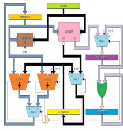
The two temporary registers are capable of performing a wired right shift through a multiplexor, it is loaded with the existing AD and PQ generated from the aligner ,and from now on the divider works with the contents of TR's, which are loaded-shifted during each subtraction. the CO
[image:6.595.333.545.152.378.2]signal is used to control the MUX which is the carry out from the adder.
Fig 3.3 Hybrid aligning divider
if the initial subtraction doesn't underflows then the quotient register is written before the PQ-TR and the contents of PQ-TR or OR-ed with the quotient register. the ambiguity of whether PQ-TR is sifted before or after its contents is used is decided by the control signals generated from the two adders which are NOR-ed to control the MUXes which are responsible for loading and shifting the temporary registers.
Parallel Adders
the adders[8] are initiated in the short critical path by using the contents of AD-TR until the secondary subtraction also underflows, in such case the TRs are loaded with the contents form the aligner this results in deriving a new partial remainder without an iteration
4. BIST Implementation
A generic approach to BIST is shown in Figure 4.1. On a very basic level, BIST needs a stimulus (the Test Pattern Generator (TPG))[10], a circuit to be tested (CUT) and Output Response Analyzer (ORA)- a way to analyze the results, and a way to compress those results for simplicity and handling. However, BIST designs can differ in many ways. Each method has its own set of tradeoffs and design considerations.
© 2015, IRJET.NET- All Rights Reserved
Page 760
however, remains more or less as what is shown in thefigure 4.1.
Fig 4.1.General structure of BIST.
5. SYNTHESIS AND SIMULATION RESULTS
The various simulations and outputs that have been performed for the circuits designed, coded and implemented and the outputs thereof are illustrated here. All the simulations are carried out with the following environmental setup:
Operating System: Microsoft Windows XP(Professional & Home Edition)
Coding Language: VHDL
Software Tool: Xilinx version 12.4
Simulator: Xilinx ISE
Specifications used for simulation:
Dividend, Divisor, Quotient, Remainder 8 bit binary numbers
Family: Virtex 5
Device: Virtex 5 : XC5VLX30T
Hadware tool:ULK Kit,FPGA-Virtex.
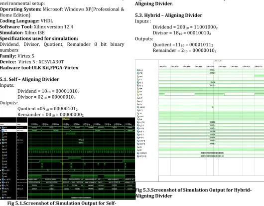
5.1. Self – Aligning Divider
Inputs:
Dividend = 1010 = 000010102 Divisor = 0210 = 000000102 Outputs:
Quotient =0510 = 000001012 Remainder = 0010 = 000000002
Fig 5.1.Screenshot of Simulation Output for Self-Aligning Divider
5.2. Direct – Aligning Divider
Inputs :
Dividend = 20010 = 110010002 Divisor = 1810 = 000100102 Outputs:
Quotient =1110 = 000010112 Remainder = 210 = 000000102
Fig 5.2.Screenshot of Simulation Output for Direct- Aligning Divider.
5.3. Hybrid – Aligning Divider
Inputs :
Dividend = 20010 = 110010002 Divisor = 1810 = 000100102 Outputs:
[image:7.595.307.558.132.327.2]Quotient =1110 = 000010112 Remainder = 210 = 000000102
[image:7.595.37.568.340.753.2]© 2015, IRJET.NET- All Rights Reserved
Page 761
5.4. BIST for Aligning DividerFig 5.4. Screenshot of Simulation Output of BIST for Aligning Divider
5.5. HDL Synthesis Report
Xilinx[5] Synthesis Technology (XST) generates the following files as outputs:
Synthesis Report: This report contains the results from the synthesis run, timing estimation which is maximum combinational path delay and macro statics.
RTL schematic: This is a schematic representation of the pre-optimized design shown at the Register Transfer Level
Technology schematic: This is a schematic representation of an NGC file shown in terms of logic elements optimized to the target architecture or "technology," for example, in terms of LUTs[8], carry logic, I/O buffers, and other technology-specific components.
Table 5.1. HDL synthesis report for Virtex 5
.
6. Conclusions and future enhancements.
Among the dividers, it has been observed that: The self-aligning divider has
a longer aligning scheme increased number of steps repetitive steps
large delay
The direct aligning divider has
reduced number of steps in alignment increased complexity
large combinational delay The hybrid aligning divider has
execution time reduced increased complexity longer critical path
it was also observed that the functionality error bit is always ‘0’ for the designed CUTs in BIST which implies that CUTs are functionally error less. Each divider proposed here can be enhanced by improving the internal components. As was already mentioned earlier, dividers find wide applications in Network Security in encryption, in DSP, and in general ALU operations. Considering these applications, the dividers may be enhanced based on particular operations or constraints for which they are used.
REFERENCES
[1] A. De Vora, M. Ley, E. Ofner, and H. Grunbacher, “A
High-Speed Radix 4 Hardware Divider For ASIC’s”,
Tagungsb and Mikroelektronik 2003.
[2] Rainer Trummer1, Peter Zinterhof1, Roman Trobec,
“A High-Performance Data-Dependent Hardware
Divider”, University of Salzburg, Department of
Scientific Computing, May 2005.
[3] Alaaeldin Amin, M. Waleed Shinwari “High-Radix
Multiplier-Dividers: Theory, Design, and Hardware”
IEEE Transactions on Computers, Vol. 59, No. 8, August, 2010.
[4] Michael L Bushnell, Vishwani D Agarwal, “Essentials of Electronic testing for Digital, Memory and Mixed
Signal VLSI Circuits” , Kluwer Academic Publishers,
2002 Edition.
[5] Michael D. Ciletti, “Advanced Digital Design with the
Verilog HDL”, PrenticeHall, Upper Saddle River, New
Jersey, 2003.
[6] Peter J. Ashenden, “VHDL Tutorial”, Ashenden Designs Ltd. Publications, Elsevier Science (USA), 2004.
[7] Gaurav Agarwal, Ankit Khandelwal,“A Newton Raphson Divider Based on Improved Reciprocal”,
Project Report on High Speed Computer Arithmetic submitted on Dec 4, 2006.
[8] Mi Lu “Arithmetic and Logic in Computer Systems”
John Wiley & Sons, Inc., Hoboken, New Jersey. [9] Donald G. Bailey, “Space Efficient Division on FPGAs”,
Massey University, Palmerston North, Electronics New Zealand Conference 2006.
[10]Doshi N. A., Dhobale S. B., and Kakade S. R. ,“LFSR
Counter Implementation in CMOS VLSI”, World
© 2015, IRJET.NET- All Rights Reserved
Page 762
BIOGRAPHIES
Bhanu Rekha.S pursuing
M.Tech(final year) in VLSI Design
in Vemu Institute of
Technology,Chitoor. My area of interest are VLSI System design,
low power design and
electromagnetics
Jayakumar.R is currently working as Asst. Prof at VEMU Institute of Technology,Chitoor. His research interests are Cryptography and Network Security.
Chandrashekar.H Asst. Prof. E&C Dept.VEMU IT,Chitoor. His research interest are VLSI circuits,Testing & testability.He has International Journal papers & Conference Publications to his Credit.