AUTOMATIC ROOM TEMPERATURE CONTROL
LIZAWATI BINTI JAAFAR
A project report submitted in partial
fulfillment of the requirement for the award of the Degree of Master of Electrical Engineering
Faculty of Electrical and Electronic Engineering Universiti Tun Hussein Onn Malaysia
ABSTRACT
ABSTRAK
CONTENTS
TITLE i
DECLARATION ii
DEDICATION iii
ACKNOWLEDGEMENT iv
ABSTRACT v
CONTENTS vii
LIST OF TABLES x
LIST OF FIGURES xi
LIST OF SYMBOLS AND ABBREVIATIONS xii
LIST OF APPENDICES xiii
CHAPTER 1 INTRODUCTION 1
1.1 Project Background 1
1.2 Problem Statement 2
1.3 Objectives 2
1.4 Scope of The Project 3
1.5 Thesis Structure 3
CHAPTER 2 LITERATURE REVIEW 4
2.1 Principle of Air conditioning system 4 2.2 Function of Compressor that Effect the Temperature 6
2.3 Factors Affecting Cooling Load 8
2.4 Fuzzy logic control (FLC) 8
2.5 PID controller 10
2.6 Fuzzy PID controller 11
2.6.1 Fuzzy PD control with parallel integral action
(Fuzzy PD+I) 11
2.6.2 Fuzzy PI control with parallel derivative action
(Fuzzy PI+D) 12
(Fuzzy PI+Fuzzy PD) 13 2.6.4 Fuzzy P control with parallel integral and derivative
action (Fuzzy P+ID) 15
2.6.5 Fuzzy P control with parallel Fuzzy I and fuzzy D
(Fuzzy P + Fuzzy I +Fuzzy D) 16
2.7 Intelligent Adaptive Controller 17
CHAPTER 3 METHODOLOGY 20
3.1 Introduction 20
3.2 The process flow 20
3.3 Control System Block Diagram 22
3.4 Calculation classroom BTU 23
3.4.1 Floor Area of Room 24
3.4.2 Window Size and Position 25
3.4.3 Occupants 25
3.4.4 Equipment 25
3.4.5 Lighting 25
3.4.6 Total Cooling Required 26
3.5 Modelling of the system 27
3.6 Fuzzy Controller Design 30
3.6.1 Steps in designing the FLC system 30 3.6.2 To build a fuzzy inference system using custom
functions in the GUI 31
3.7 Membership function Editor 32
3.7.1 Fuzzification of the temperature error 32 3.7.2 Fuzzification of the difference of temperature error 33
3.7.3 Fuzzification of the output 34
3.7.4 The rule base 35
3.8 Adaptive Fuzzy Control 37
3.9 Conclusion 38
CHAPTER 4 DATA ANALYSIS 39
4.1 Mathematical Model of the Plant 39
CHAPTER 5 CONCLUSION AND RECOMMENDATION 46
5.1 Conclusion 46
5.2 Recommendation 47
REFERENCES 48
LIST OF TABLES
3.1 Calculation of BTU using air conditioning BTU calculator 26
3.2 Constant parameter 29
3.3 Fuzzy control rule 36
4.1 Data output 42
LIST OF FIGURES
2.1 Schematic of air conditioning system 5
2.2 The process of cooling system 7
2.3 The flow of the Freon in compressor 7
2.4 Block fuzzy logic controller 9
2.5 Feedback control system 10
2.6 Fuzzy PID control with integral controller 11 2.7 Fuzzy PI control with derivative controller 12 2.8 Fuzzy PI controller with fuzzy PD controller 13 2.9 Simulation result of fuzzy PID compared to classical
PID controller 14
2.10 Fuzzy P controller with integral and derivative controller 15 2.11 Fuzzy P controller with fuzzy I and fuzzy D controller 16
3.1 Flowchart design process 21
3.2 Block diagram system 23
3.3 Classroom arrangement 24
3.4 Schematic pressure and temperature changing 28
3.5 Input and output of fuzzy system 32
3.6 Membership of temperature error 33
3.7 Membership difference of temperature error 34 3.8 Membership function of the output frequency 34 3.9 Rule between e and ec for output frequency 35
3.10 Output crisp graph 36
3.11 Adaptive Fuzzy control scheme 37
4.1 Root locus for open loop 40
4.2 Output controlled plant 42
4.3 Output diagram of AFLC 43
LIST OF SYMBOLS AND ABBREVIATIONS
- mass flow rate
λ - coefficient of discharge - compressor cylinder volume
- compressor rotary frequency (Hz)
- specific volume of the refrigerant at the inlet of compressor - mass flow rate coefficient
- pressure inlet - pressure outlet
- specific volume of the refrigerant at the inlet - discharge temperature
- suction temperature
- ratio of specific heats (1.4 for air) - actual temperature room
- outdoor temperature room
- discharge temperature from air conditioning system - indoor temperature ( °C)
- revolution frequency (Hz) - magnification factor ( °C /Hz) - time constant (min)λ
LIST OF APPENDICES
APPENDIX TITLE PAGE
A Program matlab Fuzzy.m 54
B Program matlab Frequency.fis 57
C Datasheet air conditioning system 60
CHAPTER 1
INTRODUCTION
1.1 Project Background
Nowadays, the air conditioning is widely used especially in warm countries including Malaysia. Usually the conventional air conditioning is always cooling the room depending on the fixed temperature setting and is not automatically adjusted for the comfort of the users. In the central air conditioning control field, excellent real-time, high reliability, and good intelligence are proposed by many researchers. The traditional PID algorithm is, in fact, still playing a main role in the control process. The air conditioning system has becoming a field to be researched to improve the user convenience by applying intelligent system such as Adaptive Fuzzy controller.
While the enhanced air conditioning system is being designed, the consideration of the type of control system must be included in a modeling design. In particular the controller must be able to avoid the inefficiency of having the air conditioning operate all the time. Several control options were considered at presence sensing circuit, which would turn the air conditioning off when people are not in the room with the air conditioning and a temperature sensor input, which would change the air conditioning operation depending on room temperature [1]. Based on the observation of the using the present conventional air conditioning application, it always working all the time without a systematic control. Therefore, the control of the air conditioning is adjusted through a feedback control system to monitor and maintain a constant temperature based on the data input from the sensor.
difference between indoor and outdoor temperatures is small or zero, and the indoor temperature exceeds a predefined threshold does the controller run the air conditioner. This research focuses only on main component, which is the compressor system, in air conditioning that significantly affects the temperature change.
1.2 Problem Statement
The problem happens when the air conditioning is still functioning although in the event of cold weather. The function is uncontrolled and must be manually turned on and off. Sometimes it can lead to high usage of electricity which in turn raises the electricity bill when the user forgot to switch it off. The system also does not have the capacity to adjust the room temperature regardless of the ambient temperature. To address the problem, the automatic room temperature control that can control the temperature automatically is proposed. The advantages of such a system are less energy usage, and provides more convenient to the consumers.
1.3 Objectives
The objectives of this project are:
1. To find the mathematical model of an air conditioning system.
2. To design a controller using Matlab/Simulink based on adaptive fuzzy. 3. To analyses the performance of the controller.
1.4 Scope of The Project
Below are the scopes of the project:
1. The controller used is Adaptive Fuzzy
2. Matlab simulation program is used to simulate the performance of the controller. 3. Inside and outside room temperature are used in the controller design.
1.5 Thesis Structure
The report begins with the project background which includes an introduction to air conditioning system. The section states the objective of the project. The scope of the design, which consists of four aspects that related with the design of the controller, is also stated.
Chapter 2 is presents the literature reviews, highlighting related research on this project taken from books and the journals. This chapter begins with the study about the principal of the air conditioning system and the function of compressor that affects the temperature room. The types of structure controller are also discussed in this chapter and the summary from the design controller that others researcher are summarised.
Chapter 3 discusses about the methodology of this project. It shows the flow chart that illustrates the whole research process. The method to design the mathematical model for the plant, design the fuzzy membership function and the adaptive fuzzy are discussed in this chapter.
Chapter 4 presents the result and analysis that have been done by simulation using Matlab/Simulink. This chapter also discusses about the controller output and the performance of the controller.
CHAPTER 2
LITERATURE REVIEW
2.1 Principles of Air Conditioning System
Air conditioning involves more than lowering the air temperature. It includes dehumidifying, cleaning (filtering), and circulating the air [2]. Good air conditioning systems perform all of these functions, although most people focus on the cool concept. In the broadest sense of the term, air conditioning also means heating, humidification, and ventilation [3]. The air conditioning system has many dynamical variables and a typical nonlinear time variable multivariate system with disturbances and uncertainties. It very difficult to find the mathematical model to describe the process over wide operating range [5].
The goal with air conditioning is to capture heat in the house and throw it outside. The difference between the air conditioning and cooling system are the air conditioning system for an application for the cooling system as a control system for the movement of air, moisture and temperature changes in a sanitary particular space and the cooling system. The basic vapor compression designed to cool down the environment through exposure to a boiling liquid. System is required to produce the temperature of a space.
copper pipe to the outdoors, through the outdoor coil, and back inside through another pipe to the indoor coil.
[image:15.595.118.523.208.512.2]The main components are evaporator coil, blower fan, compressor and condensing coil. In this project are only focus based on the application compressor in air conditioning system that is effect the temperature room. The compressor is the main component for the cooling system.
Figure 2.1: Schematic of Air Conditioning System [3]
coil is converting a hot high pressure liquid to cool low pressure liquid. The Freon gas convert to Freon liquid after final process cooled air for surrounding room.[3]
2.2 Function of Compressor that Effect the Temperature
The function of compressors are similar to pumps both increase the pressure on a fluid and both can transport the fluid through a pipe. As gases are compressible, the compressor also reduces the volume of a gas. Liquids are relatively incompressible while some can be compressed, the main action of a pump is to pressurize and transport liquids. The compressor will inhaling refrigerant from the evaporator coil and then compressing it into the condenser coil. The compressor is usually driven by electric motors that require high electrical power to drive the compressor. The compressor is usually controlled by a thermostat that measures the room air temperature. If the room temperature was quite cold, the thermostat will turn off the compressor. Adjusting the motor speed can control the refrigerant mass flow rate. The refrigerant mass flow rate, in turn is the main factor governing heat exchange in the condenser and evaporator, which exchange determines temperature. In summary then, adjustments of compressor motor speed can control the temperature of an air-conditioned room [44].
The basic of the vapor compression are designed to cool down the environment through the boiling liquid. This system is required to produce the temperature that need for ambient space. Figure 2.2 illustrates the flow of cooling system in which the compressor is the main component. The operation of compressor when is turned on, it will be interesting to inhale refrigerant from the evaporator coil and compressed it to condenser coil. The temperature of evaporator coil will become cold and condenser coil will get hot. The fan at evaporator coil draws air outside to coil and the cold air will occur.The fan at condenser oil draws air outside to reduce the refrigerant temperature in the coil. The high pressure refrigerant that comes
from the outside condenser coil will change to the low pressure refrigerant. When the
temperature room was quite cool, the thermostat will turn off the compressor. When
the room temperature rises above of the desired level of cold, the thermostat will turn
on the compressor. The suitable control algorithm, the compressor can function at the
1. Condenser Coil 2. Expansion Valve 3. Evaporator Coil 4. Compressor
[image:17.595.107.540.172.642.2]Figure 2.2: The process of cooling system [27]
Figure 2.3: The flow of the Freon in compressor [3]
Figure 2.3 shows the flow of the Freon gas and the changing of temperature and pressure in compressor. When the compressor is compressing, the pressure and temperature are high. At early entry compressor, the pressure and temperature are Hot air
Low Pressure High Pressure
Cool air
Thermostat
[image:17.595.122.522.440.661.2]low and then it flows to the compression area. Motor are moving and the piston will move up and down in compression chamber and it will be increasing the temperature and pressure.
2.3 Factors Affecting Cooling Load
The cooling capacity of air conditioners is usually measured in tons. One ton equals 12,000 BTU (British Thermal Units) per hour. The term one ton comes from the amount of heat required to melt a block of ice that weighs one ton. The amount of cooling required depends on a large number of factors. These include the outdoor temperature, the outdoor humidity, the level of insulation in the house, the amount of air leakage in the house, the amount of southern, eastern, and western facing glass in the house whether this glass is single, double, or triple glazed, whether the glass is a low emissivity glass; and whether window treatments (curtains or blinds) are kept closed or open. Other factors include the amount of shading from trees, roof overhang, awnings, or buildings and how much heat is generated in the house by the people and equipment inside [28]. All this factors are effecting the cooling load and to calculated the value of BTU in the room, we must consider for all this factors.
2.4 Fuzzy Logic Control (FLC)
Fuzzy Logic Controller (FLC) which was formerly introduced by Lotfi A.Zadeh in 1965 is the one of the most powerful controller which can control non-linear system because of it non-linearity characteristic behaviour. Fuzzy Logic Control (FLC) is one of the intelligent control systems that are a successful solution to many control problems. The fuzzy models can represent the highly nonlinear processes and can smoothly integrate a priori knowledge with information obtained from process data.[4] Many control solution need the mathematical model of the system to be controlled, but the FLC only need the measurement of input and output signals of the system to be controlled.[5]
combine the input and output of FLC. Commonly, the relation of input and output are using “OR” and “AND” logic. Defuzzification is used to convert the rules output to appropriate value which is to be used by plant. This controller is widely used in air conditioner.[24]
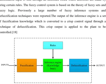
[image:19.595.119.525.204.524.2]Fuzzy Logic Controller has three successive blocks through which the control signal is generated in Figure 2.4.The first block fuzzification the input, this fuzzification input is sent through an inference block where decisions are made by firing certain rules. The fuzzy control system is based on the theory of fuzzy sets and fuzzy logic. Previously a large number of fuzzy inference systems and defuzzification techniques were reported.The output of the inference engine is a set of fuzzification knowledge which is converted to a crisp control signal through a technique of defuzzification. This crisp output is applied to the plant to be controlled.[18]
Figure 2.4: Block Fuzzy Logic Controller
The fuzzy control can overcome some shortcomings of traditional PID. The fuzzy controller is a language controller. The algorithm of fuzzy control can be obtained from experience and optimized from the operation, which has advantages such as powerful anti-interference, faster response and strong robust. But the fuzzy is a nonlinear control and the controlled object's output has the static error. The union of fuzzy control and traditional PID control can enhance various aspects of the control process in the air condition system.[17,11]
Rules
Fuzzification
Inference engine (Knowledge
base)
Defuzzification
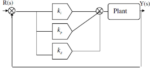
2.5 PID Controller
The most important and popular controller in industrial process is Proportional Integral Derivative (PID) because it easy to understand and easy to be used as a controller. But there are major problems that occur when using the PID controller which cause disturbance and environmental condition on the structural of the system. However when it compared to other controller, the PID are better and simple structure [7]. To the controlled object in air condition system, the traditional PID control can be applied, but it has some disadvantages such as inconvenient tuning parameters, faint anti-interference and large overshoot [17]. The traditional PID control method has the characteristics of simple construction, good stability, and mature theories. But the PID method excessively depends on the model parameters, and the robustness is poor [6].
From a mathematical viewpoint, the PID control works to push the error e(t) to zero, where
(2.1)
with T(t) being the measured temperature input and to being the set point temperature. The control voltage uc(t) takes the form:
(2.2) [image:20.595.126.443.574.718.2]
where , and are scale factors for the proportional, integral and differential terms respectively.
2.6 Fuzzy PID Controller
Each controller, either PID or Fuzzy has advantages and disadvantages. To improve the performance of this controller, the two controllers may be combined to gain advantages of both. PID works perfect in linear system while Fuzzy functions well for non linear system. The purpose of combining FLC and PID controller is to have a best result from the two relatively simple controllers, which might be similar to a complex controller. In realizing this idea, FLC is used to tune the PID gain. Self tuning can also improve the performance of PID controller. Therefore, a PID type Fuzzy controller is preferred in the non-linear process due to its simplicity, robustness and variable structure. The hybrid of fuzzy and PID controllers takes advances of the non-linear characteristics of the fuzzy controller and the accuracy near a set point which is guaranteed by classical PID controller. [8-17]
There are several combinations of hybrid fuzzy logic and PID existed. In the study of fuzzy-PID controller structure, there are five types of combination of fuzzy logic and PID that already have been used. They are Fuzzy PD+I, Fuzzy PI+D, Fuzzy PI+Fuzzy PD, Fuzzy P+ID and Fuzzy P+Fuzzy I +Fuzzy D. Each of them have their own advantages and disadvantages and also how to tune and setting.
2.6.1 Fuzzy PD control with parallel integral action (Fuzzy PD + I)
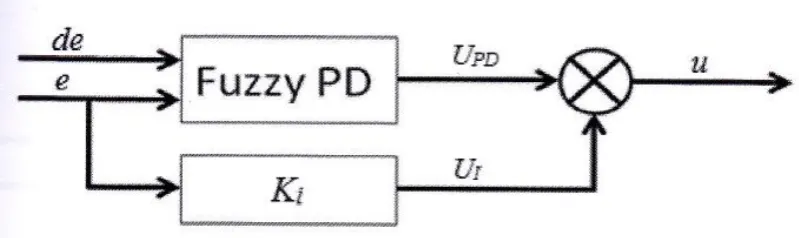
[image:21.595.118.518.608.727.2]According to [45], the structure of this approach can be achieved by placing a fuzzy PD controller in parallel with the conventional integral controller as shown in Figure 2.6.
From Figure 2.6, the control action is obtained with the sum of output from the fuzzy PD controller and the output from the conventional integral controller. de and e are derivative error and error input respectively. is the output of integral gain while is the output from hybrid fuzzy PD. u is the fuzzy PD+I combination output. The structure can be represented in a mathematical equation as:
(2.3)
where is integral gain that has to be determined.
The advantage of this approach is that the integral action can remove the system steady state error. However, this approach has poor transient response because of the integral gain, . To achieve a faster response, the integral gain should be large. But, if the gain is too high it will cause damping oscillation which will decrease the transient response. The value of integral gain must be determined properly.
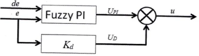
2.6.2 Fuzzy PI control with parallel derivative action (Fuzzy PI+D)
[image:22.595.146.489.581.678.2]According to [45], the structure of this approach can be achieved by placing a fuzzy PI controller in parallel with the conventional derivative controller as shown in Figure 2.7.
From Figure 2.7, the control action is obtained with the sum of output from the fuzzy PI controller and the output from the conventional derivative controller. de and e are derivative error and error input respectively. is the output of derivative gain while is the output from hybrid fuzzy PI. u is the fuzzy PI+D combination output. The structure can be represent in mathematical equation as:
(2.4)
where is derivative gain that has to be determined.
The advantage of this approach is that the derivative action can avoid the derivative kick and reduce the high frequency noise which can occur while using fuzzy PD+I controller. This approach can increase the transient response which can be in improvement for fuzzy PD+I controller. But if the derivative gain is too high, it can slow the steady state response which can decrease the performance of the whole controller. The value of derivative gain must be determined properly for better result.
For tuning the fuzzy PI+D controller, it is recommended to tune the fuzzy PI control first without using derivative gain , . Then keep input gains unchanged after adding derivative gain , .
2.6.3 Fuzzy PI control with parallel fuzzy PD control (Fuzzy PI + Fuzzy PD)
According to [45], the general type of this structure of fuzzy PID controller is shown in Figure 2.8. The control action is obtained with the sum of output from the fuzzy PI controller and the output from the fuzzy PD controller.
From Figure 2.8, the control action is obtained with the sum of output from the fuzzy PI controller and the fuzzy PD controller. de and e are derivative error and error input respectively. is the output from hybrid fuzzy PI while is the output from hybrid fuzzy PD. u is the fuzzy PI+ fuzzy PD combination output.
This type of structure can avoid the complexity of the rule-base and membership function design. The both fuzzy PI and fuzzy PD controllers can use the same membership function and the same rule base. Only the gain for the input and output signals have to be tuned properly. The final control action can be expressed as a sum of both control action as below:
(2.5)
For tuning the fuzzy PI + fuzzy PD controller, it is recommended to tune the fuzzy PI controller first without using the fuzzy PD controller. Then keep the gains for input signals unchanged after adding fuzzy PD control and adjust the gains for output signals to obtain an appropriate result. The simulation result using fuzzy PD + I, fuzzy PI+D and fuzzy PI + fuzzy PD controller compared to PID controller is shown in Figure 2.9.
where
1. Classical PID controller
2. Fuzzy PI + fuzzy PD controller 3. Fuzzy PI + D controller
4. Fuzzy PD + I controller
2.6.4 Fuzzy P control with parallel integral and derivative action (Fuzzy P+ID)
The general structure of this approach can be achieved by placing a fuzzy P controller in parallel with the conventional integral and derivative controllers as shown in Figure 2.10.
Figure 2.10: Fuzzy P controller with integral and derivative controller
From Figure 2.10, the control action is obtained with the sum of output from the fuzzy P controller and the output from the conventional integral controller and the output from the conventional derivative controller. de and e are derivative error and error input respectively. is the output of integral gain, is the output from hybrid fuzzy P and is the output of derivative gain while u is the fuzzy P + ID combination output. The structure can be represented in mathematical equation as below:
(2.6)
According to [46], this approach has the following features:
1. It is easy to design because it has only one parameter to be adjusted based on original PID controller.
2. The fuzzy P+ID controller keeps the simple structure of the PID controller. 3. The sufficient stability condition shows that the same stability remains
unchanged if the original PID controller structure is replaced by the fuzzy P + ID controller structure.
The idea of combining the fuzzy logic with PID controller using this type of structure is to use the integral and derivative controller as stabilizer while fuzzy P controller used to improve the control performance. The fuzzy P term improve overshoot and rise time response while integral term reduces steady state error and derivative term reduce overshoot and improve the combined controller process stability. For tuning the fuzzy P+ID controller, proportional , integral and derivative gain must be tune properly from the original PID structure. Then the proportional controller is replaced by fuzzy P.
2.6.5 Fuzzy P control with parallel Fuzzy I and Fuzzy D(FuzzyP + Fuzzy I+Fuzzy D)
The general structure of this approach can be achieved by placing a fuzzy P controller in parallel fuzzy I controller and fuzzy D controller as shown in Figure 2.11.
From Figure 2.11, the control action is obtained with the sum of output from the fuzzy P controller, the output from the fuzzy I controller and the output from the fuzzy D controller. de and e derivative error and error input respectively. is the output of the fuzzy P controller, is the output of the fuzzy I controller and is the output of the fuzzy D controller while u is the fuzzy P + fuzzy I + fuzzy D controller combination output. The structure can be represented in mathematical equation as below:
(2.7)
According to [47], the advantages of using this structure type are:
1. The structure is similar to original conventional PID controller which is placed parallel to each other.
2. The fuzzy P + fuzzy I + fuzzy D controller structure will increase the degree of freedom of the controller where user has more flexibility to achieve the desired response.
3. The fuzzy P + fuzzy I + fuzzy D controller can reduce overshoot and settling time.
4. This type of structure can avoid the complexity of the rule-base and membership function design where all fuzzy P, fuzzy I and fuzzy D controllers can use the same membership functions and the same rule base.
Each of the fuzzy parameter is tuned manually in suitable range value. Then the fuzzy logic controller will tune the PID controller gain automatically to get the best result. This operation is called self tuning PID controller gain by using fuzzy logic.
2.7 Intelligent Adaptive Controller
which the controller parameters are adjusted automatically to compensate for the changing process conditions or environment.
In many cases, it is necessary or useful to have a model of the system available online while the system is in operation. The model should then be based on observations up to the current time. The need for such an on-line model construction typically arises since a model is required in order to take some decision about system [47]. Adaptive control is an approach to controlling systems that adjusts over time in response to changing conditions and knowledge acquired by the controller. Rather than remaining static or attempting to cope with minor deviations, adaptive control actively responds to changes in the system to improve the control.
This approach is needed with dynamic systems in unstable environments, ranging from aircraft to medical robots. With adaptive control, the controller collects data about the environment of the system is operating in and uses this information to make adjustments to how the system is controlled. Examples of adaptive control can be seen in some vehicles with the ability to adjust automatic braking systems for wet and icy conditions. In these cases, the system responds to the conditions to improve accuracy, effectiveness, and efficiency to make driving safer and easier in a wide variety of settings.In recent years, Fuzzy Logic Control (FLC) [45] and Artificial Neural Network (ANN) [33], the branches of Artificial Intelligence (AI), have traced considerable attention as candidates for novel computational systems because of the variety of advantages that they offer over the conventional computational systems. [47] have proposed a model reference adaptive neurocontroller based on feed-forward neural network with momentum back-propagation learning algorithm. This approach is only utilized for nonlinear system. However, it needs a small number of tuning parameters requiring a few trails and error to be properly selected.
found that the system is remains steady in spite of the application of brusque parameters variations of the system.
[48] have designed ANFIS PID controller which is based on the Adaptive Neuro-Fuzzy Inference System to control the Steam Generators (SG) water level on the computer. They used the neural network which has ability of self-studying to calculate the fuzzy rule and membership function with back-propagation algorithm to overcome the awkward task of choosing membership function of fuzzy controller. They conclude that the ANFIS PID control effect is better than fuzzy controller or general cascade PI controller and they found that ANFIS needs empirical data to establish fuzzy rule and adjust membership function. So more empirical data needs to be obtained to achieve the better control effect.
CHAPTER 3
METHODOLOGY
3.1 Introduction
In this chapter, the methodology to develop the controller from including, doing the literature review, deriving the mathematical model of the plant and designing the controller is described. The plant mathematical model is used to represent the real application which was simulated using a program code in Matlab. The controller is based on Adaptive Fuzzy.
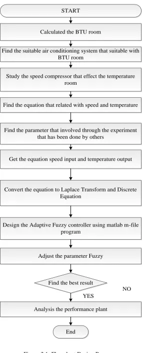
3.2 The process flow
Figure 3.1: Flowchart Design Process START
Calculated the BTU room
Find the suitable air conditioning system that suitable with BTU room
Study the speed compressor that effect the temperature room
Find the equation that related with speed and temperature
Find the parameter that involved through the experiment that has been done by others
Get the equation speed input and temperature output
Convert the equation to Laplace Transform and Discrete Equation
Design the Adaptive Fuzzy controller using matlab m-file program
Adjust the parameter Fuzzy
Find the best result
End
NO
In order to find the mathematical model of the plan, firstly the calculation of room BTU is taken into account. The heat from the room will affect the actual room temperature. To find the value of the BTU, the all aspect heat load must be considered. The heat load depends on a number of factors, by taking into account those that apply in your circumstances and adding them together a reasonably accurate measure of the total heat can be calculated. Factors include the floor area of the room, the size and position of windows, and whether they have blinds or shades, the number of room occupants, the heat generated by equipment and the heat generated by lighting.
Based on the BTU room value, the air conditioning system is selected. From the air conditioning system, the type of compressor will be known. The compressor that affects the temperature room equations is very complicated. The process of heat transfer starts from the compressor speed to evaporator coil and the condenser coil. The condenser coil then changes the output temperature. To find the relationship between speed compressor and output temperature, the evaporator and condenser are ignored. The parameters that are involved are obtained through the experiments that have been done by the others researches [44].
The controller is based on the adaptive fuzzy controller and is realized using Matlab programming and Simulink. The fuzzy block parameters are designed using the fuzzy.fis that is available in Matlab. The plant is controlled with adaptive fuzzy controller. To get the best performance, the parameters of adaptive fuzzy controller are adjusted. It is quite a challenging task to tune the parameters.
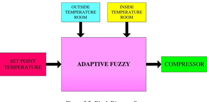
3.3 Control System Block Diagram
ADAPTIVE FUZZY COMPRESSOR
OUTSIDE TEMPERATURE
ROOM
INSIDE TEMPERATURE
ROOM
[image:33.595.115.520.67.266.2]SET POINT TEMPERATURE
Figure 3.2: Block Diagram System
As the speed of an induction motor is proportional to the frequency of the AC, the compressors runs at different speeds. A controller can then sample the current ambient air temperature and adjust the speed of the compressor appropriately. The output of fuzzy controller is the compressor speed that has 4 different modes that are off, low, medium and fast. The difference of the two temperatures readings by temperature sensors will be compared to the set point value in order to get the comfortable temperature for consumers. The set point temperature for this project is set to 20° C. The heat from the room is taken into account to measure the actual room temperature. The calculation of BTU room will be discussed in next section.
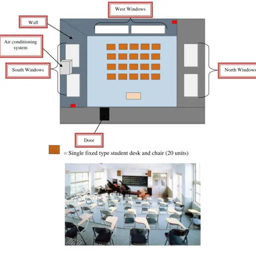
3.4 Calculation classroom BTU
= Single fixed type student desk and chair (20 units)
Figure 3.3: Classroom arrangement
3.4.1 Floor Area of Room
The amount of cooling required depends on the area of the room. To calculate the area in square meters:
Room Area BTU = Length (m) x Width (m) x 337 (3.1) 4m x 5m x 337 = 6740m²
Air conditioning system
North Windows West Windows
Door Wall
REFERENCES
[1]. Marc A. Rosen (2009). Development of an Enhanced Ceiling Fan:An Engineering Design Case Study Highlighting Health, Safety and the
Environment. Faculty of Engineering and Applied Science University of Ontario Institute of Technology: Ph.D., P.Eng.
[2]. Zamri Noranai, Dayang Siti Zainab Abang Bujang, Rosli Asmawi, Hamidon Salleh, and Mohammad Zainal Md Yusof (2012) , Development Of Cooling Load Demand Program For Building In Malaysia. Faculty of Mechanical and Manufacturing Engineering, Universiti Tun Hussein Onn Malaysia.
[3]. Principles of Home Inspection: Air Conditioning and Heat Pumps. Copyright 2012.Retrieved on 2012,from http://www.recampus.com/documents/book02c 01.pdf
[4]. Sousa, J. M., Babuska, R.and Verbruggen, H. Internal model control with a fuzzy model: application to an air-conditioning system. Fuzzy Systems, 1997., Proceedings of the Sixth IEEE International Conference on. 1997. 207-212 vol.1
[5]. Jia, Lei , Lv, Hongli ,Wenjian, Cai. Model Predictive Control Based on Fuzzy Linearizatio Technique For HVAC Systems Temperature Control. Industrial Electronics and Applications, 2006 1ST IEEE Conference on.2006. pp.1-5
[6]. Wenju, Yuan, A Self-Tuning Fuzzy PI Temperature Controller. New Trends in Information and Service Science, 2009. NISS '09. International Conference
on. 2009. pp. 336-338
[9]. Jiang, Jing,Zhang and Xuesong. Temperature control system of air-conditioning based on the fuzzy theory. Mechatronics and Automation (ICMA), 2011 International Conference on.pp. 387-391.
[10]. Jiang and Wei. Research on the temperature control system based on fuzzy self-tuning PID. Computer Design and Applications (ICCDA), 2010 International Conference on.pp. V3-13-V3-15.
[11]. Jiangjiang, Wang,Dawei, An Chengzhi and Lou. (2006). Application of Fuzzy-PID Controller in Heating Ventilating and Air-Conditioning System. Mechatronics and Automation, Proceedings of the 2006 IEEE International
Conference on.pp. 2217-2222.
[12]. Jianping, Xie,Xiaohong, Kong,Xiaoyan, Huang,QingJie and Yang. Application of self-adaptive fuzzy PI control in the air-conditioning system. Control and Decision Conference (CCDC), 2010 Chinese.pp. 2999-3002. [13]. Lijuan, Xing,Shizhong and Yang. Fuzzy-PID Controller with Variable
Integral Parameter for Temperature Control in Variable Air Volume Air Conditioning Systems. Electrical and Control Engineering (ICECE), 2010 International Conference on.pp. 1050-1053.
[14]. Manish, G.Peng-Yung and Woo.( 1996). Efficiency of fuzzy and adaptive fuzzy controllers relative to PID controller in temperature control. Intelligent Control, 1996., Proceedings of the 1996 IEEE International Symposium
on.pp. 55-60.
[15]. Mingfang, Du, Zhaoli, Zhang ,Yanxia and Liu.( 2009). A Research on Expert Fuzzy-PID Fusion Controller Algorithm in VAV Central Air Conditioning System. Intelligent Information Technology Application, 2009. IITA 2009. Third International Symposium on.pp. 194-198.
[16]. Wang, Li-li,Yang, Jun,Zhou and Xiao-guang.(2009). Modeling and Control of Temperature in VAV Air Conditioning System. Computational Intelligence and Software Engineering, 2009. CiSE 2009. International
Conference on.pp. 1-4.
[18]. Lee, C.-C.Fuzzy logic in control systems: fuzzy logic controller-parts 1 and 2.IEEE Transactions on Systems, Man, and Cybernetics, Vol. 20, No. 2,pp 404-435.
[19]. Michigan (2012).Publish with MATLAB -7.14.copyright 2012. Retrieved on 2012,fromhttp://ctms.engin.umich.edu/CTMS/index.php?FuzzyLogicToolbox .pdf.
[20]. Ahmad Parvaresh, Seyed Mohammad Ali Mohammadi and Ali Parvaresh. A New Mathematical Dynamic Model For HVAC System Components Based On Matlab/Simulink. International Journal of Innovative Technology and Exploring Engineering (IJITEE).pp. 2278-3075, Volume-1, Issue-2, July 2012.
[21]. Zamri Noranai, Dayang Siti Zainab Abang Bujang, Rosli Asmawi, Hamidon Salleh, Mohammad Zainal Md Yusof. Development of Cooling Load Demand Program for Building in Malaysia. World Academy of Science, Engineering and Technology 63 2012.
[22]. R. Babuska, J.A. Roubos and H.B. Verbruggen. Identication of MIMO systems by input output TS fuzzy models. Delft University of Technology, Department of Electrical Engineering, Control Laboratory Mekelweg 4 The Netherlands.
[23]. Takanori Yamazaki1, Yuji Yamakawa2,Kazuyuki Kamimura3 and Shigeru Kurosu4. Air-Conditioning Pid Control System With Adjustable Reset To Offset Thermal Loads Upsets. 1Oyama National College of Technology, 2Univ. of Tokyo, 3National Institute for Environmental Studies,4Research Inst. “Crotech”,Japan.
[24]. M. Abbas, M. Saleem Khan, Fareeha Zafar. Autonomous Room Air Cooler Using Fuzzy Logic Control System. International Journal of Scientific & Engineering Research Volume 2, Issue 5, May-2011.pp. 2229-5518.
[25]. Amiya Patanaik.Fuzzy Logic Control of Air Conditioners.Roll number 05EG1008. Department of Electrical Engineering Indian Institute of Technology, Kharagpur India.
Engineering, Henan Institute of Science & Technology, Xinxiang 453003, China.
[27]. Brandon S. Frink (2005) Modeling And Construction Of A Computer Controlled AirconditioningSystem.Retrieved03/15/2010.fromhttp://www.scribd.com/doc/28 400647/Modeling-Refrigeration-System-With-Simulink-Frink-2007.
[28]. Ganderton. (2012). How you calculate the size of an air conditioner for a room? Retrieved on Copyright © 2013 Answers Corporation. From http://wiki.answers.com/Q/How_you_calculate_the_size_of_an_air_conditio ner_for_a_room.
[29]. Michigan (2012).Publish with MATLAB -7.14.copyright 2012. Retrieved on 2012,fromhttp://www.mathworks.com/help/physmod/powersys/ug/simulating -an-ac- motor-drive.html
[30]. Cton ,Dean Scott 119 Grassy Lake Vincenttown , New Jersey 08088 (US). System and method for fan speed control. 0419214 A2.
[31]. Kungwalrut,P.,Thumma,M.,Tipsuwanporn,V.,Numsomran,A.and
Boonsrimuang, P. Design MRAC PID control for fan and plate process. SICE Annual Conference (SICE), 2011 Proceedings of. pp.2944-2948.
[32]. Michigan (2012).Publish with MATLAB -7.14.copyright 2012. Retrieved on 2012,fromhttp://ctms.engin.umich.edu/CTMS/index.php?example=MotorSpe ed§ion=ControlPID .
[33]. Montiel, O.,Sepulveda, R.,Melin, P.,Castillo, O.,Porta, M. A.and Meza, I. M. Performance of a Simple Tuned Fuzzy Controller and a PID Controller on a DC Motor. Foundations of Computational Intelligence, 2007. FOCI 2007. IEEE Symposium on.pp. 531-537.
[34]. Meshram, P. M.and Kanojiya, R. G.(2012). Tuning of PID controller using Ziegler-Nichols method for speed control of DC motor. Advances in Engineering, Science and Management (ICAESM), 2012 International
Conference on.pp. 117-122.
[35]. Montiel, O.,Sepulveda, R.,Melin, P.,Castillo, O.,Porta, M. A.and Meza, I. M. (2007). Performance of a Simple Tuned Fuzzy Controller and a PID Controller on a DC Motor. Foundations of Computational Intelligence, 2007. FOCI 2007. IEEE Symposium on.pp. 531-537.
Conference and Exposition, 2005. APEC 2005. Twentieth Annual IEEE.pp. 148-151 Vol. 1
[37]. Ibrahim, Dogan (2002). “Microcontroller Based Temperature Monitoring and Control”. Elsevier Science & Technology Books.pp.14-35
[38]. Chen, G., & Pham, T. T. (2001). Measurering system Boca Raton, FL: CRC Press.pp.25-30
[39]. Jiaoyue, Liu,Lin, Ma Juqing and Yang.(2011). Methods and techniques of temperature measurement. Electrical and Control Engineering (ICECE), 2011 International Conference on.pp. 5332-5334.
[40]. Kadir, K. M.,Forhad, M. S.,Fadlullah, M. M.,Quader, N.,Al-Arif, M. M. R.and Dhali, M. A.(2011). Energy saving by automatic control of power in simple home appliances. Communication Software and Networks (ICCSN), 2011 IEEE 3rd International Conference on pp. 311-315
[41]. Jingjing, Du,Shuiying, Zhang,Xuebo, Jin and Guohong, Yan.(2011). The Design of Ultrasonic Distance Measurement System Based of SOPC. Intelligent Human-Machine Systems and Cybernetics (IHMSC), 2011
International Conference on.pp. 166-168
[42]. Publish with City Engineering Limited. Retrieved on 2012,from http://cityeng.co.uk/BTUcalculator.php.
[43]. M.Abbas, M.Saleem Khan and Fareeha Zafar.(2011).Autonomous Room Air Cooler Using Fuzzy Logic Control System.International Journal of Scientific & Engineering Research Volume2, Issue 5, May-2011.pp.2229-5518
[44]. J. H. Darr and R. R. Crawford.(1992). Modeling of an Automotive Air Conditioning Compressor Based on Experimental Data. Air Conditioning and Refrigeration Center University of Illinois Mechanical & Industrial Engineering Dept.1206 West Green Street Urbana. pp333-3115
[45]. Michail Petrov, Ivan Ganchev, Krum Kutryanski. A study on the Fuzzy PID controller. Control System Department, Technical University.
Conference on Control, Automation and Systems 2010 Oct. pp. 27-30, 2010 in KINTEX, Gyeonggi-do, Korea.
![Figure 2.1: Schematic of Air Conditioning System [3]](https://thumb-us.123doks.com/thumbv2/123dok_us/8773079.899923/15.595.118.523.208.512/figure-schematic-air-conditioning.webp)
![Figure 2.2: The process of cooling system [27]](https://thumb-us.123doks.com/thumbv2/123dok_us/8773079.899923/17.595.122.522.440.661/figure-process-cooling.webp)