International Journal of Emerging Technology and Advanced Engineering
Website: www.ijetae.com (ISSN 2250-2459,ISO 9001:2008 Certified Journal, Volume 3, Issue 3, March 2013)
745
Problems and Simulation of grid connected Small power plants
Mon Prakash Upadhyay
1, Subhash Yadav
21Assistant Professor, Electrical Engineering Department, Invertis University Bareilly-243123, India 2
Assistant Professor, Electrical Engineering Department, JSS Academy of Technical education Noida, India
Abstract—Electricity grid interconnections have played a key role in the history of electric power systems. The greatest benefits of interconnection are usually derived from synchronous AC operation, but this can also entail greater reliability risks. An alternative energy supply to assist the main power stations in future is expected from renewable energy sources based on distributed generation like Small hydropower power plant (SHP). SHP capacity has experienced tremendous growth in the past decade due to its environmental benefits, technological advances and government incentives. In this paper describes the grid interconnection elements, problems associated with grid interconnection and SHP station operation during grid connected mode.
Keywords— Grid-connection, Small hydro plants, mat-lab simulation, fault.
I. INTRODUCTION
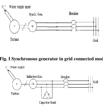
[image:1.612.78.254.453.638.2]In case of grid connected mode, governor is used for maintaining the balance between mechanical power & electrical power. Fig. I and II show the connection schemes of SHPs in grid connected mode
[image:1.612.82.250.461.528.2]Fig. I Synchronous generator in grid connected mode
Fig. II Induction generator in grid connected mode
In the case of induction generator, requirement of capacitor bank is optional. The grid-connected SHPs can further be classified into following two categories:
A. Power plants with local load:
These power plants will regularly operate in parallel with connected grid, but supply the requirements of localized industrial or other facility. The power plant and load together may be considered of electrical energy either as a net importer of electrical energy to grid or as a net exporter of electrical energy from grid.
B. Power plants with-Out local load:
These power plants are typically connected to grid through a dedicated line. Typically, there will be no other customer load between the grid substation and power plant. The generators of these power plants will always operate in parallel with the grid.
II. REQUIREMENTR OF GRID INTERCONNECTION OF THE
SHP PLANTS
Grid system consists of transmission and distribution system, transformer, protection equipment etc. Different regions have different amounts of hydro potentials for power generation as well as different demand patterns. Some areas may have deficient hydro capacity to serve the load while other areas may have significant amounts of spare hydro capacity after serving the load. In this condition enhanced interconnections and trade within and among different regions can significantly improve the load factor, lower the overall costs of power production and diversify sources of power supply. Stronger grids may also open up new avenues of competition among private SHP owners further limiting power costs to industry and consumers. Following are the main requirements of grid interconnection of SHP plants are: To ensure the safety of the SHP plants operating in parallel with Grid to facilitate the safety of large industrial consumer, and general public. To maintain a high standard of power quality to coordinate of maintenance schedules.
III. GRID INTERCONNECTION PROBLEMS
International Journal of Emerging Technology and Advanced Engineering
Website: www.ijetae.com (ISSN 2250-2459,ISO 9001:2008 Certified Journal, Volume 3, Issue 3, March 2013)
746 Thermal limits, stability limits, and voltage regulation are the main constraints on transmission line operation. Other transmission problems include loop and parallel path flows, and available transfer capacity. System-wide problems include frequency regulation, power quality, the coordination of planning and operations, political and institutional cooperation. There are following points to be addressed adequately during grid interconnection.
A. Thermal limits:
The capacity of transmission lines, transformers, and other equipment is determined by temperature limits. If these limits are exceeded, the equipment can be damaged or destroyed. Equipment ratings have traditionally been conservative, and operators have stayed well below the rated limits, but increased power trading in liberalized markets has created pressure for higher utilization. Instead of a single thermal limit, dynamic ratings are now often used. For example, transmission lines can carry more current when heat is effectively dissipated, and thus will have a higher rating on cold, windy days without direct sunlight. When transmission lines heat up, the metal expands and the line sags. If the sag becomes too great, lines can come into contact with surrounding objects, causing a fault. Excess sag can also cause the metal to lose tensile strength due to annealing, after which it will not shrink back to its original length. Important transmission lines are often monitored by a device called a "sago meter", which measures the amount of sag, making system opera-tors aware of dangerous sag conditions. Thermal limits of a transmission line, distribution line are not a function of line length. Thus for a given line design, a line 1 km long and one 500 km long typically have the same thermal limit. Thermal limits usually determine the maximum power flow for lines less than 50 miles in length.
B. Stability limits:
The stability limit of a transmission line is the maximum amount of power that can be transmitted for which the system will remain synchronized if a disturbance occurs. The power flow through a transmission line is governed by the following relation:
P = Vr× Vs × sinδ / X
All other factors being equal, the power transmitted from the sending side to the receiving side increases as the difference in power angle between the two points, called δ (delta), approaches towards 90°, and decreases as it approaches towards 0°. However, the feedback mechanism that keeps generators in synchronism and returns them to synchronous operation if they are disturbed becomes more tenuous as δ approaches 90°.
The stability limit represents the value of the power angle that allows the highest power transfer while maintaining stability; a typical maximum value of is δ around 45°.In general, stability limits are more important than thermal limits for long transmission lines, while thermal limits are more important for shorter lines.
C. Frequency variation:
The frequency deviation of a power system shall be limited to a specified modest range at the distribution level. For system operating at a nominal frequency of 50 Hz, the allowed frequency deviations are in the range of 48.5 Hz to 51.5 Hz i.e ± 3%. Impact of frequency variation is that at low frequencies the VAR output of power factor correction capacitors reduces thereby affecting the power factor. Also operation at low frequencies increases the flux in transformer thus pushing them near saturation and these results in increased VAR consumption and increased losses. A change in grid frequency beyond the safe limit can damage the equipment like generation, Transmission and various grid equipment. It could degrade the quality of the power being delivered to end users. It could also result in the collapse of the power systems itself (by triggering protective system action).
D. Voltage regulation:
Voltage regulation describes the process and equipment to maintain voltage within acceptable limits. The primary objective of grid voltage regulation is to provide each customer connected to the grid with voltage that confirms to the design limitations of the customer's utilization equipment. Almost all utilization equipment is designed for use at a definite terminal voltage: the nameplate voltage rating. The voltage drops from the source to the utilization devices make it economically impractical to provide all customers with a constant voltage that corresponds to the nameplate voltage of their utilization devices. Thus, a compromise is necessary between the allowable deviation from utilization equipment nameplate voltage supplied by the power system and the deviation above and below the nameplate voltage at which satisfactory equipment performance can be obtained [1].
E. Synchronization:
International Journal of Emerging Technology and Advanced Engineering
Website: www.ijetae.com (ISSN 2250-2459,ISO 9001:2008 Certified Journal, Volume 3, Issue 3, March 2013)
747 For three-phase applications, SHP phase rotation is typically checked at the time of SHP installation, with the phases being connected to the switches such that the phase rotation will always be correct. Synchronization is only a major concern for synchronous generators which is generating a voltage prior to synchronize action with the grid.
F. Power quality:
Power quality phenomena include all possible situations in which the waveforms of the supply voltage or load current deviate from the sinusoidal waveforms at rated frequency with amplitude corresponding to the rated rms value of all three phases of a three-phase systems. The wide range of power quality disturbances cover sudden and short-duration deviation e.g. impulsive and oscillatory transients, voltage dips (or sags), short interruption, as well as study-state deviation such as harmonics and flicker.
Harmonic in power systems have received increased attention in recent years with the widespread application of advanced solid state power switching device in a multiple of power electronic applications. The ac power systems has a substantial number of large harmonic generating device i.e. adjustable speed drives for motor control and switch mode power supplies used in a variety of office equipment such as PCs fax machine etc. These devices draw non sinusoidal load currents consisting primarily of lower order 5th, 7th, 11th and 13th harmonics that distort the system power quality.
G. Grid fault:
Grid has detected a fault and de-energizes circuit any other source on that circuit needs to also stop energizing it. Maximum faults are limited by restricting substation transformer size, impedance or both installing bus or circuit reactors or inserting reactance or resistance in the transformer neutral. Minimum fault magnitude is largely dependent on fault resistance, which cannot be controlled. These low-magnitude faults are the most dangerous and difficult to detect. All detectable faults are cleared to minimize equipment damage, provide for public safety, and maintain overall reliability and power quality for all customers. Clearing times for short circuits on grid vary widely and depend on the magnitude and type of protective equipment installed. In general, on most circuits, large current faults will be cleared in 0.1 s or less. Low-current faults frequently require clearing times of 5 s to 10 s or longer. Some very low level but potentially dangerous ground faults may not be cleared except by manual disconnection of the circuit. A supply systems is typically supplied through a circuit breaker or recloser located at the supply substation.
It is divided into zones by fuses, recloses, or automatic sectionalizing devices that operate after counting current interruptions within a predefined time period. Most faults on the supply system are temporary in nature. That is, most faults are due to tree encroachment in an overhead distribution line, lightning, or other causes such that the source of the fault is gone after the initial operation of the protective devices. Therefore, automatic reclosing is usually employed on substation breakers or reclosers and on line reclosers, so the duration of an outage for most faults is limited to only a few seconds.
H. Available transmission capacity (ATC):
An important measure of transmission capacity is transmission transfer capability (TTC), which is the maximum power flow that a line can accommodate at any given time and still be able to survive the loss of a major generator or transmission link elsewhere in the system. Available transmission capacity (ATC) is the TTC of a line minus the amount of capacity already committed to other uses on that line. ATC is thus the measure of how much power can be safely transmitted over a transmission line at a given time while ensuring overall system reliability.
I. Surge Voltage:
Transient surge voltages that occur in ac power circuits can be the cause of operational upset or product failure in industrial and residential systems and equipment. These problems have received increased attention in recent years because of the widespread application of complex semiconductor devices that are more sensitive to voltage surges than vacuum tubes, relays, and earlier generations of semiconductor devices. Logical and economical design of circuits to protect vulnerable electronic systems from upset or failure requires knowledge or estimates of the following: [1]
IV. RECOMMENDATION
International Journal of Emerging Technology and Advanced Engineering
Website: www.ijetae.com (ISSN 2250-2459,ISO 9001:2008 Certified Journal, Volume 3, Issue 3, March 2013)
748 The sync-check relays may also serve as signal devices for automatically closing the breaker at the PCC. Highly accurate and reliable automatic synchronization relays and electronic transducer combination packages are available with adjustable ranges to monitor and control the synchronism, frequency, phase or power factor and the voltage levels of the distributed generator. All governors are proportional control (p type) for its controlled speed/frequency inputs. These p type controls are not able to cancel frequency error. Because of that, a small grid frequency error is still present after the action of governors. This kind of frequency control action is referenced as frequency primary control (FPC).
V. SIMULATION OF SHPPLANT IN GRID CONNECTED
MODE
In this case, the SHP plant consists hydro-turbine coupled with synchronous generator and is connected to grid as shown in Fig.III. For simulating this systems, same parameters of synchronous machine, excitation systems, turbine and governor have been used as given in Table 1 In this case, first SHP plant is started at no load condition, then it is connected with grid at t= 0.01 s.
Fig III. Model of SHP plant in grid connected mode
TABLE 1
VALUES OF TRANSFORMER PARAMETERS FOR SIMULATION PURPOSE
Parameters Values
Nominal power, P 450 kVA
Frequency 50 Hz
Primary winding voltage, V1 415 V Primary winding resistance, R1 0.002 pu Primary winding inductance, L1 0.08 pu Secondary winding voltage, V2 11 kV Secondary winding resistance, R2 0.002 pu Secondary winding inductance, L2 0.08 pu Magnetization resistance, Rm 500 pu Magnetization reactance, Lm 500 pu
For this case, Rotor speed is shown in fig. IV. Rotor speed starts from 0.94 pu and oscillates due to inertia of machine for 1 s after that it attains a steady state value of 1.0 pu. Excitation voltage starts with very less value and raises upto 1.4 Pu after 15sec., it comes to a constant value of 1.09 pu. The simulated graph is shown in fig. IV initially very high stator current is observed followed by closing of circuit breaker at 0.01 s and after 0.5 s, it comes to steady state value. Three phase sinusoidal stator currents waveforms are shown in fig.V. Three phase sinusoidal stator voltages waveforms are shown in fig. VI. On grid side 100 kW load is connected at voltage level 11 kV. The load voltages vs time waveforms on 100 kW load sides. Three phase sinusoidal load currents vs time waveforms on 100 kW load sides.
[image:4.612.342.539.293.699.2]Fig .IV Waveform of Rotor speed vs Time
Fig.V. Waveform of excitation voltage vs Time
[image:4.612.65.265.398.548.2] [image:4.612.43.302.595.720.2]International Journal of Emerging Technology and Advanced Engineering
Website: www.ijetae.com (ISSN 2250-2459,ISO 9001:2008 Certified Journal, Volume 3, Issue 3, March 2013)
749 Fig.VII. Waveform of transient stator currents vs time
In this case, model is run for 15 sec to achieve steady state condition. Closing time of circuit breaker is taken as 0.01 sec. The analysis of stator current waveform shows that during the switching action of circuit breaker for connecting the SHP to grid and starting of synchronous generator, transient current appears in all the three phases as shown in Fig. VII.
VI. CONCLUSION
Small hydro power is a renewable, non- polluting and environmental friendly source of energy. It is perhaps the oldest renewable energy technique known to be the mankind for mechanical energy conversion as well as electricity generation. Small and mini hydel projects have the potential to provide energy in remote and hilly area. This paper presents detail description of problems associate with grid-interconnection of SHPs. The consideration of these problems is very important for safe and healthy operation of SHPs connected with grid.
REFERENCES
[1] IEEE standard 1547, “IEEE Standard for interconnecting Distributed Resources with Electric Power Systems”, December 2008.
[2] CEB guide for grid connection of embedded generator 2000. [3] IEEE standard 421.5, “Recommendation practice for Excitation