A requirements engineering framework
for integrated systems development for the
construction industry
Arayici, Y, Ahmed, V and Aouad, GF
Title
A requirements engineering framework for integrated systems
development for the construction industry
Authors
Arayici, Y, Ahmed, V and Aouad, GF
Type
Article
URL
This version is available at: http://usir.salford.ac.uk/551/
Published Date
2006
USIR is a digital collection of the research output of the University of Salford. Where copyright
permits, full text material held in the repository is made freely available online and can be read,
downloaded and copied for noncommercial private study or research purposes. Please check the
manuscript for any further copyright restrictions.
A REQUIREMENTS ENGINEERING FRAMEWORK FOR
INTEGRATED SYSTEMS DEVELOPMENT FOR THE
CONSTRUCTION INDUSTRY
SUBMITTED: March 2005 REVISED: October 2005
PUBLISHED: March 2006 at http://itcon.org/2006/3/ EDITOR: C. Anumba
Yusuf Arayici, Dr.
School of Construction and Property Management, University of Salford, Greater Manchester, UK email: [email protected]
Vian Ahmed, Dr.
School of Construction and Property Management, University of Salford, Greater Manchester, UK email: [email protected]
Ghassan Aouad, Prof.
School of Construction and Property Management, University of Salford, Greater Manchester, UK email: [email protected]
SUMMARY: Computer Integrated Construction (CIC) systems are computer environments through which collaborative working can be undertaken. Although many CIC systems have been developed to demonstrate the communication and collaboration within the construction projects, the uptake of CICs by the industry is still inadequate. This is mainly due to the fact that research methodologies of the CIC development projects are incomplete to bridge the technology transfer gap. Therefore, defining comprehensive methodologies for the development of these systems and their effective implementation on real construction projects is vital. Requirements Engineering (RE) can contribute to the effective uptake of these systems because it drives the systems development for the targeted audience. This paper proposes a requirements engineering approach for industry driven CIC systems development. While some CIC systems are investigated to build a broad and deep contextual knowledge in the area, the EU funded research project, DIVERCITY (Distributed Virtual Workspace for Enhancing Communication within the Construction Industry), is analysed as the main case study project because its requirements engineering approach has the potential to determine a framework for the adaptation of requirements engineering in order to contribute towards the uptake of CIC systems.
KEYWORDS: DIVERCITY, requirements engineering, computer integrated construction, prototyping, use case modelling, construction industry.
1.
INTRODUCTION
The integration of project information throughout the whole life-cycle of the project is facilitated through a computer environment, so called Computer Integrated Construction (CIC). Some of the features of these systems include;
• Emphasis on collaborative work for the construction stakeholders in order to overcome the fragmented nature of construction projects.
• New data exchange standards, such as IFC, for information exchange between the stakeholders. • New construction processes, which eliminate non-value adding activities.
• Provision of shared access to project information via integration over a central database or a communication layer to prevent duplication of information among stakeholders.
• Inclusion of VR (Virtual Reality) functions and 4D simulations at the design stage for build ability.
subject of research since the early 1990s, the uptake of this technology has been slow due to the development of these systems and their effective implementation (Alshawi & Faraj, 2000), (Aouad and Wafai, 2002).
There are a number of examples for the CIC systems that have been developed as prototypes to demonstrate time and cost savings throughout the lifecycle of construction projects. Some of these examples are ATLAS
(Greening and Edwards 1995), OSCON (Aouad et al 1997), SPACE (Alshawi et al, 1996), WISPER (Faraj et al, 2000), GALLICON (Sun & Aouad et al, 2000), VBE (Bazjanac, 2004), DIVERCITY (Arayici & Aouad, 2004), FIDE (Molina & Martinez, 2004), MOBIKO (Steinmann, 2004), PAMPER (Szigeti & Davis, 2003), BLIS (Laiserin, 2003) and many others.
Although the main focus of the earlier projects was data standards and common information models, through which heterogeneous computer systems could exchange project information, there was little attention and consideration to the user requirements capture and subsequent implementation of the prototypes (Tanyer, 2003), (Arayici, 2004).
It is claimed that the development of human centred, adaptive systems through industry-wide information sharing is crucial (Lee et al, 2003) (Aouad & Wafai, 2002). Furthermore, it is necessary to identify development techniques and methodologies that would lead to the user-centred, adaptive software systems in close
collaboration with the construction stakeholders. Besides, people from industry have stressed that construction IT researchers should align with the practitioners when developing and proposing IT solutions to the industry. Due to the identified gap between the research community and practitioners, there is still lack of communication and shared understanding incurred amongst them (Arayici, 2004).
To address this issue, the discipline of requirements engineering becomes vital for the CIC development. This discipline can influence not only the attributes of the systems but also how well it is targeted to user needs, the accuracy of the design and specification, the ultimate cost and quality of the final product (Cysneiros, 2002). The main focus of this paper is to demonstrate an understanding of requirements engineering to facilitate human centred, adaptive software systems development with close collaboration with the construction stakeholders. The DIVERCITY (Distributed Virtual Workspace for Enhancing Communication within the Construction Industry) project is a CIC system that has been developed by European project consortium in collaboration with industry and forms a good example of industry-oriented CIC system development. The success of this system is demonstrated through the adaptation of a requirements engineering approach. Therefore, this paper will introduce the DIVERCITY project as a case study that builds on the contextual knowledge of requirements engineering. The paper adopts a structured approach to analyse strengths and weaknesses of DIVERCITY’s approach and develops and a framework for adopting requirements engineering process in the CIC systems developments.
2.
REQUIREMENTS ENGINEERING
Requirements engineering is concerned with the goals, desired properties and constraints of complex systems that involve software systems, organisations and people. It also covers how requirements relate to business processes, soft issues, work redesign, system and software architecture and testing. This process is regarded as one of the most important aspects of building an information system because it is during this process that it is decided what is to be built (Lundh & Sandberg, 2002, Carr, 2000).
Keil (et al, 1998), Carr (2000), Nikula & Sajaneimi (2003), CHAOS (1995, 2000) also addressed the requirements engineering related risk factors that can cause project failure and lack of implementation. The combined set of RE related risks factors are; misunderstanding and misinterpretation of the requirements, lack of adequate user involvement, failure to manage end user expectations, changing scope and objections, lack of frozen requirements, conflict between user departments, incomplete and inconsistent requirements and specifications and ambiguous and vague requirements.
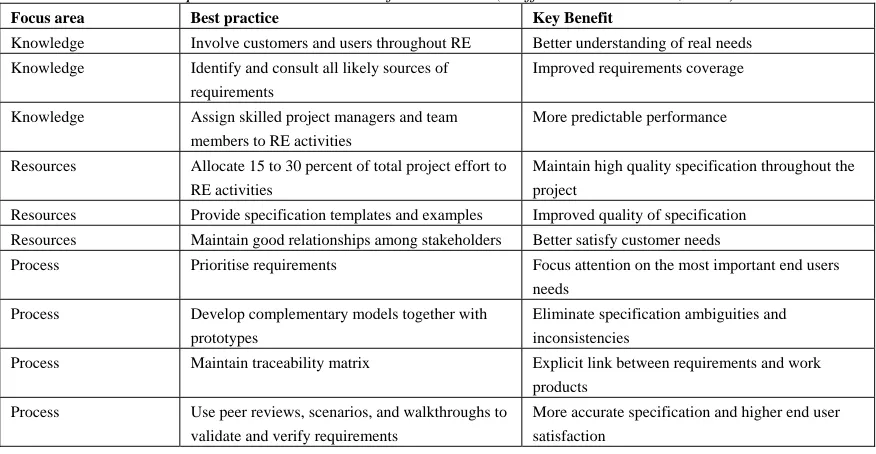
TABLE 1: The best RE practices in most successful RE teams (Hoffmann and Lehner, 2001)
Focus area Best practice Key Benefit
Knowledge Involve customers and users throughout RE Better understanding of real needs
Knowledge Identify and consult all likely sources of requirements
Improved requirements coverage
Knowledge Assign skilled project managers and team members to RE activities
More predictable performance
Resources Allocate 15 to 30 percent of total project effort to RE activities
Maintain high quality specification throughout the project
Resources Provide specification templates and examples Improved quality of specification
Resources Maintain good relationships among stakeholders Better satisfy customer needs
Process Prioritise requirements Focus attention on the most important end users needs
Process Develop complementary models together with prototypes
Eliminate specification ambiguities and inconsistencies
Process Maintain traceability matrix Explicit link between requirements and work products
Process Use peer reviews, scenarios, and walkthroughs to validate and verify requirements
More accurate specification and higher end user satisfaction
The process of requirements engineering needs business strategy in order to focus its activities, such as selecting information sources, prioritise requirements and screen ideas and concepts. Business strategy needs requirements engineering to gather detailed information about evolving industrial and technological environments, which are interdependent, whereby one cannot function effectively without the other (Nikula & Sajaneimi, 2003).
Elicitation, analysis and validation and management are at the heart of the requirements engineering process (Sommerville, 2000). The determination of what is to be achieved and what is required to accomplish the objectives are key aspects of software development. A careful process of study, understanding and analysis of requirements is necessary to deal with the complexities of the requirements elicitation. A validation procedure is essential to make sure if the right requirements are elicited and these requirements are met by the built system to fulfil the objectives. Lastly, requirements management is the process of managing requirements during the system development (Lundh 2002).
2.1 Requirements Engineering for CICs
CIC is an important solution for the integration of the processes through the construction supply chain. Yet, the developments of these systems have not reached at their ultimate effectiveness. This is mainly due to the lack of communication between the system developers and the industrialists. Arayici (2004) highlighted that the main goal of the CIC projects has been gradually diverting from demonstrating the possibility of the CIC concept to the practical adaptation, and the implementation of CIC in the construction industry. Arayici (2004) also argued that although there is some awareness of requirements engineering within the CIC community, it is ad hoc in its implementation. That is to say, there is no standard approach of requirements engineering in these CIC
developments and they inconsistently vary from one to another. Therefore, to bridge the gap between the system developers and industrialists, the role of requirements engineering as a discipline becomes vital.
Further research findings showed that requirements engineering is: necessary for verification and validation of the systems and facilitate the exploitation strategy; facilitator for close collaboration and communication with the construction stakeholders; a controllable parameter for the implementation of the system whereas there are some uncontrollable parameters such as cultural issues, legal issues, contractual issues, process and educational issues (Arayici, 2004).
In the next section, the DIVERCITY project as a CIC system is introduced. Since DIVERCITY’s requirements engineering approach had the potential to provide opportunities for research to determine the appropriate techniques for requirements engineering for the CIC community, the requirements methodology of DIVERCITY is examined in detail in order to identify the gaps, opportunities and new directions in the CIC development.
3.
THE DIVERCITY PROJECT
DIVERCITY is an abbreviation for a Distributed Virtual Workspace for Enhancing Communication within the Construction Industry (DIVERCITY Handbook 2003). It was funded by the EU commission in order to create:
• A client-briefing workspace that allows interaction and communication of design ideas between the client and the architect;
• An interactive design review workspace which allows multi-disciplinary design reviews involving different stakeholders of a construction project;
• A virtual construction workspace that allows the user to assess the constructability of a building, and plan and layout of the construction site;
• A software framework for integrating the above three workspaces and sharing them over networks to support collaboration between geographically distributed project team members;
The DIVERCITY system composed of six applications, namely: (i) client briefing; (ii) thermal simulation; (iii) acoustics simulation; (iv) lighting simulation; (v) 4D scheduling; and (vi) site planning. Three further
applications, which are transparent to end users support collaboration activities and provide mathematical algorithms for the simulation calculations. The functionality of this workspace is explained in detail in the DIVERCITY Handbook (2003), (Arayici & Aouad, 2004).
The following section explains the DIVERCITY’s approach to capturing the construction industry’s requirement.
3.1. DIVERCITY’s Requirements Engineering Approach
DIVERCITY is a large-scale, highly innovative and interactive workspace. DIVERCITY needed to define broad industrial requirements, and expand them into more detail to capture the briefing and design requirements of the construction industry. DIVERCITY’s team consisted of five organisations spread across four EU countries. The team was comprised of two universities with construction IT background, a large firm of architects, a medium sized contractor, and a large engineering consultancy firm.
DIVERCITY reviewed a number of methodologies and finally used a combination of techniques. It is detailed down into three categories; use case driven requirements analysis, contextual design, incremental prototyping with user tests as an agile process, each of which are techniques to undertake the requirements elicitation, the requirements analysis and requirements validation respectively.
3.1.1. The Use Case Driven Requirements Engineering
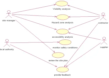
DIVERCITY initially intended to use use-cases and UML as means of requirements capture. Technical team also supported to use of UML for requirements capture. Therefore, use case driven analysis were selected for requirements elicitation and analysis and rational rose enterprise edition software tool of UML
FIG. 1: A use case diagram for space and safety evaluation on site for a duration in actual construction
3.1.2. The Contextual Design Technique
The lack of synthesis between use cases to capture system usage aspects is the main drawback of use case modelling. That is to say, use case driven requirements analysis is just a loose collection of use cases,
[image:6.595.89.444.94.351.2](Robertsons, 1999), (Regnell et al, 1995), (Christiansson et al, 2001). After the inadequacy of use case modelling for early requirements capture was realised, the project team looked for the alternatives for requirements capture process and due to its well worked out user centred approach, the Contextual Design method (Beyer and Holtzblatt, 1998) was chosen to take into account the end user work practice and interface requirements. Contextual Design approach is depicted in Fig. 2.
The following sections review the definition of contextual design and provide examples from DIVERCITY:
a. Vision:DIVERCITY adopted a vision for collaborative and integrated environments through the use of advanced IT. It contained seven key themes (Sarshar 2002).
• Model driven as opposed to document driven information management on projects (use of IFC standards).
• Life cycle thinking and seamless transition of information and process between life cycle phases.
• Use of past project knowledge (/ information) on new developments. • Dramatic changes in procurement philosophies, as a result of the internet. • Improved communications at all lifecycle phases, through visualisation. • Increased opportunities for simulation and what if analysis.
• Increased capabilities for change management and process improvement.
b. Storyboard: DIVERCITY developed a construction storyboard based on the vision. This storyboard was split into twelve scenes, each defining how DIVERCITY would interact with a specific construction process (Arayici, 2004). The storyboard included those scenes:
[image:7.595.71.415.365.516.2]c. User Environment Design: The new system must have the appropriate function and structure to support a natural workflow. The User Environment Design captures the floor plan of the new system. It shows each part of the system, how it supports the user's work, exactly what function is available in that part, and how the user gets to and from other parts of the system (Beyer and Holtzblatt, 1998). Objects and other knowledge representations were specified to meet user-induced requirements. Fig. 2 shows the progression from design to development.
TABLE 2: Storyboard Scenes through which DIVERCITY runs by providing collaborative environment (Arayici, 2004)
Scene 1 Check Constraints
Scene 2 Develop Alternatives Scene 3 Early Briefing
Scene 4 Stakeholder Involvement
Scale 5 Scale Down Detail
Scene 6 Lighting Simulation
Scene 7 Heating and Thermal Simulation
Scene 8 Acoustic Simulation
Scene 9 Constructability
Scene 10 Site layout initialisation and optimisation Scene 11 Space and safety evaluation
Scene 12 Progress monitoring
3.3.3. Incremental Prototyping with the End User Tests
As proposed by Kruchten (2000), DIVERCITY undertook continual validation testing as part of its incremental approach to software development. Testing was not comprehended as a single activity at the end of the project. The technical partners obtained continuous feedback on the evolving system functionality and quality. The user team continuously evolved their understanding of what the technology could offer, and what the shape and form of the DIVERCITY workspace would be:
Three iterative tests were undertaken for the functional requirements of the applications and their usability. The tests were performed by the distributed user team and the results and experiences were shared in collaborative sessions. In the storyboard, a number of use cases guided the functionality tests. The storyboard was modified and re-employed in each test phase. This resulted in effective and continuous re-tests of the applications in functionality, usability, performance and reliability and etc.
4.
RESEARCH METHODOLOGY FOR THE DEVELOPMENT OF
REQUIREMENTS ENGINEERING FRAMEWORK
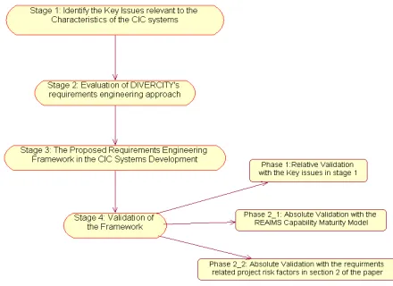
[image:8.595.74.514.130.450.2]The research is a case study based on the DIVERCITY project. This was conducted in four stages as shown in Fig. 3.
FIG. 3: Research Methodology
4.1 Stage 1: Identifying Key Issues Relevant to the Characteristics of the CIC Systems
Large-scale systems involving people and technology demand careful capture and modelling of requirements and architectural designs, before the low level system details begin to dominate the engineers’ attention and
significant resources are expended for system construction (Grunbacher et al, 2001, Silva, 2002).
TABLE 3: Key Issues for benchmarking and for validating the framework to be proposed.
Traceability through Process and Product Modelling
K1 Structuring and formalisation of the amount of knowledge captured by means of traceability
K2 Customising the traceability based on organisation and project specific goals
K3 The ability of handling the inherent complexities
K4 Conducting requirements management with process and product awareness
K5 Measuring the development process to characterize the components of the models in order to support quantitative analysis
K6 Quantitative assessment of influence of requirements changes and quantitative estimation of cost of development activities
Goal Oriented Requirements Engineering
K7 Completeness of requirements engineering
K8 The ability to keep requirements relevant and eliminate irrelevant requirements
K9 The ability to enable a shared understanding between users and developers
K10 Readability of the complex requirements document
K11 The ability to resolve the inconsistencies in requirements K12 Continuous traceability in the requirements engineering process
Essential and Incidental Complexities in Requirements Model
K13 Understanding about problem space
K14 Fit between the structure of the requirements model and the structure of world K15 Completeness and unambiguousness of requirements engineering model
Measurability of Quality Requirements
K16 Shared understanding about what to do
K17 Structuring the requirements specification for clear picture of user requirements K18 Conceptual differentiation of functional and quality requirements
K19 Influence of cultural attitude on requirements engineering process
K20 Quantification of non-functional requirements
K21 Traceability through requirements for sourcing the information K22 Care and attention given to the constraints and cost requirements
Requirements Fundamentals
K23 Testing the requirements for consistent and accurate requirements specification
K24 Relevance, coherency, consistency and connectivity in the requirements model K25 Balance between functional requirements and the other requirements in the specification
K26 Quality of structure and documentation of the requirements specification
K27 Capability to trap requirements related defects as early as possible and to leave out from design and implementation.
K28 Involvement and commitment of the stakeholders
Identifying and Involving the Stakeholders in the Development Process
K29 Involvement of the right stakeholders at the right time in the right subjects
K30 A feedback mechanism for a symbiotic communication and collaboration between the developers and stakeholders
Reconciling Software Requirements and Architectures K31 Bridging different levels of formality
K32 Modelling non-functional requirements
K33 Maintaining evolutionary consistency
K34 The fit between the system architecture and the way users works K35 Handling scale and complexity
K36 Involving heterogeneous stakeholders
Barriers to Industrial Uptake of Requirements Engineering
K37 Coverage of cost and benefits justifications
K38 Scalability of RE method to handle large sets of requirements
K39 The clarity and coherency of requirements specification
K40 Continuity of requirements capturing through the requirements elicitation, requirements analysis and downstream of the RE process
K41 The familiarity of end users with the RE techniques K42 Cost implementation and execution
K43 Equivalence between the available financial resources and the required financial resources
4.1.1. Traceability through product and process modelling
Process redesign is crucial for the implementation of CICs in the construction industry, because the construction industry is fragmented and the process awareness is very low in construction organisations. Betts (1999) stated the following steps for the success of re-engineering processes with IT:
• Develop business vision and goals and process objectives • Identify the processes to be re-engineered
• Understand and measure existing processes • Identify IT levers which will help push the changes • Design and build a prototype of the new process
New innovative systems often result from a change in the basic process of the business, although sometimes the process can only be changed by the introduction of a new system. Whatever the case, the change should be process led rather than IT led.
4.1.2. The goal-oriented requirements engineering
The CIC systems are to improve the quality of construction and increase the profit margins and efficient work. Therefore, completeness and coherency of requirements specification is important to cover all the stakeholders to work in a lean process. Because the stakeholders work in a complex environment, their requirements and expectations from the CIC systems will be complex, which results in requirements specification to be complex. Hence, readability of the specification is crucial for shared understanding. Furthermore, goals are good tools to capture the end users requirements because construction stakeholders are not well familiar with such systems. It is inevitable that requirements will change as the essential complexity grows in the development, which is manageable and simplified by means of continuous traceability in requirements engineering process.
4.1.3. Essential and Incidental Complexities in Requirements Models
The inherent understanding of distributed, collaborative integrated information systems for the construction industry does not exist between the construction practitioners and academics. The requirements engineering process should also compromise the incidental complexity. Because the construction industry is a complicated one, this complexity will be reflected to the requirements specification. Therefore, it is inevitable that there will be conflicts between the needs of different stakeholders, which add an extra layer to the complexity of the requirements specification. Consequently, the completeness and unambiguousness of the requirements specification and model are critical.
4.1.4. The Measurability of Quality Requirements
Shared understanding between the construction organisations at organisational level, a shared understanding between the construction stakeholders at project level and a shared understanding of what they exactly need from a CIC system is crucial for successful developments. For example, the DIVERCITY requirement capture process evolved based on a shared understanding.
The CIC technology provides sophisticated functionalities but ease of use of these functionalities, user-friendly interface and the other quality aspects should be taken into account properly, as they are important in convincing the decision makers to adopt the CIC systems.
Cultural attitude in employing requirements engineering used to occur in the early CIC prototype development, but its impact is becoming weaker and weaker while the awareness of the CIC community about requirements engineering rises.
4.1.5. Requirements Fundamentals
Furthermore, testing can help to simplify the incidental and essential complexities in the requirements models, which will help for a shared understanding and readability between the stakeholders and developers. Besides, versioning should be done for change and requirements managements.
4.1.6. Identifying and Involving the Stakeholders
Because the concept of CIC itself is an evolving issue, it is critically important to involve the right stakeholders who can provide significant contribution to the development and implementation. Subsequently, they will have a positive impression and willing to utilise CICs in their workplace. In terms of professional and project level, the right construction practitioners should be involved in the development at the right time in order to address the key bottlenecks they have experienced in their own professions.
4.1.7. Reconciling Software Requirements and Architectures
Depending on the success in the transition from the requirements specification to the system architecture, the system will reflect the requirements of the construction people, which is also relevant to the incidental
complexity. Because there are heterogeneous stakeholders involved in a CIC development, it is a big challenge to capture and model these requirements consistently and coherently while minimising the conflicts. Added to achievement in modelling these complex requirements, transforming the complex requirements model into system architecture is very much critical in the CIC development. The transformed system architecture should comply with the process model defined in the requirements model.
4.1.8. Barriers to Uptake of Requirements Engineering
One of the most difficult problems with improving the use of IT in construction is overcoming the
implementation problem, which requires a strategy definition. Factors that need to be considered are (Betts, 1999):
• Business processes are relevant to process modelling in requirements engineering in the CIC development. New innovative systems should be process led not IT led. However, many CIC system developments were not process led.
• Team members need to have the ability to convey progress and seek the advice and approval of, their peers. However, whilst it is not always possible to represent or obtain the views of every interested party, the chosen team members should fairly reflect the views of all interested parties. • System integration implies an integrated computer environment that consists of implementing more
than one solution. Project data passes from one solution to another through integration platform. • Once the implementation of requirements engineering process starts, it is important to complete it
within the allocated timescale and resources.
4.2. Stage 2: Evaluation of the DIVERCITY Requirements Engineering Approach
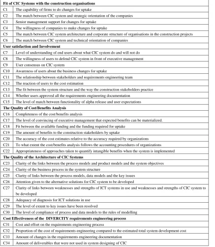
A broad research study was conducted whose objectives were to identify key factors by which RE techniques can be assessed and success of RE techniques can be observed after they are implemented. 34 key factors were identified, which are clustered into 5 different categories (Arayici, 2004). These categories are: i) fit of the CIC systems with the construction organisations, (ii) user satisfaction and involvement, (iii) the costs & benefits analysis, (iv) the quality of system architecture and (v) cost effectiveness of the applied RE process. Table 4 shows the criteria under these categories.
A critical elaboration of DIVERCITY’s approach has been conducted based on the case study findings and survey findings, which were obtained through a survey using the criteria in Table 4. Fig. 4 shows the results of the evaluation of DIVERCITY’s approach.
TABLE 4: set of criteria for the evaluation of DIVERCITY’s approach
Fit of CIC Systems with the construction organisations C1 The capability of firms to do changes for uptake
C2 The match between CIC system and strategic orientation of the companies
C3 Senior management support for changes for uptake
C4 The willingness of companies to make changes for uptake
C5 The match between CIC system architecture and corporate structure of organisations in the construction projects
C6 The match between CIC system and technical orientation of companies
User satisfaction and Involvement
C7 Level of understanding of end users about what CIC system do and will not do C8 The willingness of users to defend CIC system in front of executive management
C9 User consensus on CIC system
C10 Awareness of users about the business changes for uptake
C11 The relationship between stakeholders and requirements engineering team C12 The reaction of users to the cost estimation
C13 The fit between the system structure and the way the construction stakeholders practice
C14 Whether users approved all the requirements engineering documentation
C15 The level of match between functionality of alpha release and user expectations The Quality of Cost/Benefits Analysis
C16 Completeness of the cost/benefits analysis
C17 The level of convincing of executive management that expected benefits can be materialized.
C18 Fit between the available funding and the funding required for uptake C19 The amount of benefits to the construction stakeholders by uptake
C20 The accuracy of the cost estimates relative to the accuracy required by organizations
C21 To what extent the cost/benefits analysis follows the accounting procedures of organizations
C22 Appropriateness of approaches taken to quantify intangible benefits when the system is implemented The Quality of the Architecture of CIC Systems
C23 Clarity of the links between the process models and product models and the system objectives
C24 Clarity of the business process in the system structure
C25 Clarity of links between the process models, data models and the key issues C26 Attention given to the alternative solutions for CIC system to be developed
C27 Clarity of links between weaknesses and strengths of ICT systems in use and weaknesses and strengths of CIC system to be developed
C28 Adequacy of diagnosis for ICT solutions in use
C29 The level of extent to key issues have been resolved
C30 The level of compliance of process and data models to the rules of modelling
Cost Effectiveness of the DIVERCITY requirements engineering process
C31 Cost and effort on the requirements engineering process
C32 Proportion of the cost of requirements engineering compared to the estimated total system development cost C33 Amount of changes in the requirements engineering documentation
C34 Amount of deliverables that were not used in system designing of CIC
Storyboarding and incremental prototyping techniques increased the process awareness and entailed the users’ involvement intensively. Due to storyboarding and incremental prototyping techniques, DIVERCITY was a process led development, which was the main strength of the DIVERCITY requirements engineering process. In regard to user satisfaction and involvement, (see Fig. 4) due to lack of traceability, not many people were sure what the new system provided until the incremental prototyping. Owing to inadequacy in handling the
complexities in many respects in the development, the users involved in the project could not pursue the development properly until the storyboarding and prototyping. Besides, requirements management were initially conducted with lack of process and product awareness.
traceability did not happen until storyboarding. DIVERCITY’s approach failed in respect to the quality of cost benefit analysis because it was not strategically taken into account. It did not occur and thoroughness given to the constraints and cost requirements hardly existed in DIVERCITY (see Fig. 4).
Evaluation results of DIVERCITY's approach
0 0.5 1 1.5 2 2.5 3 3.5 4 4.5
C1 C2 C3 C4 C5 C6 C7 C8 C9 C10 C11 2C1 C13 C14 C15 C16 C17 C18 C19 C20 C21 C22 C23 C24 C25 C26 7C2 C28 C29 C30 C31 C32 C33 C34 The criteria
A
v
er
a
g
e m
a
rk
[image:13.595.76.527.117.295.2]s
FIG. 4: Evaluation of DIVERCITY’s approach
In regard to the quality of the system architecture, the clarity of links between the process model, data model, system objectives and clarity of the business process in the system architecture were established well (see Fig. 4). Many aspects such as collaboration, distribution, integration, common data exchange, etc, were addressed. The clarity of links between the process and data models and key issues were improved later in the project but not fully resolved. There was no benchmarking with the existing systems or software in use in the construction industry in the DIVERCITY user requirements.
Cost effectiveness is the other dimension that DIVERCITY’s approach failed. Doing cost effectiveness analysis of the utilised requirements engineering techniques can help increase the productivity with an allocated budget. On the other hand, for commercial development, keeping the cost reasonable for the requirements engineering activities is important.
There are five different causes identified in DIVERCITY’s approach, which resulted in under delivery. These are: (i) the requirements engineering process itself, (ii) human communication within requirements engineering process, (iii) knowledge development, (iv) documentation of requirements and (v) management. By overcoming these causes in the DIVERCITY requirements engineering process, a framework for effective CIC development for the uptake is proposed in section 3.4 and described in details.
4.3. Stage 3: The Proposed Requirements Engineering Framework in the CIC systems
Development
As a result of evaluation of DIVERCITY’s case study described earlier and also the findings from the literature about the other CIC systems development cites in section 1, the framework in Fig. 6 proposes a strategic approach to user-oriented CIC systems development for the construction industry.
Phase 1 - Project Blast-of:The steering committee, which is comprised of client, the main users, lead
developers, technical and business experts, defines the blastoff objectives and stakeholders. If all the stakeholders are not defined, it is likely to miss some of the requirements. Furthermore, a preliminary cost estimate is also produced. An early assessment of the risks that the project is likely to face is also made. The project scope and boundaries are defined to decide how much work will be required before requirements capture. In addition, budget and time allocated are also relevant to the scope. The first version of the requirements deliverable is produced and it covers the issues in stage 1.
Phase 2 - Requirements Elicitation:Elicitation activity is both a study of the current work practices and an
• Flow model: The flow model will represent the coordination, communication between the stakeholders and their responsibilities and duties.
• Sequence Model: The sequence models show the progress of the construction project by relating the activities to each other, which denotes the construction supply chain.
• Artefact Model: The construction stakeholders use tangible and intangible artefacts, which causes fragmentation and lack of productivity due to their nature and determination. Modelling these artefacts will enable the development team to evaluate those artefacts and the interaction between them. Accordingly, problems are identified and the solutions can be formulated.
• Culture Model: Capturing and modelling cultural aspects will ease developing a rational process model. Involvement of end users in culture modelling will contribute to better realise these cultural barriers.
• Physical Model: Any system lives with the constraints of the physical environment in which people have some control over their environment. Studying the workplace provides important clues to the way people structure the work.
The second version of requirements specification is produced. It updates the first version and incorporates raw requirements.
Phase 3 - Building a Shared Understanding (Requirements Analysis): It is not enough to understand the
stakeholders’ needs. There should also be a shared understanding, which is developed through conversation and mutual inquiry into the meaningful facts about the end users’ work so that different members of the development team learn the perspectives of others. Three main stages are indicated in the framework for building a shared understanding. These are explained below:
• Establishing a shared understanding with interpretation session. This assists the team with what to record, data analysis in order to develop a shared understanding.
• Improving the shared understanding with consolidation. Once a shared understanding emerges, this phase assists the team to establish common structure and pattern of work aided by consolidated work models and affinity diagrams, which reveals common and key issues in a hierarchy. • Communicating to the stakeholders:this aims to assists the users with their understanding of the
project design direction and to provide meaningful ways for them to comment and contribute ideas with knowledge. This also facilitates provides for immediate feedback and it will reveal the end users’ work practice as a coherent whole.
The third version of the requirements specification deliverable is produced after building the shared understanding.
Phase 4 - Process Modelling (Requirements Modelling): The goal of process modelling is to look across the
different consolidated models and to see a unified picture of work practice.
Discussing each model in turn leads to a synthesis of issues across models. The team can absorb one coherent aspect of work at a time, making the complexity manageable and improves a shared understanding and sense of direction for system design. Subsequently, work models give the team a handle for both incidental and essential complexities of construction activities. A good process designing will define explicit steps for process
modelling. These steps are briefly explained below.
• Walking the Data:Walking the affinity diagram and consolidated work models focuses the team on specific aspects of work. After walking the affinity diagram and work models, the team thinking is crystallised by making a list of the most important issues from the models before visioning. • Visioning:A visioning session gives the team a chance to choose a starting point and spin it out
into a story about the new work practice transformed by technology.
• Evaluation and Integration: After visioning session, there will be multiple visions, each suggesting a different design direction or addressing a different part of the work. Creating a better solution by identifying elements and synthesising them by preserving the best parts and extending them to overcome any defects is carried out through the evaluation and integration session. The whole process is designed to bring a disparate, cross-functional team of people to consensus and a solid shared understanding.
possible platforms, whether specific technology is sufficiently reliable and whether it meets the requirements and user interface possibilities. In the end, process model contains a number of scenes that tell a detailed story of a specific piece of construction duty. It will form the basis for system design.
The fourth version of the requirements specification is produced, which reflects the evolutionary progress of the requirements engineering process and explains how the process model is derived from the consolidation models and visioning.
Phase 5 - System Design: This is the stage where the user requirements are transformed into a system design.
The challenge is to keep the system design coherent without missing any single requirement so that it supports the users and fits with their expectations while transforming their work practice.
User environment design is the technique for the transformation from process model, to system design. It enables to build a single coherent structure that supports multiple different tasks performed by different roles in a construction project. It represents the key distinctions, which are called as focus areas, for supporting work practice with software systems. They contain, organise and present the objects that users need to work on. In addition, they include the links, constraints, issues and so on.
The user environment design bridges the natural rotation between sequential and structural thinking. Text-based storyboarding and use cases are sequential. They indicate a single series of events in order. The user environment design, and object models of UML are structural. They show all parts of the system and how they interrelate. Since process modelling is sequential, it includes threads for system design; the user environment design is structural and reveals how all the threads fit together coherently.
As the system is a mix of hardware and software, the same focus areas in the user environment represent physical hardware places and software, which is the representation of the total system including hardware, software, and documentation.
Fifth version of the requirements specification deliverable is produced. It explains how the new system behaves and organises its functions in a way that makes sense for the user. The following sections are included in this version.
• Overview: It gives an overview of the whole system, its goals and its business structure.
• Supporting data: It reflects the evolutionary progress because it is important to emphasise how a
design is built and responds to end users’ requirements.
• Functional Requirements: This is the basic definition of what the system does. It is organised by
focus areas in the user environment design.
• Quality requirements: Additional requirements on the system such as performance, reliability,
maintainability, usability, platform supported, etc. are listed..
• Objects: The objects in the focus areas are listed. The meaning and usage of objects across focus
areas are described. These objects have associations with the artefacts explained in the artefacts modelling.
• External interfaces: External interfaces to the system are collected and described.
Phase 6 - Use Case and Object Modelling with UML: he storyboarding and the user environment design are
FIG. 5: The proposed requirements engineering framework
1) Project
Blastoff
2) Requirements
Elicitation
Work
modelling
Flow modelling Artefacts modelling Sequence modelling Culture modelling Physical modelling3) Building a shared
understanding
1) Interpretation sessions
2) Consolidation 3) Communication to stakeholders
4) Process
Modelling
5) User
Environment Design
6) Use case
modelling
7) Object Modelling
and Coding
8) Alpha phase
Testing
9) Beta Phase
Testing
10) Final
Phase Testing
1st version of requirements specification is produced
2nd version of requirements specification is produced
3rd version of requirements specification is produced
4th version of requirements specification is produced
5th version of requirements specification is produced
6th version of requirements specification is produced
7th version of requirements specification is produced 8th version of
requirements specification is produced
It is always an issue to decide what should be specified by a use case. Therefore, use case modelling after storyboarding and user environment design helps to define use cases at the right scale. In other words, the storyboard defines what the user will do and the user environment design defines the functions. Use cases work out precisely what happens when the user operates these functions.
The sixth version of the requirements specification is produced. It is the expansion of the fifth version and explains the results of smooth transition from user requirements to the system design and modelling.
Phase 7 - Incremental Prototyping with the End Users Tests: Prototyping with end user testing is an agile
process for analysis and validation of requirements and a way of achieving the quality by eliminating the errors in the system. It requires intensive user involvement, non-functional requirements, process awareness, iterative and incremental improvement, intensive teamwork and collaboration and a high level of systemic thinking.
Furthermore, users can communicate to the developers and they can see how their responses shape the system and their interest and involvement in the tests of the early prototypes leads to easier acceptance and adoption of the system to the industry. A coherent association between the agile process and previous techniques is established. (The details about the stages in the prototyping can be found at Arayici, 2004).
• Alpha Testing: System components are tested as stand-alone by all the end users situated at
different locations. The main objectives are the functionality and usability testing. Each product’s conformity is examined against the use cases. Seventh version of the deliverable is produced and disseminated to the relevant parties.
• Beta Phase Testing: Activities undertaken by the different construction practitioners in the focus
areas of the user environment design and the communication between the focus areas for exchange of information are tested. Because use cases are derived from the user environment design, which enables retesting the whole functionalities from the alpha phase. This is useful observing the expected improvements between the alpha and beta tests. Furthermore, new defects discovered at the beta phase are recorded. Eighth version of the deliverable is produced and disseminated to the relevant parties
• Final Phase Testing: At this stage, the system is tested as a whole. The test design includes test
cases from the process model. It is a multifaceted test to assess the operation of the whole system in functionality, reliability, performance and usability. System testing relies on the process model, which entails the interaction of the components, exchange of information between the distributed stakeholders and synchronous or asynchronous type of collaboration. Final phase continues iteratively until the end users are satisfied with all the test criteria because final phase testing also covers the issues of acceptance by the end users. This is critically important for the implementation of the system in the industry.
Ninth version of the deliverable is produced and distributed to the relevant parties. User reactions, validation of the requirements and the system and exploitation of the system in the industry are addressed.
4. 4. Stage 4: Validation of the Framework
Because empirical validation requires the real implementation of the framework in a CIC development, it is not possible to conduct the empirical validation at the moment. However, a comprehensive theoretical validation is carried out in two steps: relative validation, absolute validation. The following sections will explain the relative and absolute validation respectively.
4.4.1. Relative Validation
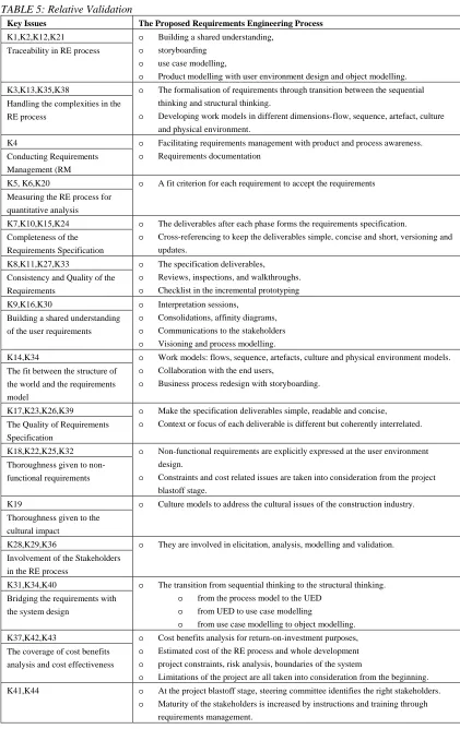
The key issues explained in stage 1 of the research methodology were used for relative validation. The key issues were designed to use for improving the requirements engineering processes before implementation. Therefore, using the key issues was more appropriate than the criteria, which are designed for measuring the success of requirements engineering processes after the implementation. Table 5 shows the relative validation with the key issues.
TABLE 5: Relative Validation
Key Issues The Proposed Requirements Engineering Process
K1,K2,K12,K21
Traceability in RE process
o Building a shared understanding,
o storyboarding
o use case modelling,
o Product modelling with user environment design and object modelling. K3,K13,K35,K38
Handling the complexities in the RE process
o The formalisation of requirements through transition between the sequential thinking and structural thinking.
o Developing work models in different dimensions-flow, sequence, artefact, culture and physical environment.
K4
Conducting Requirements Management (RM
o Facilitating requirements management with product and process awareness.
o Requirements documentation
K5, K6,K20
Measuring the RE process for quantitative analysis
o A fit criterion for each requirement to accept the requirements
K7,K10,K15,K24 Completeness of the Requirements Specification
o The deliverables after each phase forms the requirements specification.
o Cross-referencing to keep the deliverables simple, concise and short, versioning and updates.
K8,K11,K27,K33
Consistency and Quality of the Requirements
o The specification deliverables,
o Reviews, inspections, and walkthroughs.
o Checklist in the incremental prototyping K9,K16,K30
Building a shared understanding of the user requirements
o Interpretation sessions,
o Consolidations, affinity diagrams,
o Communications to the stakeholders
o Visioning and process modelling. K14,K34
The fit between the structure of the world and the requirements model
o Work models: flows, sequence, artefacts, culture and physical environment models.
o Collaboration with the end users,
o Business process redesign with storyboarding.
K17,K23,K26,K39
The Quality of Requirements Specification
o Make the specification deliverables simple, readable and concise,
o Context or focus of each deliverable is different but coherently interrelated.
K18,K22,K25,K32
Thoroughness given to non- functional requirements
o Non-functional requirements are explicitly expressed at the user environment design.
o Constraints and cost related issues are taken into consideration from the project blastoff stage.
K19
Thoroughness given to the cultural impact
o Culture models to address the cultural issues of the construction industry.
K28,K29,K36
Involvement of the Stakeholders in the RE process
o They are involved in elicitation, analysis, modelling and validation.
K31,K34,K40
Bridging the requirements with the system design
o The transition from sequential thinking to the structural thinking.
o from the process model to the UED
o from UED to use case modelling
o from use case modelling to object modelling. K37,K42,K43
The coverage of cost benefits analysis and cost effectiveness
o Cost benefits analysis for return-on-investment purposes,
o Estimated cost of the RE process and whole development
o project constraints, risk analysis, boundaries of the system
o Limitations of the project are all taken into consideration from the beginning. K41,K44 o At the project blastoff stage, steering committee identifies the right stakeholders.
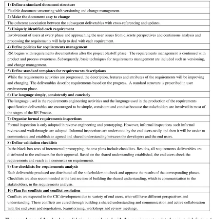
4.4.2. Absolute Validation
[image:19.595.61.496.219.668.2]Absolute validation is conducted in two steps. In the first step, the proposed RE Process is assessed against the top ten guidelines of REAIMS assessment model (Nikula, 2003) and in the second step, requirements related project risk factors (Nikula and Sajaniemi, 2002), (Carr, 2000) are used. Nikula (2003) stated that the concept of maturity is a good means of describing and improving the quality of the practices in system development. REAIMS maturity model has three levels and its assessment includes evaluation of 66 good RE practices. Top ten practices should be met by the requirements engineering process to achieve the level 1 maturity, which is necessary before the implementation of the requirements engineering process. Table 6 shows the evaluation of the proposed requirements engineering process according to the top ten practices of REAIMS model for level 1 maturity.
TABLE 6: Evaluating the level 1 maturity according to the REAIMS assessment model for the absolute validation (first step)
1) Define a standard document structure
Flexible document structuring with versioning and change management.
2) Make the document easy to change
The coherent association between the subsequent deliverables with cross-referencing and updates. 3) Uniquely identified each requirement
Involvement of users at every phase and approaching the user issues from discrete perspectives and continuous analysis and processing the requirements will help to deal with each requirement.
4) Define policies for requirements management
RM begins with requirements documentation after the project blastoff phase. The requirements management is continued with product and process awareness. Subsequently, basic techniques for requirements management are included such as versioning, and change management.
5) Define standard templates for requirements descriptions
While the requirements activities are progressed, the description, features and attributes of the requirements will be improving and changing. The deliverables describe requirements based on the progress. A standard structure is prescribed in user environment phase.
6) Use language simply, consistently and concisely
The language used in the requirements engineering activities and the language used in the production of the requirements specification deliverables are encouraged to be simple, consistent and concise because the stakeholders are involved in most of the stages of the RE Process.
7) Organise formal requirements inspections
Formal inspection is only adopted in reverse engineering and prototyping. However, informal inspections such informal reviews and walkthroughs are adopted. Informal inspections are understood by the end users easily and then it will be easier to communicate and establish an agreed and shared understanding between the developers and the end users.
8) Define validation checklists
In the black-box tests of incremental prototyping, the test plans include checklists. Besides, all requirements deliverables are distributed to the end users for their approval. Based on the shared understanding established, the end users check the requirements and reach at a consensus on requirements.
9) Use checklists for requirements analysis
Each deliverable produced are distributed all the stakeholders to check and approve the results of the corresponding phases. Checklists are also recommended at the last section of building the shared understanding, which is communication to the stakeholders, in the requirements analysis.
10) Plan for conflicts and conflict resolution
Conflicts are expected in the CIC development due to variety of end users, who will have different perspectives and
understanding. These conflicts are cured through building a shared understanding and communication and active collaboration with the end users and negotiation, brainstorming, workshops and review meetings.
The second step of the absolute validation is conducted with the requirements related project risk factors (Carr, 2000). These factors are listed in table 7 together with the techniques that addresses the factors in the Proposed RE Process. The Proposed RE Process firstly tries to alleviate the likelihood of these risks, and secondly it should make presence of these risks apparent so that appropriate actions can be taken.
Consequently, the absolute validation of the RE framework process is completed with the completion of the second step of the absolute validation.
Table 7: The Absolute validation with the project risk factors (second step)
Risk factor The Proposed RE Process to mitigate the risk factors
Misunderstanding the requirements Documenting requirements Interacting with the stakeholders
Reviewing RD (Requirements Documentation) and requirements, Process modelling and product modelling
Prototyping with the end users tests
Lack of adequate user involvement Communication to stakeholders, work modelling,
process modelling, UED,
use case modelling, user tests, etc.
Failure to manage end user expectations Interacting with users Documenting requirements Prioritising requirements
Validating requirements with prototypes
Changing scope/objections Documenting business goals, context and requirements
Requirements Management including baselining RD and requirements, change requests
Lack of frozen requirements Documenting business goals and objectives Requirements management
Documenting requirements Change management
Conflict between the user departments Building a shared understanding, consolidation, affinity diagrams, Process modelling, UED, use case modelling
Documenting requirements Meetings with the stakeholders Reviewing RD and requirements Prototyping with end user tests
Incomplete requirements and specification Documenting requirements
Work modelling, text-based storyboarding or process modelling, UED Consolidation and affinity diagrams and communication to the stakeholders Reviewing the RD and requirements
End user tests for validation
Ambiguous and vague requirements Documenting requirements Building shared understanding
Process modelling, UED, use case modelling, Requirements validation
5.
CONCLUSION
This paper elaborated on the requirements engineering concept, which is a parameter for the effective
supplemented by two additional constructs. These are (i) tool support for requirements management, (ii) training. Therefore, further investigation is required to enhance these constructs within the framework for its
implementation. This opens a new research angle for further studies with regard to requirements engineering in the construction IT area for the effective development and uptake.
6.
REFERENCES
Alshawi M and Faraj I (2000), Integrated construction environments: technology and implementation
Construction Innovation, Vol 2, No 1.
Alshawi M., Putra C W, and Faraj I. (1996), A structured concept for objects life cycle in integrated environments, Microcomputers in Civil Engineering, Blackwell, 12, 339-351.
Aouad G. and Wafai M.H. (2002), Implementation of information technology in the construction industry: the conceptual methodology approach, 2nd International Postgraduate Research Conference in the Built and Human environment, University of Salford.
Aouad G., Marir F., Child T., Brandon P., and Kawooya A. (1997), A construction integrated databases- linking design, planning and estimating, International Conference on Rehabilitation and Development of civil engineering infrastructure systems, American University of Beirut, Lebanon.
Arayici, Y, (2004), Requirements engineering in innovative systems development for the construction industry, PhD Thesis, SCPM, University of Salford, UK.
Arayici, Y. and Aouad, G. (2004), DIVERCITY: distributed virtual workspace for enhancing communication and collaboration within the construction iIndustry”. European Conference on Product and Process Modelling in the Building and Construction Industry (ECPPM), Istanbul, Turkey, 415-422.
Bazjanac, (2004), Virtual building environments (VBE)-applying information modelling to buildings,
Proceeding of European Conference on Product and Process Modelling in the Building and Construction Industry (ECPPM) , Istanbul, Turkey, 41-48.
Betts M. (1999), Strategic management of IT, ISBN 0 632 04026 2, Blackwell Science.
Beyer H, Holtzblatt K, (1998), Contextual design. defining customer-centred sSystems, Morgan Kaufmann Publishers, San Francisco.
Carr J. (2000), Requirements engineering and management: the key to designing quality complex systems, TQM Magazine, Vol 12, No 6, 400-407, MCB University Press, ISSN 0954-478X.
CHAOS Report (1995), Software development report. The Standish Group, published at www.standishgroup.com
CHAOS Report (2000), The Software development report. The Standish Group, published at www.standishgroup.com
Christiansson P, Svidt K, Skjærbæk J O, and Aaholm R, (2001) User requirements modelling in design of collaborative virtual reality design systems, International Conference on Construction Information Technology, Mpumalanga, South Africa.
Cysneiros, L.M., (2002), Requirements engineering in health care domain, Proceedings RE02 International Conference on Requirements Engineering, IEEE Computer Society Press, Requirements Specification. IEEE Transactions on Software Engineering, 20(10): 760-773.
Divercity Handbook (2003), The Divercity Project: A virtual toolkit for construction briefing, design and management, University of Salford, UK.
Faraj I., Alshawi M., Aouad G., Child T. and Underwood J. (2000), An IFC web-based collaborative
construction computer environment: WISPER, Proceedings of the National Conference on Objects and Integration for AEC, UK, ISBN 186081 3771.
Grunbacher, P. and Briggs B. (2001), Surfacing tacit knowledge in requirements negotiation: experiences using EasyWinWin, Proceedings Hawaii International Conference on System Sciences, IEEE Computer Society.
Hoffmann H., and Lehner F. (2001), Requirements engineering as a process factor in software projects, IEEE Software 18(4): 58-66.
Keil M., Cule P.E., Lyytinen K. and Schmidt R.C., (1998). A framework for identifying the software projects risks Communication of the ACM, Vol. 41, 76-83.
Kruchten P. (2000), The rational unified process – an introduction, Second Edition, Addison-Wesley, ISBN 0-201-70710-1.
Laiserin J. (2003), AEC Interoperability and the BLIS Project, CADALYST Magazine, www.cadalyst.com/cadalyst/
Lee A., Ponting A.M., Aouad G., Wu S., Koh I., Fu C., Cooper R., Betts M., Michail K. and Fischer M.(2003), Developing a vision of nD-enabled construction, 3D to nD modelling project, University of Salford, UK.
Lundh E. and Sandberg M. (2002), Time constraint requirements engineering with extreme programming -an experience report, IEEE Joint International Requirements Engineering Conference, Essen, Germany.
Molina J.M. and Martinez M. (2004), XML Based data model for the Spanish AEC sector Proceeding of European Conference on Product and Process Modelling in the Building and Construction Industry (ECPPM), Istanbul, Turkey, 149-154.
Nikula U. (2003), Experiences from Lightweight RE Method Evaluations, IEEE International Workshop of Comparative Evaluation in Requirements Engineering, Monterey Bay, California, USA, IEEE Computer Society. 53-60.
Nikula U. Sajaniemi J. (2002), A Lightweight Combination of Proven RE Techniques, IEEE Joint International Requirements Engineering Conference, Essen Germany
Regnell B., Kimbler K., Wesslen A. (1995). Improving the use case driven approach to requirements
engineering, Proceedings Second IEEE International Symposium on Requirements Engineering, York, UK.
Robertson S. and Robertson J. (1999), Mastering requirements engineering process, ACM Press, ISBN 0201360462, Addison Wesley.
Sarshar M., Christiansson P, and Winter J (2004), Towards virtual prototyping in the construction industry: the case study of the DIVERCITY project, World IT for Design and Construction (INCITE) Conference, Designing, Managing and Supporting Construction Projects through Innovation and IT solutions, Langkawi Malaysia, 581-8.
Sarshar M., Tanyer M., Aouad G., Underwood J.(2002), A vision for construction IT 2005-2010: two case studies, Engineering, Construction & Architectural Management, Vol 9, No 2.
Silva A. (2002), Requirements, domain and specifications: a viewpoint-based approach to requirements engineering. Proceedings of ICSE (IEEE International Conference on Software Engineering), IEEE computer Society Press.
Steinman (2004), MOBIKO, Mobile cooperation in the construction industry based on wireless technology, Proceeding of European Conference on Product and Process Modelling in the Building and Construction Industry (ECPPM) , Istanbul, Turkey, 521-526.
Sun M. and Aouad G. (2000), Integration technologies to support organisational changes in the construction industry, 7th ISPE International conference on Concurrent Engineering, Lyon, France, 596-604.
Szigeti F.and Davis G. (2003), Portfolio and asset management: performance requirements and the IAI-NA PAMPer+ED project, International Centre for Facilities.