International Journal of Emerging Technology and Advanced Engineering
Website: www.ijetae.com (ISSN 2250-2459,ISO 9001:2008 Certified Journal, Volume 3, Issue 7, July 2013)
89
Network Recovery of Dual Link Failure for Multiple Drain
Nodes
Brijesh A. Bhandari
1, Deepali B. Gothawal
21
Pursuing M.E. Computer, D. Y. Patil Computer Engineering, Akurdi, Pune
2Assistant Professor Department of Computer Engineering, D. Y. Patil COE, Akurdi, Pune
Abstract— As the Internet developed gradually into a ubiquitous communication infrastructure and takes an increasingly central role in our communications, the slow convergence of routing protocols after a network failure becomes a major problem. Failures in network usually begin when one of its parts failed. When this happens, nearby nodes connected links must then take up the slack for its failed components. This overloads nodes and links, causing them to fail as well, prompting additional nodes and links to fail in a vicious cycle. To assure fast recovery from link and node failures in IP networks, the paper present a new scheme from failure in IP network with Color tree calculation using generalized colored tree algorithm. The primary scheme provides recovery for up to two link failure along a path with single Drain Node. The proposed technique requires multiple drain networks to recover from dual link failure. The goal of this paper is to embellish the robustness of the network to dual-link failures. Data fusion technique is added to existing method to improve network performance. To this end, a new technique is to be developed that combine the positive aspects of the various single-link and node failure recovery techniques. Paper presents and analyzes its performance with respect to scalability, load distribution, and backup path lengths after a failure. The System provides fast recovery from Single and dual link failure from Multi Drain Network.
Keywords— Node and Link Failure, Fast Recovery, Colored Trees, SimCT Algorithm, Data Fusion
I. INTRODUCTION
The Internet has evolved to be a global infrastructure supporting critical applications like, trading system, online games etc. To such a network, survivability is a stringent requirement in that services interrupted by network failures must be recovered quickly. However, failures are common in IP networks either because of maintenance of system or accidents. Several mechanisms have been proposed to give fast recovery from failures in the IP network. Using one of these fast recovery methods, the recovery time is mainly decided by the time it takes to discover the network failure. This can typically be done, using signaling from the physical layer or a failure detection protocol like BFD.
This is a significant improvement over the recovery times achieved by a normal routing reconvergence, which typically takes several seconds to recover.
One approach to achieve disjoint multipath routing in packet switched IP networks is to employ colored trees [8] concept. In this approach, every node in the network has two neighbors to the drain node: red and blue. A packet forwarded from a source is marked with one of the two colors. An intermediate node forwards a packet to its preferred neighbor based on the destination (drain) address and color of that packet. Thus, for every drain node, the routing table at any node has only two entries. As paths are augmented in a sequential fashion in the path augmentation technique, the maintenance of the trees is difficult in the presence of failures. Node or link failure may result in invalidating the paths for several nodes in a cascading fashion. While the trees may be reconstructed entirely because of failure in the network, such a total reconstruction of the trees is both unnecessary and it will result in a high overhead. As all algorithms based on path augmentation suffers from this limitation, The SimCT algorithm [8][15] offers following advantages compared to the earlier algorithms that are based on path augmentation: (1) the SimCT algorithm reduces the message overhead required to construct the colored trees by 40 percent; (2) the average path lengths obtained using the this algorithm is lesser than those obtained using path augmentation approaches; (3) the number of nodes whose paths are affected by a failure under the this algorithm will never be more than those affected by path augmentation approaches; and (4) this algorithm can be used to construct colored trees in a multiple drain networks. Message overhead can be reduced by using data fusion approach with this algorithm.
International Journal of Emerging Technology and Advanced Engineering
Website: www.ijetae.com (ISSN 2250-2459,ISO 9001:2008 Certified Journal, Volume 3, Issue 7, July 2013)
90
II. RELATED WORK
As the Internet evolves into a ubiquitous communication infrastructure and supports increasingly important services, its dependability in the presence of various failures becomes critical. Failures in communication networks are common and can result in substantial losses. In order for IP Network to become a full fledged carrier grade transport technology, a native Network failure recovery scheme is necessary that can correct failures in the order of milliseconds.
2.1 Recovery from Dual-Link Failures using Tunneling
To recover from arbitrary dual-link failures [2], this method assign up to four addresses per node one normal address and up to three protection addresses. These addresses are used to identify the endpoints of the tunnels carrying recovery traffic around the protected link. The default (normal) address of a node is μ 2 N denoted by μ0. This acts as the primary address for the routing protocol. In addition, there are three backup addresses denoted by μ1,
μ2 and μ3, which are employed whenever a link failure is encountered. The links connected to node μ are divided into three protection groups, denoted by Lμ1, Lμ2 and Lμ3. Node u is associated with three protection graphs Gμi(N, L /Lμi), where i=1, 2, 3. The protection graph Gui is obtained by removing the links in Lui from the original graph G. The highlight of this approach is that each of the three protection graphs is two-edge connected by construction. Let Sug = {ν | u - ν Є Lug} denote those nodes that are
connected to μ through a link that belongs to Lμg. Nodes in Sμg are the only nodes that will initiate tunneling of packets (to protection address μg) upon failure of the link connecting node.
A. Computing Protection Graphs
The decomposition of the graph into three protection graphs for every node μ Є G is achieved by temporarily
removing node μ and obtaining the connected components
in the resultant network. If the network is two-vertex-connected, then removal of any one node will keep the remaining network connected. If the network is only one-vertex-connected, removal of node μ may split the network into multiple connected components.
In such a scenario, consider every connected component individually. Assign the links from a connected component
to node μ into different groups based on further
decomposition and compute the protection groups. Then combine the corresponding protection groups obtained from multiple connected components.
The procedure for constructing the protection graphs for node u is shown below.
1. Remove node u and all the links connected to node u. The remnant graph will consist of one or more
connected components. Let C denote the set of
connected components.
2. For every connected component c∈ C, we denote the set of links connecting node u and nodes in c in G by
Luc. For component c, perform the following steps: 2.a) Decompose the connected component c into two edge connected components. Let Dc denote the set of two-edge-connected components.
2.b) Reintroduce node u and its links to
component c, while retaining the
two-edge-connected components. We denote this new
subgraph of G by Guc. We denote the link
protection groups associated with this component by Luic (i = 1, 2, 3).
2.c) If the number of two-edge connected components in c is exactly 1, i.e., |Dc| = 1, then
2.c.i) If |Luc| = 3, i.e., there are exactly three links from node u connecting to nodes in the component, then assign one link each to the three groups Lu1c, Lu2c and Lu3c.
2.c.ii) If |Luc| > 3, of all the edges from node u
in Guc, assign at least two edges to group Lu1c
and the remaining edges to group Lu2c. The third group does not have any links associated with it.
2.d) If |Dc| > 1, then
2.d.i) As G is three-edge connected, every
two-edge connected component d ∈ Dc that is
connected to only one other component d_ ∈ Dc
has at least two links connecting to node u from
the nodes in d. Therefore, for every such
component d ∈ Dc, divide the links connecting the component to u into two groups Lu1c and Lu2c
such that each group has at least one link.
2.d.ii) For every link connected to u in Guc that is not considered in step 2.d.i, assign it randomly to either Lu1c or Lu2c.
3. Combine the corresponding groups obtained across different connected components to obtain the final protection groups.
4. We obtain the three protection graphs Gui(N,L \ Lui), i = 1, 2, 3.
International Journal of Emerging Technology and Advanced Engineering
Website: www.ijetae.com (ISSN 2250-2459,ISO 9001:2008 Certified Journal, Volume 3, Issue 7, July 2013)
91
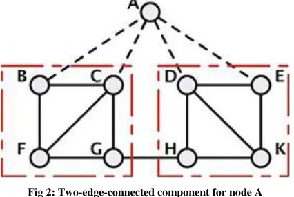
[image:3.612.54.281.200.298.2]Consider the example network in Fig. 1. The network is three edge and two vertexes connected. The protection graphs for node A is obtain by, removing node A and obtain the decomposition of the network into connected components.
[image:3.612.63.276.375.518.2]Fig 1: Network with colored trees rooted at node A. (a) Red tree rooted at A. (b) Blue tree rooted at A. In this case, there is only one connected component. Decompose the connected component into two edge connected components will obtain two edge- connected components that are connected to each other.
Fig 2: Two-edge-connected component for node A
Fig.2 shows the two edge connected components identified (shown in dashed square). Based on Step 2.d of the protection graph construction procedure, The protection groups is obtain as LA1 = {A - B, A - E}, LA2 = { A - C, A - D } and LA3 = ϕ. The network remains two-edge-connected after the removal of each LA1, LA2 and LA3.
B. Packet Forwarding
By default, all packets are forwarded toward the destination prefix decided by the destination address in the packet header. Traffic is routed on graph G toward the selected egress node. A packet destined to d is transmitted with address d0, and is routed on graph G. The network is assumed to employ any desired routing algorithm under no failure scenario. Every node is assumed to route the packet based on the destination address and the interface (incoming link) over which the packet was received.
Consider a packet destined to egress node d that has forwarding link as x - y at node x. Let link x - y belong to group g(21,2,3) at node y. In the event that link x - y is not available, node x stacks a new header to the packet with destination address as yg. The packet is now routed on the
protection graph Gμg, where it may encounter at most one
additional link failure. Given that the protection graph is two-edge-connected, the colored tree technique is used to route the packet. In colored tree approach, every protection graph Gμg, construct two trees, namely red and blue, rooted at yg such that the path from every node to yg is link-disjoint. Observe that an incoming link in the protection graph may either be red or blue. Therefore, the tree on which a packet is routed is identified based on the incoming link. Without loss of generality assume that the packet is routed on the red tree. Given that the packet experiences a failure in the protection graph, it is simply forwarded along the blue tree. Once the packet reaches the desired node yg, the top header is removed, and the packet continues on its original path in G.
C. Forwarding Tree Selection in a Protection Graph
Consider a packet, destined to egress node d, that encounters a failure at node x, where the default forwarding link is x - y. The packet may now be transferred either along the red or blue tree. There are two approaches to select the default tree over which the packet is routed. The first approach is referred to as the red tree first (RTF), where every packet is forwarded along the red tree. Upon failure of a red forwarding link in the protection graph, the packet will be forwarded along the blue tree. When a blue forwarding link fails, the packet is simply dropped as it indicates that the packet has already experienced two link failures. The second approach is referred to as the shortest tree first (STF), where a packet is forwarded along the tree that provides the shortest path to the root of the tree. This approach employ an additional bit that denotes the number of failures in the protection graph (NFPG) encountered by the packet, referred to as the NFPG bit. When forwarded on the shortest-path tree, the NFPG bit is set to 0. Upon the failure of a forwarding link on the first tree, the packet is forwarded on the other tree with the NFPG bit set to 1. Upon failure of a forwarding link in the protection graph, a packet is dropped if the NFPG bit is set to 1.
D. Steps to compute routing table entries at node
1. For every node v ∈ G compute the three protection graphs, G ∈ g where g = 1, 2, 3.
International Journal of Emerging Technology and Advanced Engineering
Website: www.ijetae.com (ISSN 2250-2459,ISO 9001:2008 Certified Journal, Volume 3, Issue 7, July 2013)
92
3. If node u∈ Svgor node u is an intermediate node for any source s ∈ Svgin Rvgand Bvg, then a routing table entry for node vg and the corresponding incoming links are added to the routing table at μ.
2.2 Path Augmentation technique for generating Color tress
Path Augmentation Technique
1. Initialize R and β to contain the root node d only. Initialize the partial order of the nodes to be the empty set.
2. Find a cycle (d, ν1,..., νk , d). Let νk → νk−1 → ... → ν1
→ d be the red chain and ν1 → ν2 → ... νk→d be the blue chain. Add the blue chainto β and the red chain to R. Update the precedence relation with ν1 <ν2 < ... <
νk d.
3. Stop if β spans all the nodes in G.
4. Find a path (x, ν1, νk, y) that connects any two distinct nodes x and y on β and any k nodes not on β, k≥ 1, such that x y. Let νk→ νk−1 →... → ν1−→ x be the
red chain and ν1→ ν2→...→ νk y be the blue chain. Add the blue chain to β and the red chain to R. Update the precedence relation with x <ν1< ν2< ... < νk< y. Go to Step 3.
Colored trees may be constructed using algorithms de-signed for robust multicasting and reversing the direction of the tree edges. The path augmentation technique maintains a global order of nodes based on potential values to ensure disjointedness. The steps involved in the path augmentation phase for constructing CTs satisfying the CT-ND constraints.
III. PROGRAMMER’S DESIGN
An algorithms that are based on path augmentation [12], when a link failure occurs, the paths of node μ are invalidated if: (i) the failed node is an ancestor of node μ in the Depth First Search tree (ii) failed node is the low point node of μ or (iii) the path augmented through node μ is along the path augmentation initiated by any other node in an invalidated path. First and second possibilities do not result in the invalidation of path compare to third which invalidates many paths. The simultaneous colored tree algorithm [8] does not employ the path augmentation techniques, so that the number of nodes whose paths are invalidated by a failure using the this algorithm is not.
3.1 Mathematical Model
1. Let A be the set that describes system for Network Recovery,
A = {I, O, N, L, F} where, I= Inputs
O = Outputs
N= Nodes in Network L = Links in Network F = Functions in the system
2. Let L be the set that describes the number of Links in the network,
L = {l1, l2, l3, ln}
3. Let N be the set that describes the number of Nodes in the network,
N = {µ1, µ2, µ3, µn}
4. Let F be the set that descries proposed system, F = { f1, f2, f3, ... fn } where,
f1, f2, f3, fn= functions
5. Let Ls and Ns be the set that describes the recovery from Link and Node failure respectively,
Ls ⊆ L Ns ⊆ N
3.2. Colored Tree Procedure For Link Failure
The colored tree generation procedure works in three steps: (i) Assigning DFS numbers and GLPV values; (ii) Distributing nodes into layers; and (iii) Selection of blue and red tree.
A. Assigning DFS numbers and GLPV values
International Journal of Emerging Technology and Advanced Engineering
Website: www.ijetae.com (ISSN 2250-2459,ISO 9001:2008 Certified Journal, Volume 3, Issue 7, July 2013)
93
Consider the network shown in Figure 3. The network in Figure 3(a) is two node connected. The number next to a node in Figure 3(b) represents its DFS index value and the number in parenthesis denotes the GLPV. The solid lines connected to nodes represent the DFS tree edges.
A. Example Network B. DFS Numbers and GLPV Fig 3: An example network and DFS numbering
In the network with two node connected, the GLPV of a node is must be less than the DFS index value of its parent and in two edge connected network, the GLPV of a node is less than or equal to the DFS index value of its parent node. The relationship between DFS indices and GLPVs identify whether a network is two nodes or two edge connected. The parent path of node µ which is of the form µ → i1 → ...
→ ik → d, where i1 is the DFS parent of node µ and ij is the DFS parent of ij−1, j = 2,... k. The parent path cost, pcost(µ),
of node µ is computed as the sum of the link costs in the parent path. The pcost(µ) is employed to optimize the parent path which is similar to the generalized low point path to reduce the path length.
B. Distributing nodes into layers
The second part is to arrange the network nodes into ODD and EVEN layers. To distribute layer for a node, the algorithm define a term called potential [8], a bound on the GLPV of a node which is to be present in the same layer. For satisfying the link disjoint constraint, a node µ takes the potential value of its parent if its GLPV is less than or equal to potential value of its parent, otherwise its potential value is the DFS index of its parent node. The potential of a node µ is computed as follows for satisfying the link disjoint constraint:
Where p(u) is the identifier of DFS parent of u. The layer of a node is assigned similar to the potential value as:
[image:5.612.52.275.203.319.2]Where ~ l(p(u)) denotes the negation of the layer of node p(u). If l (p (u)) = ODD, then ~ l (p (u)) = EVEN and vice versa. An exception to the above rule is for nodes whose low point values are equals 1. All the nodes with low point value equals 1 are placed in the layer next to drain node (i.e. EVEN layer).
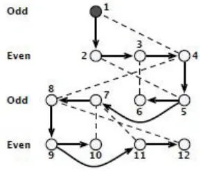
Fig 4: Position of nodes at different layers
The layering phase for the example network in Figure 3 is shown in Figure 4 for the colored tree link disjoint case.
C. Selection of red and blue trees
The third part is to select the red (left) and blue (right) forwarding nodes, denoted by lfn and rfn, respectively. Irrespective of how the layering of nodes approach is performed, the selection method for the left and right forwarding nodes is the same. In the layering part, place the drain node at the first layer (ODD). Arrange the following nodes in the even layer in the increasing order of their DFS values from left node to right node. At the even layer the low point path is in the right direction and at the ODD layer it is in the left direction. Based on this arrangements, a node has two options for its forwarding nodes first is DFS parent node and second is generalized lowpoint neighbor (GLPN) node [8].
If node µ is in the EVEN layer, then
lfn(µ) = p(µ) and rfn(µ) = glpn(µ)
If node µ is in the ODD layer, then
lfn(µ) = glpn(µ) and rfn(µ) = p(µ)
[image:5.612.373.518.252.380.2]International Journal of Emerging Technology and Advanced Engineering
Website: www.ijetae.com (ISSN 2250-2459,ISO 9001:2008 Certified Journal, Volume 3, Issue 7, July 2013)
94
A. Red (Left) Tree B. Blue (Right) Tree Fig 5: Red (Left) and Blue (Right) trees obtained from the layered
structure
The paths from any node to the drain node on the two trees are only link disjoint, even if the network is two nodes connected. For example, the paths from node 8 to the drain node are, on red tree: 8-4-3-2-1 and on blue: 8-7-5-4-1, with a common node 4 for both the tree.
3.3 Multiple Drain Nodes and Data Fusion Technique
The colored tree procedure described in this section for link failure is used with data fusion approach and it is extended to generate colored trees when there are multiple drain nodes. The objective of the multiple drain node is to find two disjoint paths to two distinct drain nodes in the network. Compare to other pair of drain nodes, the average length of the two paths of chosen pair of drain nodes should be shortest.
To generate trees to disjoint drains using colored algorithm, the three parts of the algorithm will be same except that the drain nodes are assumed to be connected with a virtual drain node v. The virtual node takes its DFS index value as 0, so that all other drain nodes will have their GLPV as 0. By assuming that the colored tree procedure is initiated from one of the drain nodes (initialized to 1), the trees obtained provide paths to two distinct drain nodes.
Data fusion technique is to be added to colored tree procedure to improve the performance of red and blue tree. Data fusion is the process of integrating multiple data and knowledge representing the real-world object into a consistent, useful, and accurate representation. There will be a less chance of overload at the nodes and data will be forwarded to another node in consistent and accurate way, it will reduce the possibility of failure due to overload at node. By using a colored algorithm for multiple drain nodes, average path length will be reduce compare to single drain node.
3.4. Data Flow Architecture
Data flow architecture represents graphical view of flow of data through an information system and modelling its process aspects.
[image:6.612.65.273.137.251.2]This are a preliminary step used to create an overview of the proposed system which can be elaborated later. Data flow architecture (Data Flow Diagram) can also be used for the visualization of data processing of system.
Fig 6: DFD Level 0 Diagram
DFD Level 0
This is called as Fundamental level DFD for proposed system. It represents the entire system element as a single bubble with input and output. Packets are forwarded to its destination node; upon failure occur colored tree algorithm will recover the link failures by producing red and blue trees.
DFD Level 1
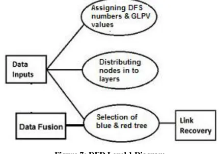
[image:6.612.330.555.187.295.2]This is called as Advanced level DFD for proposed system. It represents the entire process activities in the core system. And inputs and outputs in DFD Level 0 will remain same for DFD level 1. Colored tree algorithm will recover links by processing its three steps and generate red and blue tree with integrated data fusion technique to improve overall system performance.
Figure 7: DFD Level 1 Diagram
3.5 Turing Machine
[image:6.612.336.551.496.647.2]International Journal of Emerging Technology and Advanced Engineering
Website: www.ijetae.com (ISSN 2250-2459,ISO 9001:2008 Certified Journal, Volume 3, Issue 7, July 2013)
95
[image:7.612.329.556.112.319.2]Fig 8: State Diagram
In State 2 recovery procedure is applied with data fusion technique to recover from failure and to improve system performance. It generate to trees red and blue tree. In state 3 packets are forwarded using red tree links and if red forwarding links failed then packets are forwarded to state 4. In state 4 packets are forwarded using blue tree.
IV. RESULTS AND DISSCUSSION
Recovery path length from dual link failure in IP Network, using the colored tree approach, described in section 3 is lesser than that of the path augmentation approach.
[image:7.612.57.282.135.349.2]The colored tree approach reduces the number of nodes that lose both the paths less than two link failures compared to the path augmentation approaches and message overhead at nodes can be reduced by using data fusion approach.
Fig 9: Packet Structure
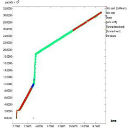
The graph in fig.9 display the number of packets forwarded and dropped with the number of link failed in network containing multiple drain nodes. Fig.10 display the packets sent and received in multi drain network with dual link failure.
The colored tree algorithm finds two disjoint paths such that the average path length of a node to its pair of drain nodes is smaller than compare to the average path length to any other pair of drain nodes.
[image:7.612.327.553.434.659.2]International Journal of Emerging Technology and Advanced Engineering
Website: www.ijetae.com (ISSN 2250-2459,ISO 9001:2008 Certified Journal, Volume 3, Issue 7, July 2013)
96
Colored tree algorithm with data fusion process will improve overall system performance and it reduces the chance of failure due to traffic overload at nodes because it forwards data in accurate and consistent way.
V. CONCLUSION
Recovery from dual link failure in a multiple drain network using colored tree algorithm construct two trees red and blue such that two paths for any node to the drain node d on their respective trees are node or link disjoint. It is linear with the number of nodes in the IP Network. When link or node failure occurs in IP network, it computes the CTs with minimum disruption to the existing network architecture. Colored tree approach with data fusion technique forward the data in consistent and accurate way and improve system performance. Dual link recovery approach in multi-drain network finds two disjoint paths to two distinct drain nodes in the network. By using multiple drains node network average path length is reduced, when every node finds two disjoint paths to two distinct drain nodes.
Acknowledgement
With immense pleasure, I am presenting the paper as part of the curriculum of the M.E. Computer Engineering. I wish to thank all the people who gave me an unending support right from the idea was conceived. Inspiration and guidance are invaluable in every aspect of life especially in the field of academics, which I have received from our respected Mr. A. J. Patankar: Head of Computer Department, Mrs. M. A. Potey: Term work Coordinator, Ms. S. S. Pawar: PG Coordinator and Ms. Deepali Gothwal: Guide. I also acknowledge the research work done by all the researchers in this field.
REFERENCES
[1] Shrinivasa Kini, Srinivasan Ramasubramanian, “Fast Recovery From Dual-Link or Single-Node Failures in IP Networks Using Tunneling”, IEEE 2010.
[2] Amund Kvalbein, Audun Fosselie Hansen, “Multiple Routing Configurations for Fast IP Network Recovery”, University of Oslo, 1371 Oslo, IEEE 2009.
[3] Shrinivasa Kini, Srinivasan Ramasubramanian, “Fast Recovery from Dual Link Failures in IP Networks”, University of Arizona, Tucson, AZ, USA, IEEE 2009.
[4] Athina Markopoulou, Gianluca Iannaccone, “Characterization of Failures in an Operational IP Backbone Network”, IEEE 2008. [5] Kang Xi and H. Jonathan Chao, “IP Fast Reroute for Double-Link
Failure Recovery”, Polytechnic Institute of New York University, Brooklyn, IEEE 2009.
[6] Audun Fosselie Hansen, Olav Lysne, and Stein Gjessing, “Fast Proactive Recovery from Concurrent Failures”, Simula Research Laboratory, Oslo, Norway, IEEE 2007.
[7] Serhat Nazim Avci, Xiaodan Hu, and Ender Ayanoglu, “Hitless Recovery from Link Failures in Networks with Arbitrary Topology”,Department of Electrical Engineering and Computer Science University of California, Irvine.
[8] Giridhar Jayavelu, Srinivasan Ramasubramanian, and Ossama Younis, “Maintaining Colored Trees for Disjoint Multipath Routing Under Node Failures”, IEEE 2009.
[9] Michael Menth, Ruediger Martin, and Ender Ayanoglu, “Network Resilience through Multi-Topology Routing”, Institute of Computer Science, University of W¨urzburg.
[10] András Császár , TrafficLab, “IP Fast ReRoute: Lightweight Not-Via without Additional Addresses”, Ericsson Research , Laborc utca. [11] P´eter Szil´agyi, Zolt´an T´oth, “Design, Implementation and Evaluation of an IP Fast ReRoute Prototype”, Budapest University of Technology and Economics, June 2008.
[12] Adrian S.-W. Tam Kang Xi H. Jonathan Chao, “Design, Implementation and Evaluation of an IP Fast ReRoute Prototype”, Budapest University of Technology and Economics, June 2008. [13] Adrian S.-W. Tam Kang Xi H. Jonathan Chao, “A Fast Reroute
Scheme for IP Multicast”, Department of Electrical and Computer Engineering Polytechnic Institute of New York University, IEEE 2009.
[14] Mario Pickavet, Piet Demeester, Didier Colle, “Recovery in Multilayer Optical Networks”, Department of Information Technology (INTEC), Ghent University, Belgium, IEEE 2006. [15] S. Ramasubramanian, M. Harkara, and M. Krunz, “Distributed linear
time construction of colored trees for disjoint multipath routing”, Coimbra, Portugal, May 2006.
[16] Shu-wen PAN, “Fast IP Network Recovery Using Imperative-Forwarding-Path Routing”, State Lab of Switching and Networking Technology Beijing University of Posts and Telecommunications Beijing, China, IEEE 2009.
[17] Kang Xi, H. Jonathan Chao and Chaoyi Guo, “Recovery from Shared Risk Link Group Failures using IP Fast Reroute”, Polytechnic Institute of New York University, Brooklyn, New York 11201, IEEE 2010.