International Journal of Emerging Technology and Advanced Engineering
Website: www.ijetae.com (ISSN 2250-2459,ISO 9001:2008 Certified Journal, Volume 3, Issue 7, July 2013)
228
Implementation of communication using Cyclic Redundancy
Check
Jyoti Wadhwani
1, Prof. Nitin Narkhede
21
Department of Electronics Engineering RCOEM, Nagpur,
2Department of Electronics & Telecommunication Engineering, RCOEM, Nagpur
Abstract- Cyclic redundancy checking is a method of checking for errors in data that has been transmitted on a communications link. The Cyclic Redundancy Check (CRC) is an efficient technique for detecting errors during digital data transmissions between a source and a destination. It is designed to be fast and easy to implement in a hardware by using logic XOR (exclusive OR) gates and shifters. The algorithm provides very good protection from burst errors, which are typical for transmission lines. Thanks to easy implementation, it is useful for error detection but cannot safely rely on data integrity verification.
This paper describes the mathematical basis behind CRC in an intuitive fashion and then explains Algorithm for the serial CRC generating and checking at both transmitter and receiver side. This includes analyzing various types of error during transmission.
Keywords- Checksum, Codeword, CRC standards, Generator polynomial, Syndrome.
I. INTRODUCTION
Every modern communication protocols uses one or more error-detection algorithms to achieve reliable communication between source and destination. CRC is by far the most popular. The sender and receiver agree on a certain fixed polynomial called the generator polynomial.CRC properties are defined by length and coefficients of the generator polynomial.. The protocol specification generally defines CRC in hexadecimal or polynomial notation. Table 1 shows the generator polynomials used by some common CRC standards. The ―Hex‖ column of the Table shows the hexadecimal representation of the generator polynomial; the most significant bit is omitted, as it is always 1.
TABLE 1.
GENERATOR POLYNOMIAL OF SOME CRC CODES[5]
Comman Name
r
Generotor
Polynomial Hex
CRC-12 12 x 12 + x 11 + x 3 + x2+x+1 80F
CRC-16 16 x 16 + x 15 + x2 + 1 8005
CRC-CCITT
16 X16 + x12+ x5 +1 1021
CRC-32 32 X32+x26+x23+x22+x16+ x12+x11+x10+x8+x7 +x5+x4+x2+1
04C11DB7
The CRC standards differ in ways other than the choice of generating polynomial. Most initialize by assuming that the message has been preceded by certain nonzero bits, others do no such initialization. Most transmit the bits within a byte least significant bit first, some most significant bit first. Most append the checksum least significant byte first, others most significant byte first. Some complement the checksum.
International Journal of Emerging Technology and Advanced Engineering
Website: www.ijetae.com (ISSN 2250-2459,ISO 9001:2008 Certified Journal, Volume 3, Issue 7, July 2013) Data Interface), the IEEE-802 LAN/MAN standard, and
in some DOD applications.
This application note describes the Cyclic Redundancy Check (CRC) theory and implementation. This application describes the implementation of the CRC-CCITT polynomial.
II. WORKING OF CRC
The CRC is based on polynomial arithmetic, in particular, on computing the remainder of dividing one polynomial in GF(2) (Galois field with two elements) by another. It is a little like treating the message as a very large binary number, and computing the remainder on dividing it by a fairly large prime number such as 216-4. Intuitively, one would expect this to give a reliable checksum.
A polynomial in GF(2) is a polynomial in a single variable x whose coefficients are 0 or 1. Addition and subtraction are done modulo 2—that is, they are both the same as the exclusive OR operator.
The CRC method treats the message as a polynomial in GF(2). For example, the message 11001001, where the order of transmission is from left to right(110…) is treated as a representation of the polynomial x7 + x6 + x3 + 1. The
sender and receiver agree on a certain fixed polynomial called the generator polynomial G(x).
The CRC-CCITT generator polynomial is shown in Table 1. The polynomial can be translated into a binary value, For example, the CRC-CCITT polynomial translates to 10001000000100001b. All coefficients, like x12 or x5, are represented by a logical 1 in the binary value.
III. CRCHARDWARE IMPLEMENTATION
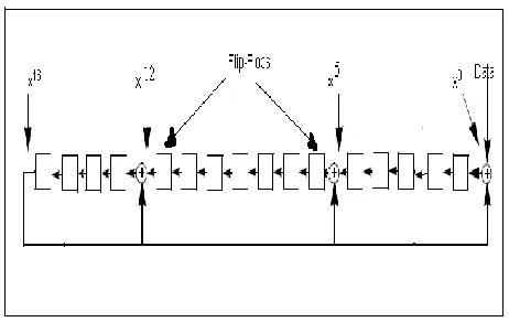
[image:2.612.54.285.532.678.2]Figure 1. HARDWARE CRC-CCITT GENERATOR
The CRC calculation is realized with a shift registers and XOR gates. Figure 1 shows a CRC generator for the CRC-CCITT polynomial. Each bit of the data is shifted into the CRC shift register (Flip-Flops) after being XOR‘ed with the CRC‘s most significant bit.
IV. CRCSOFTWARE IMPLEMENTATION
Following are steps for implementing a CRC in software. The steps for CRC computation are followed at transmitter side and that for CRC Checking are followed at receiver side.
4.1 Steps of CRC computation at transmitter[4]
• To compute an n-bit binary CRC, line the bits representing the input in a row, and position the (n+1)-bit pattern representing the CRC's divisor (called a "generator polynomial") underneath the left-hand end of the row.
•
Start with the message to be encoded: 10001110 = X7 + x 3 + x 2 +x 1
• This is first padded with zeroes corresponding to the bit length n of the CRC. Here is the first calculation for computing a 16-bit CRC:
10001110 0000000000000000 <--- input right padded by 16 bits
10001000000100001 <--- divisor (17 bits) = x16+x12+x5+1
---
000001100001000010000000 <--- result
4.1.1 Three Steps
The divisor is XOR‘ed into the input
Note: in other words, the input bit above each 1-bit in the divisor is toggled
The divisor is then shifted one bit to the right, and the process is repeated until the divisor reaches the right-hand end of the input row. Here is the entire calculation:
• 100011100000000000000000 <--- input right padded by 16 bits
• 10001000000100001 <--- divisor
• 000001100001000010000000 <--- result
• 10001000000100001 <--- divisor
• 0100101000000000100 <--- result
• 10001000000100001 <--- divisor
• --- ---
International Journal of Emerging Technology and Advanced Engineering
Website: www.ijetae.com (ISSN 2250-2459,ISO 9001:2008 Certified Journal, Volume 3, Issue 7, July 2013)
230
• Since the leftmost divisor bit zeroed every input bit it touched, when this process ends the only bits in the input row that can be nonzero are the n bits at the right-hand end of the row. These n bits are the remainder of the division step, and will also be the value of the CRC function called as checksum.
• The validity of a received message can easily be verified by performing the above calculation again, this time with the check value added instead of zeroes.
The remainder should equal zero if there are no detectable errors.
4.2 Steps of CRC Checking at receiver to detect error[4]
• 100011100111000001000110 <--- input right padded by 16 bits
• 10001000000100001 <--- divisor
• 000001100110000011000110 <--- result
• 10001000000100001 <--- divisor
• 10001000000100001 <--- result
• 10001000000100001 <--- divisor
• ---
• 0000000000000000 <---remainder (16 bits)
Algorithm of Software Implementation
Figure 2 shows a basic implementation of CRC-CCITT computation in software. The program initializes the register named ‗poly‘ to binary value of CRC-CCITT generator polynomial equivalent, appends 16 zero bits to the message and checks its MSB bit. If value of MSB is ‗0‘ then data is copied as it is into temporary register r1 otherwise the data is XOR‘ed with the generator polynomial to store the result in the register r1. Then data is left shifted by one bit and same operation is repeated.
At last the result of CRC computation called as checksum is assigned to crc register.
reg [7:0] message;
reg [16:0] poly; // store generator
polynomial
reg[23:0] data_in1;
reg[16:0] r1; // to store intermediate
result
reg [15:0] crc;
// output port to store crc
computation result i.e checksum
integer i; // loop counter
poly = 17'b10001000000100001;
always @ (data_in1, message)
begin
data_in1 = {message,
16'b0000000000000000};
//
append 16 zero bits to the message
if (data_in1[23] == 0)
r1 = data_in1[23:7];
else
r1 = data_in1[23:7] ^
poly[16:0];
for (i = 6; i >=0; i = i-1)
begin
r1 = {r1[15:0], data_in1[i]};
if (r1[16] == 0)
r1 = r1;
else
r1 = r1 ^ poly;
end
[image:3.612.336.550.110.623.2]end
Fig.2. Basic CRC-CCITT Computation algorithm
[image:3.612.60.275.293.401.2]International Journal of Emerging Technology and Advanced Engineering
Website: www.ijetae.com (ISSN 2250-2459,ISO 9001:2008 Certified Journal, Volume 3, Issue 7, July 2013)
reg [
23
:0] codeword;
// Received Message
reg [16:0] poly;
// store same generator
polynomial
reg [15:0] syndrome;
// output port to store
crc checking result i.e syndrome
poly = 17'b10001000000100001;
reg[23:0] data_in1;
reg[16:0] r1;
integer i;
always @ (data_in1, codeword)
begin
data_in1 = codeword; // here we do not
append 16 zero bits
if (data_in1[23] == 0)
r1 = data_in1 [23:7];
else
r1 = data_in1 [23:7] ^ poly [16:0];
for (i = 6; i >= 0; i = i-1)
begin
r1 = {r1 [15:0], data_in1 [i]};
if (r1 [16] == 0)
r1 = r1;
else
r1 = r1 ^ poly;
end
end
Communication using CRC error detection algorithm
[image:4.612.313.551.304.488.2]Fig 4 shows the communication application using CRC as error detection algorithm. The PRNG – Pseudo Random Number Generator Is used to generate 8 bit messages d(x). The Transmitter will perform CRC computation to encode the message by adding checksum value to it. This encoded message is called codeword c(x). The channel is unreliable transmission line which may corrupt the message due to noise, attenuation and interference. The possibly corrupted codeword at the receiver is decoded using CRC checking algorithm. Note that transmitter and receiver agrees on common generator polynomial G(x). The result of CRC checking is called Syndrome s(x) is used to detect error in the received message.
Fig.4. Communication using CRC technique
Detecting and Verifying errors. A cyclic code can be analyzed to find its capabilities by using polynomials.
Message: d(x) Codeword: c(x) Generator: g(x) Syndrome: s(x) Error: e(x)
In this analysis the intention is to find the criteria that must be imposed on the generator, G(x) to detect the type of error [7].
Here, received codeword = c(x) + e(x)
The receiver divides the received codeword by g(x) to get the syndrome. This can be written as:
Received codeword = c(x) + e(x) G(x) G(x) G(x)
The first term does not have remainder.
International Journal of Emerging Technology and Advanced Engineering
Website: www.ijetae.com (ISSN 2250-2459,ISO 9001:2008 Certified Journal, Volume 3, Issue 7, July 2013)
232 1. The first case when e(x) is 0 if there is no error.
2. The second case when e(x) is divisible by G(x). Those errors that are divisible by g(x) are not caught.
3. In a cyclic code, those e(x) errors that are divisible by g(x) are not caught.
V. CONCLUSION
The CRC error correction is mostly used where large data packages are transmitted, for example, in local area networks such as Ethernet.
We designed the serial circuit shown in figure.1 and reported the output of the circuit for a sample division. This is basic implementation of CRC-CCITT in software. This work can be extended to next version which employs table lookup. This is the usual way that CRC-32 is calculated. Although the programs above work one bit at a time, the table lookup method (as usually implemented) works one byte at a time. A table of 256 full-word constants is used.
REFERENCES
[1] Hamed Sheidaeian and Behrouz Zolfaghari,2012, International Journal of Computer Networks & Communications (IJCNC) Vol.4, No.1. PARALLEL COMPUTATION OF CRC USING SPECIAL GENERATOR POLYNOMIALS
[2] Tanenbaum, Andrew S. Computer Networks, Second Edition. Prentice Hall, 1988.
[3] Thomas Schmidt : Microchip Technology Inc., 2000. Microchip AN730, CRC Generating and Checking
[4] Wikipedia, the free encyclopedia. http://en.wikipedia.org/wiki/Cyclic_redundancy_check
[5] Chapter 14. Cyclic Redundancy Check 7/28/09
[6] P. Hlavka, V. Rehak, A. Smrcka, P. Simecek, D. Safranek, and T. Vojnar,2011, supported by the CESNET activity ―Programmable hardware‖. Formal Verification of the CRC Algorithm Properties. [7] An approach for a Standard Polynomial for Cyclic Redundancy
Check.International Journal of Computer Applications (0975 – 8887), December 2011.