International Journal of Emerging Technology and Advanced Engineering
Website: www.ijetae.com (ISSN 2250-2459,ISO 9001:2008 Certified Journal, Volume 3, Issue 6, June 2013)
629
Modeling and Simulation of Three to Nine Phase Using Special
Transformer Connection
B. Somashekar
1, B. Chandrasekhar
2, David Livingston. D
31,3
Lecturer, Dr. TTIT, KGF
2Asst.prof., MITS, Madanapalli
Abstract-- Three phase supply is available in the generating station or grid, were as nine phase supply is required for many industrial applications such as, aerospace, railway and automobile applications. There are different methods in which we can convert 3 to 9 phase using 18-Pulse Converter, Carrier Based PWM Technique, multilevel converter and Multiphase Transformer. The above said methods which are more complicated to design for higher ratings or a pure sine wave will not be obtained or harmonics will be more.
For Multiphase power transmission system multiphase transformers are needed. In the multiphase power transmission and multiphase rectifier systems, the number of phase can be designed and developed in multiples of three. Therefore, the variable speed multiphase drive system considered in the literature are mostly of five, seven, nine, eleven, twelve, and fifteen phase.
So, there is a need to design and develop special transformer which converts from 3 to 9 phase for different arrangement of input and output. Thus, with the proposed technique, a pure nine-phase sine-wave of fixed voltage/current and frequency is obtained, which can be used for RL load and motor testing purposes. Complete design and simulation of the proposed solution is presented. Analytical calculation and simulation results for RL load is presented in the paper. This model can be simulated by using Orcad simulation software and „SIMPOWERSYSTEMS‟ block sets of MATLAB/SIMULINK software.
Keywords— multi winding transformer, multiphase transmission, three-to-nine phase.
Block diagram.
I. INTRODUCTION
THE use of no of phase systems compared to three phase systems has brought about researchers interest.
The application of multiphase systems is explored in electric power generation, transmission and utilization. The research on multiphase generators has recently started. The research on multiphase drive systems has been significantly developed since the beginning of this century due to advancement in semiconductor devices and digital signal processors technologies. It is to be emphasized here that ac/dc/ac converters generally supply the multiphase motors. Thus, the focus of the current research on multiphase electric drives is limited to the modeling and controlling of the power converters. Little effort is being made to develop static multi winding transformation system to change the phase number from three-to-9-phase. An exception is where a new type of transformer is presented, which is three phase-to-nine-phase system. The analysis and design, however, are completely different.
The control methods to test the motor, which are available to lower the current distortion based on application and requirement. The machine parameters obtained using a PWM inverter or any other method may not provide the correct value. Therefore, a pure sine wave supply system is required to feed the motor for better analysis. Accordingly, this paper proposes a special transformer /multi winding transformer connection scheme to obtain a balanced three-to-nine-phase supply with sinusoidal waveforms. The expected application areas of the proposed transformer are the electric power transmission system, power electronic converters, aerospace, railway and automobile applications and the multiphase electric drive system.
The fixed 3-phase voltage and fixed frequency available in grid power supply can be transformed to fixed voltage and fixed frequency 9-phase output supply. By connecting a three phase auto transformer at the input side , we can get variable output voltage .In this paper, the input and output supply can be arranged in the following manners:
International Journal of Emerging Technology and Advanced Engineering
Website: www.ijetae.com (ISSN 2250-2459,ISO 9001:2008 Certified Journal, Volume 3, Issue 6, June 2013)
630
The input being three-phase system the windings are connected in normally were as, the output/secondary side star connection is discussed in the following sections. The nanogon output connection may be derived following a similar approach. Thus, only star input and star output, delta input and star output connection is discussed in the following section.
II. CALCULATION AND WINDING ARRANGEMENT FOR
NINE-PHASE
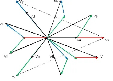
Three separate cores are designed with each of them carrying one primary coil and five secondary coils, are wound. 6 terminals of primaries are connected in an appropriate manner resulting in star/delta connections, and the 30 terminals of secondaries are connected in a different fashion resulting in a star/nonagon output. The connection scheme of secondary windings to obtain input star and output star is illustrated in Figs. 1 and 2 and the corresponding phasor diagram is illustrated in Fig. 3. Similarly for input delta and output star connection is also shown in the fig 4, 5 and 6.
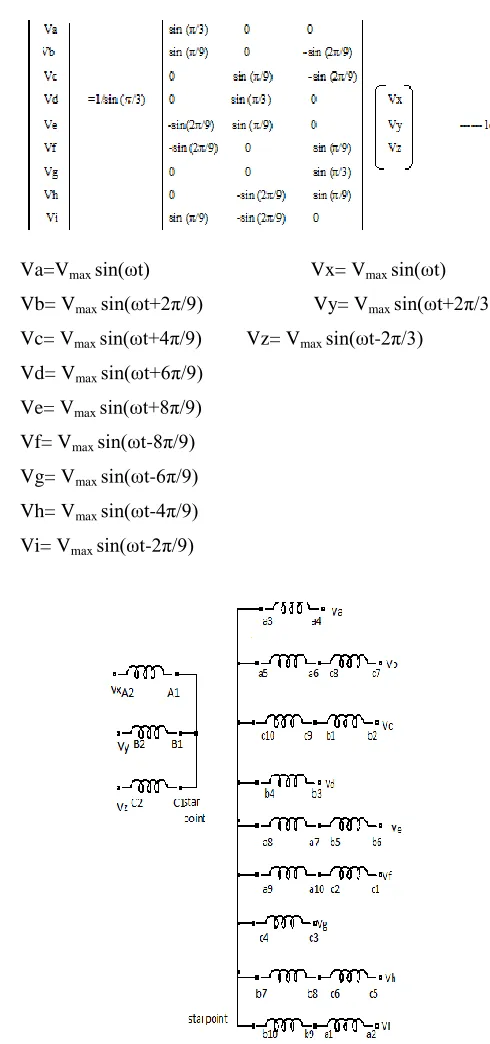
The output phases with requisite phase angles of 360/9 = 40◦ between each phase is obtained using appropriate turn ratios and the phasor equation is given in (1c). Selecting the turn ratio is the key in creating the phase displacement in the output phases. The turn ratios between different phases are given in Table I.
The input phases are represented with letters ―X,‖ ―Y,‖ and ―Z‖ and the output are represented with letters ―a,‖ ―b,‖ ―c,‖ ―d,‖―e,‖ ―f,‖ ―g,‖ ‖h‖ and ―i‖. The mathematical basis for this connection is the basic addition of real and imaginary parts of the vectors. For example, the solution for (1a) gives the turn ratio of phase ―b,‖ (Vb taken as unity)
Vx [cos (2π/9) +j sin (2π/9)]-Vz [cos (π/9) -j sin (π/9)] =1
---1a Equating real and imaginary parts and solving for Vx and Vz ,
[image:2.612.314.559.131.653.2]We get
|Vx | = sin (π/9)/sin (π/3) = 0.394
|Vz | =−sin (2π/9)/sin (π/3)= 0.7422 ---1b
Equation (1c) is the result of solutions of equations like (1a) for other phases.
By simply summing the voltages of two different coils, one output phase is created. It is important to note that the phase ―a‖ output is generated from only one coil namely ―a3a4‖in contrast to other phases which utilizes two coils.
Thus, the voltage rating of ―a3a4‖ coil should be kept to that
of rated phase voltage to obtain balanced and equal voltages
Va=Vmax sin(ωt) Vx= Vmax sin(ωt)
Vb= Vmax sin(ωt+2π/9) Vy= Vmax sin(ωt+2π/3)
Vc= Vmax sin(ωt+4π/9) Vz= Vmax sin(ωt-2π/3)
Vd= Vmax sin(ωt+6π/9)
Ve= Vmax sin(ωt+8π/9)
Vf= Vmax sin(ωt-8π/9)
Vg= Vmax sin(ωt-6π/9)
Vh= Vmax sin(ωt-4π/9)
Vi= Vmax sin(ωt-2π/9)
International Journal of Emerging Technology and Advanced Engineering
Website: www.ijetae.com (ISSN 2250-2459,ISO 9001:2008 Certified Journal, Volume 3, Issue 6, June 2013)
[image:3.612.95.241.137.385.2]631
Fig: II proposed winding arrangement (star-star)
Fig III. Phasor diagram of the proposed transformer connection (star-star).
[image:3.612.390.499.385.601.2]Fig IV Proposed transformer winding connection (delta-star).
[image:3.612.61.274.437.622.2]International Journal of Emerging Technology and Advanced Engineering
Website: www.ijetae.com (ISSN 2250-2459,ISO 9001:2008 Certified Journal, Volume 3, Issue 6, June 2013)
[image:4.612.76.264.142.276.2]632
[image:4.612.327.558.152.345.2]Fig VI Phasor diagram of the proposed transformer connection (delta-star).
TABLE I
TURN RATIO SECONDARY TURNS (N2 ) TO PRIMARY (A1A2) TURNS (N1 )
Name of the winding
Turns ratio N2/N1
Name of the winding
Turns ratio N2/N1
Name of the winding
Turns ratio N2/N1 a1a2 0.394 b1b2 0.394 c1c2 0.394 a3a4 1.000 b3b4 1.000 c3c4 1.000 a5a6 0.394 b5b6 0.394 c5c6 0.394 a7a8 0.7422 b7b8 0.7422 c7c8 0.7422 a9a10 0.7422 b9b10 0.7422 c9c10 0.7422
Where the three-phase voltages (line-to-neutral) are defined as Vj = Vmax sin (ωt - nπ/3)
j = x, y, z, and n = 0, 2, 4, respectively, (2)
Vk = Vmax sin (ωt – nπ/9),
k = a, b, c, d, e, f, g, h, i and n = 0, 2, 4, 6, 8, 10, 12, 14, 16 respectively. (3)
Using (1c), a nine -phase output can be created from a three phase input supply.
Since a transformer works as a two-port network, the reverse connection is also possible, To obtain three-phase outputs from a nine-phase input supply, following relations hold good
A general expression for an ―n‖ phase system is derived and shown in (4)
Vr = [(−1)aVx sin(θ) + (−1)bVy sin(φ) + (−1)cVz sin(γ)] (4)
Where r=phase no 1,2,3………n;
Fig VII. General Phasor diagram for three-phase system from “n” phase system.
Similarly, from Fig. IV, we derived one of the general expressions for three-phase system from ―n‖ phase system in for simplicity, we assume Vx = V1; and n = number of
phases in the system.
Vx, Vy, V1, V2, V3. Vl, . . . Vm . . . are phases. Then
Vy =1/sin (2π/n) [sin (2lπ/n-2π/3) Vl+sin (2π/3-2(l-1)π/n)V l+1]
Where l = 2, 3... And (2lπ/n)>(2π/3)>(2(l-1)π/n)
Vz=1/sin (2π/n) [sin (2mπ/n-2π/3) Vm +
sin(2π/3-2(m-1)π/n)V m+1]
Where (2mπ/n)> (2π/3)> (2(m-1) π/n) and m>1
III. LOAD SHARING OF SECONDARY WINDINGS
Let V1*I1 = S1, where V1 and I1 are input phase voltage and current, respectively, and S1 is average per phase input Volt ampere (VA). Also, let V2*I2 =S2, where V2 and I2 are output phase voltage and current, respectively, and S2 is per phase output VA. After neglecting the losses, we have: 3 S1 = 9 S2 . For transformer A: VA of winding a1a2
Sa1a2=[3S1/9sin (π/3)] *Cos (2π/9) Sin (π/9)
Where (2π/9) is the angle between input Vx and output
Vi in which winding a1a2 is connected and sin
(π/9)/sin(π/3) is the turns ratio of secondary winding a1a2 to primary winding A1A2.
[image:4.612.42.298.341.428.2]International Journal of Emerging Technology and Advanced Engineering
Website: www.ijetae.com (ISSN 2250-2459,ISO 9001:2008 Certified Journal, Volume 3, Issue 6, June 2013)
633
Negative signs indicate opposite polarity of connection for that particular winding .The sum of VA of all secondary windings of transformer A is equal to 1.0*S1
Similarly, the VA relationships for transformers B and C are
The sum of VA of all secondary windings of transformer B is equal to 1* S1,
The sum of VA of all secondary windings of transformer C is equal to 1.0*S1.
The sum of VA of all three transformers
= 1.0 * S1 + 1.0 * S1 + 1.0 * S1 = 3*S1.
From the analysis all the three transformers share equal load.
After complete study of load mismatch, it was found that all systems which are multiple of ―3,‖ i.e., 6, 9, 12, etc., have zero mismatch whereas 5-phase and 10-phase systems have a mismatch of 5.6%, and 7-phase, 14-phase systems have mismatch of 2.3%, but a 4-phase system has highest mismatch of 50%.
As no of phase increases, especially in prime numbered systems, the mismatch decreases such as in 19-phase system the mismatch is 0.325%.
The load mismatch in Transformer ―A,‖ which is connected to input phase ―X,‖ is shown in FigVIII
IV. SIMULATION RESULTS
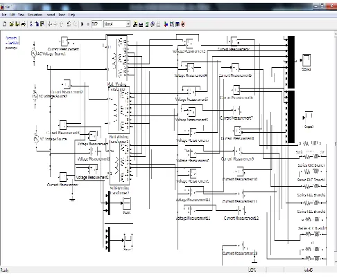
The designed transformer is at first simulated using ―Sim-Power System‖ block sets of the MATLAB/Simulink software.
From sim-power system block library, multi winding block is chosen and the correct turn ratios are set in the dialog box and the simulation is run. Turn ratios are given in Table I.
The resulting input and output voltage waveforms are given in Fig 10 to 14 for star-star and delta star. It is seen that the output is a balanced nine phase supply for a balanced three-phase input. The output will be unbalanced if the input is unbalanced. Individual output phases are also shown along with their respective input voltages and equations.
International Journal of Emerging Technology and Advanced Engineering
Website: www.ijetae.com (ISSN 2250-2459,ISO 9001:2008 Certified Journal, Volume 3, Issue 6, June 2013)
634
[image:6.612.319.576.122.710.2]Fig IX shows the simulation circuit for star-star connection
Fig :X shows the input voltage and current wave forms
Fig XI shows the output voltage and current waveforms
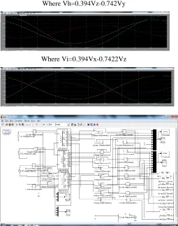
Individual output phases are, also, shown along with their respective input voltages.
Where Va=Vx,
Where Vb=0.394Vx-0.7422Vz
Where Vc= 0.394Vy-0.7422Vz
Where Vd=Vy
Where Ve=0.394Vy-0.7422Vx
Where Vf=0.394Vz-0.7422Vx
[image:6.612.59.302.133.334.2]International Journal of Emerging Technology and Advanced Engineering
Website: www.ijetae.com (ISSN 2250-2459,ISO 9001:2008 Certified Journal, Volume 3, Issue 6, June 2013)
635
Where Vh=0.394Vz-0.742Vy
[image:7.612.48.303.136.459.2]Where Vi=0.394Vx-0.7422Vz
[image:7.612.334.554.433.540.2]Fig XII shows the simulation circuit for delta- star connection
Fig XIII shows the input voltage and current of delta –star
Fig XIV shows the output voltage and current
V. FFTANALYSIS
Fourier analysis is the process of representing a function in terms of sinusoidal components. It is widely employed in many areas of engineering, science, and applied mathematics. It provides information as to what frequency components represent a function.
The FFT analysis gives the THD of the system to that of a fundamental value.
The figure below shows FFT analysis for output voltage signal (star-star)
[image:7.612.335.553.572.671.2]International Journal of Emerging Technology and Advanced Engineering
Website: www.ijetae.com (ISSN 2250-2459,ISO 9001:2008 Certified Journal, Volume 3, Issue 6, June 2013)
636
The table shows THD value for diffent output voltage and current signal for star –star connection
Signal No
%THD Voltage signal
% THD Current signal
1 92.11 0.09
2 92.31 0.08
3 92.30 0.03
4 92.02 0.04
5 91.48 0.08
6 92.33 0.09
7 92.18 0.06
8 92.27 0.02
9 90.87 0.06
The figure below shows FFT analysis for output voltage signal (delta-star)
The figure below shows the FFT anaysis for output current signal(delta-star)
The table shows THD value for diffent output voltage and current signal for delta –star connection
Signal No
%THD Voltage signal
% THD Current signal
1 54.14 0.08
2 103.66 0.09
3 103.44 0.07
4 103.13 0.02
5 98.95 0.05
6 101.13 0.09
7 104.21 0.08
8 103.13 0.04
9 101.797 0.03
VI. CONCLUSION
This paper gives a new method to convert 3 phase to 9 phase using special transformer connection. The winding arrangement and the vector diagram, along with the turn ratios, are given in the table.
The successful implementation of the proposed connection scheme is elaborated upon using simulation of mat-lab software using simpower system blocks. The proposed connection scheme can be used in drives and other multiphase applications.
By using the same method we can also get the nonagon output.
REFERENCES
[1] D. Basic, J. G. Zhu, and G. Boardman, ―Transient performance study of brushless doubly fed twin stator generator,‖ IEEE Trans. EnergyConvers.,vol. 18, no. 3, pp. 400–408, Sep. 2003.
[2] G.K. Singh, ―Self excited induction generator research—A survey,‖ Elect.Power Syst. Res., vol. 69, pp. 107–114, 2004.
[3] O. Ojo and I. E. Davidson, ―PWM-VSI inverter-assisted stand-alone dual stator winding induction generator,‖ IEEE Trans. Energy Convers., vol. 36, no. 6, pp. 1604–1611, Nov./Dec. 2000.
International Journal of Emerging Technology and Advanced Engineering
Website: www.ijetae.com (ISSN 2250-2459,ISO 9001:2008 Certified Journal, Volume 3, Issue 6, June 2013)
637
[5] G. K. Singh, ―Modelling and experimental analysis of a self excited sixphaseinduction generator for stand alone renewable energy generation,‖ Renewable Energy, vol. 33, no. 7, pp. 1605–162, Jul. 2008.
[6] J. R. Stewart and D. D.Wilson, ―High phase order transmission—A feasibilityanalysis—Part-I: Steady state considerations,‖ IEEE Trans. PowerApp. Syst., vol. PAS-97, no. 6, pp. 2300–2307, Nov. 1978.
[7] J.R. Stewart andD.D.Wilson, ―High phase order transmission-Afeasibilityanalysis—Part-II: Over voltages and insulation requirements,‖ IEEETrans. Power Ap. Syst., vol. PAS-97, no. 6, pp. 2308–2317, Nov. 1978.
[8] J. R. Stewart, E. Kallaur, and J. S. Grant, ―Economics of EHV high phaseorder transmission,‖ IEEE Trans. Power App. Syst., vol. -PAS 103, no. 11,pp. 3386–3392, Nov. 1984.
[9] S. N. Tewari, G. K. Singh, and A. B. Saroor, ―Multiphase Power transmissionresearch—A survey,‖ Electr. Power Syst. Res., vol. 24, pp. 207–215,1992.
[10] C. M. Portela andM.C. Tavares, ―Six-phase transmission line-propagation characteristics and new three-phase representation,‖ IEEE Trans. Power Delivery, vol. 18, no. 3, pp. 1470–1483, Jul. 1993.
[11] T. L. Landers, R. J. Richeda, E. Krizanskas, J. R. Stewart, and R. A. Brown, ―High phase order economics: Constructing a new transmission line,‖IEEE Trans. Power Delivery, vol. 13, no. 4, pp. 1521–1526, Oct. 1998.
[12] J. M. Arroyo and A. J. Conejo, ―Optimal response of power generators toenergy, AGC, and reserve pool based markets,‖ IEEE Power Eng. Rev.,vol. 22, no. 4, pp. 76–77, Apr. 2002.
[13] M. A. Abbas, R. Chirsten, and T. M. Jahns, ―Six-phase voltage sourceinverter driven induction motor,‖ IEEE Trans. Ind. Appl., vol. IA-20,no. 5, pp. 1251–1259, Sep./Oct. 1984.
[14] K. N. Pavithran, R. Parimelalagan, and M. R. Krsihnamurthy, ―Studies oninverter fed five-phase induction motor drive,‖ IEEE Trans. Power Elect.,vol. 3, no. 2, pp. 224–235, Apr. 1988.
[15] G. K. Singh, ―Multi-phase induction machine drive research—A survey,‖Electr. Power Syst. Res., vol. 61, pp. 139–147, 2002. [16] R. Bojoi, F. Farina, F. Profumo, and A. Tenconi, ―Dual-three phase
inductionmachine drives control—A survey,‖ IEE J. Trans. Ind. Appl., vol. 126, no. 4, pp. 420–429, 2006.
[17] E. Levi, R. Bojoi, F. Profumo, H. A. Toliyat, and S. Williamson, ―Multiphaseinduction motor drives—A technology status review,‖ IET Electr. Power Appl., vol. 1, no. 4, pp. 489–516, Jul. 2007. [18] E. Levi, ―Multiphase electric machines for variable-speed
applications,‖IEEE Trans Ind. Elect., vol. 55, no. 5, pp. 1893–1909, May 2008.
[19] A. Iqbal and E. Levi, ―Space vector PWMtechniques for sinusoidal outputvoltage generation with a five-phase voltage source inverter,‖ Electr.Power Compon. Syst., vol. 34, no. 2, pp. 119–140, 2006. [20] D. Dujic, M. Jones, and E. Levi, ―Generalised space vector PWMfor
sinusoidaloutput voltage generation with multiphase voltage source inverter,‖Int. J. Ind. Elect. Drives, vol. 1, no. 1, pp. 1–13, 2009. [21] M. J. Duran, F. Salas, and M. R. Arahal, ―Bifurcation analysis of
fivephaseinduction motor drives with third harmonic injection,‖ IEEE Trans.Ind. Elect., vol. 55, no. 5, pp. 2006–2014, May 2008.
[22] M. R. Arahal and M. J. Duran, ―PI tuning of five-phase drives with thirdharmonic injection,‖ Control Engg. Pract., vol. 17, no. 7, pp. 787–797,Jul. 2009.
[23] D. Dujic, M. Jones, and E. Levi, ―Analysis of output current ripple rmsin multiphase drives using space vector approach,‖ IEEE Trans. Power Elect., vol. 24, no. 8, pp. 1926–1938, Aug. 2009.
[24] M. Correa, C. R. da Silva, H. Razik, C. B. Jacobina, and E. da Silva, ―Independent voltage control for series-connected six-and three-phase Induction machines,‖ IEEE Trans. Ind. Appl., vol. 45, no. 4, pp. 1286–1293, Jul./Aug. 2009.
[25] A. Iqbal, S. Moinuddin, M. R. Khan, SK. M. Ahmed, and H. Abu-Rub, ―Anovel three-phase to five-phase transformation using special transformerconnection,‖ IEEE Trans. Power Delivery, vol. 25, no. 3, pp. 1637–1644,Jun. 2010.
[26] A. Iqbal, S. Moinuddin, M. R. Khan, SK. M. Ahmed, and H. Abu-Rub, ―Anovel three-phase to seven-phase transformation using special transformerconnection,‖ IEEE TRANSACTIONS ON ENERGY CONVERSION, VOL. 27, NO. 3, SEPTEMBER 2012. [27] M. H. Rashid, Power Electronics Handbook: Devices, Circuits, and
Applications, 3rd ed. Amsterdam, The Netherlands: Elsevier, 2011. [28] M. Jones, ―A novel concept of a multi-phase multi-motor vector
controlled drive system,‖ Ph.D. dissertation, School Eng., Liverpool John Moores Univ., School Eng., Liverpool, U.K., 2005.
[29] A. Iqbal, ―Modelling and control of series-connected five-phase and sixphase two-motor drive,‖ Ph.D. dissertation, School Eng., Liverpool John Moores Univ., School Eng., Liverpool, U.K., 2006. [30] G. K. Singh, K. B. Yadav, and R. P. Saini, ―Modelling and analysis
of multiphase (six-phase) self-excited induction generator,‖ in Proc. 8th Int.Conf. Electr. Mach. Syst., 2005, pp. 1922–1927.
[31] G. K. Singh, K. B. Yadav, and R. P Sani, ―Capacitive self-excitation in six-phase induction generator for small hydro power—An experimental Investigation,‖ IEEE Conf. Power Electron., Drives Energy Syst. Ind. Growth [CD-ROM], New Delhi, India, Dec. 2006, Paper 5A-20.
[32] M. Jones and E. Levi, ―A literature survey of the state-of-the-art in multiphaseac drives,‖ in Proc. Int. UPEC, Stafford, U.K., 2002, pp. 505–510.
[33] A. Iqbal and E. Levi, ―Space vector modulation schemes for a five-phase voltage source inverter,‖ presented at the Eur. Power Electron. Conf.[CD-ROM], Dresden, Germany, 2005, Paper 0006.pdf. [34] H. M. Ryu, J. H. Kim, and S. K. Sul, ―Analysis of multi-phase space
vector pulse width modulation based on multiple d-q spaces concept,‖ presented at the Int. Conf. Power Electron. Motion Control [CD-ROM], Xian, China, 2004, Paper 2183.pdf.
[35] O. Ojo and G. Dong, ―Generalized discontinuous carrier-based PWM modulation scheme for multi-phase converter-machine systems,‖ presented at the IEEE Ind. Appl. Soc. Annu. Meeting [CD-ROM], Hong Kong, 2005, Paper 38 P3.
International Journal of Emerging Technology and Advanced Engineering
Website: www.ijetae.com (ISSN 2250-2459,ISO 9001:2008 Certified Journal, Volume 3, Issue 6, June 2013)
638
AUTHOR’S PROFILE
SOMASHEKAR. B received B.E degree (Electrical & Electronics Engineering) in Golden Valley Institute of Technology, K.G.F in 1998 under Bangalore University and M. Tech (VLSI & Embedded Systems) from BMS, VTU in 2010.
I am currently working as a lecturer in the Department of Electrical Engineering, Dr.TTIT, KGF. My research areas are Power Systems, Multi Phase supply, VLSI and Power Electronics.
DAVID LIVINGSTON.D received B.E degree from (Electrical & Electronics Engineering) in Dr.Thimmaiah institute of Technology, KGF in 2008 under VTU, Belgaum and pursuing M.Tech (Power Electronics) from KEC, Chittor under JNTUA.
He is currently working as Lecturer in Dr. TTIT, KGF. His research areas include Power Electronics, Digital signal processing.