PERFORMANCE STUDY ON THE EFFECT OF DIFFERENT EXHAUST LENGTH FOR MOTORCYCLE ENGINE
MOHD RIZAN BIN ABDUL
A thesis submitted in partial
fulfilment of the requirement for the award of the Degree of Master of Mechanical Engineering
Faculty of Mechanical and Manufacturing Engineering Universiti Tun Hussein Onn Malaysia
ABSTRACT
This research provides an overview of the performance on the effect of the different exhaust length for motorcycle engine. The research also covers the effect in terms of emissions. The engine used was a motorcycle 125cc 4-stroke gasoline engine. There are two method was used; experiment and simulation. For experiment, load applied to the engine with different lengths of exhaust pipe. The engine speed of this study was controlled in the range of 800 – 1000 rpm. The test engine has been attached to the dynamometer. The engine specifications and measured components of exhaust system were used for modelling and visualization using GT-Power simulation software. The different length of exhaust will be used for the simulation. Brake power, brake mean effective pressure (BMEP) and brake specific fuel consumption (BSFC) of the engine are discussed as the performance of the engine. Besides that carbon dioxide (CO2), carbon monoxide and hydrocarbon (HC) was discussed as the
ABSTRAK
Kajian ini dihasilkan bagi mendapatkan kesan perbezaan panjang ekzos motosikal terhadap kecekapan enjin. Kajian ini juga mengkaji kesan pencemaran yang terhasil daripada ketiga-tiga jenis ekzos. Enjin yang digunakan ialah enjin motosikal empat lejang dengan kuasa 125cc. Terdapat dua kaedah yang digunakan iaitu secara eksperimen dan simulasi. Bagi eksperimen, beban berbeza dikenakan pada enjin dengan pemasangan saiz ekzos yang berbeza. Kelajuan enjin dikawal pada keadaan 800 – 1000 putaran per minit. Enjin disambungkan dengan dynamometer. Bagi proses simulasi, spesifikasi dan saiz komponen bagi sistem ekzos dimasukkan ke dalam perisian GT-Power. Tiga jenis ekzos dengan panjang berbeza digunakan di dalam proses simulasi. Brake power (BP), brake mean effective pressure (BMEP) dan brake specific fuel consumption (BSFC) yang terhasil daripada keputusan eksperimen dan simulasi pada enjin merupakan elemen yang dikaji bagi menilai tahap kecekapan enjin manakala karbon dioksida (CO2), karbon monoksida and
CONTENTS
TITLE i
DECLARATION ii
DEDICATION iii
ACKNOWLEDGEMENT iv
ABSTRACT v
ABSTRAK vi
CONTENTS vii - ix
LIST OF TABLES x
LIST OF FIGURES xi - xiii
LIST OF SYMBOLS AND
ABBREVIATIONS
xiv
LIST OF APPENDICES xv
CHAPTER 1 INTRODUCTION
1.1 Background of study 1.2 Problem statement 1.3 Objectives
1.4 Scopes of study 1.5 Significant of study
CHAPTER 2 LITERATURE RIVIEW 2.0 Literature review 2.1 Stroke system 2.2 Exhaust stroke 2.3 Exhaust component
2.3.1 Exhaust manifolds or EKE 2.3.2 Catalytic converter
2.3.3. Mufflers 2.4 Exhaust system
2.5 Types of exhaust systems. 2.5.1 Single exit pipe 2.5.2 Dual rear exit
2.5.3 Opposite dual exhaust 2.5.4 Dual side exhaust
2.5.5 High performance exhaust systems 2.6 Performance exhaust analysis
2.7 Motorcycle engine 2.8 GT Power
2.9 Dynamometer
2.10 Pollution of gasoline engine
3 4 4-5 5 5-6 6 7 7-8 8 8-9 9 9-10 10 10 11-14 14-15 15-17 17-18 19-21
CHAPTER 3 METHODOLOGY
3.0 Methodology
3.1 Engine selection and exhaust measurement 3.2 Simulation setup
3.3 Experiment setup 3.4 Performance parameters
22-23 24-25 25-29 30-34 35-36
CHAPTER 4 RESULTS AND DISCUSSIONS
4.1 Engine performance by simulation investigation
4.1.1 Brake Power
4.1.2 Brake Mean Effective Pressure 4.1.3 Brake Specific Fuel Consumption 4.2 Exhaust emissions by simulation investigation
4.2.1 Carbon Dioxide 4.2.2 Carbon Monoxide 4.2.3 Hydrocarbon
4.3 Engine performance by experimental study 4.3.1 Brake Power
4.3.2 Brake Mean Effective Pressure 4.3.3 Brake Specific Fuel Consumption 4.4 Exhaust emissions by experimental study 4.4.1 Carbon Dioxide
4.4.2 Carbon Monoxide 4.4.3 Hydrocarbon 37 38 39 40 41 41-42 42-43 43-44 44 44-45 45-46 46-47 47 47-48 49 50
CHAPTER 5 CONCLUSION AND RECOMENDATIONS 5.1 Conclusion
5.2 Recommendations
51-52 52
REFERENCES 53-56
LIST OF TABLES
3.1
3.2 3.3
The specification of 125cc 4-Stroke Motorcycle Gasoline engine.
The different length of exhaust
Different exhaust length setting in GT Power
24
LIST OF FIGURES
2.1 The example of exhaust manifold 6
2.2 Details of three way catalytic converter 6
2.3
2.4
2.5
The variation in heat carried away by exhaust gases in % with backpressure on engine for different load conditions using exhaust diffuser system
Result for varition of backpressure with engine speed
The different speed effect to the brake power
12
13
13
2.6 The different speed effect to brake specific fuel consumption (BSFC)
14
2.7 The basic schematic of engine model in GT Power
16
2.8 Systems model in the simulation modeling 17
2.9 Eddy Current Dynanometer 18
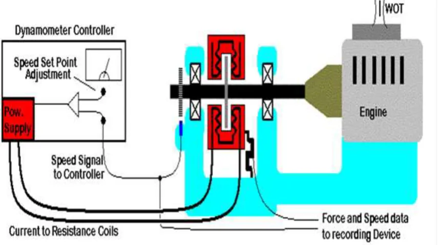
2.10 Schematic of a Speed Controlled test of engine 18 2.11 Relation between exhaust emissions and
air/fuelratio for Gasoline Engines
20
2.12 Estimated annual air pollutant emission loads of HC, CO, PM, NO2 and SO2 from motor
vehicles for 2009 and 2010
20
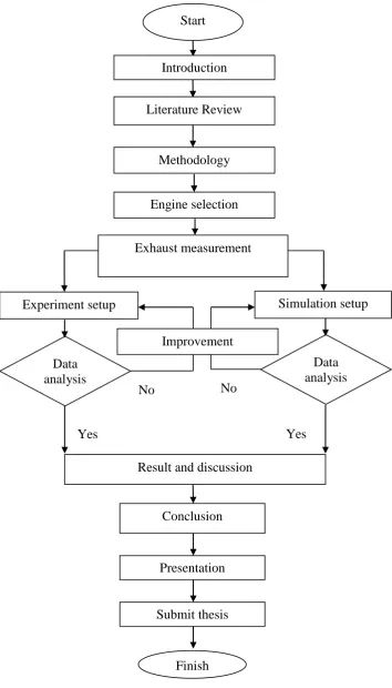
3.1 Flowchart for research process 23
3.2 Component development in GT Power 26
3.4 The exhaust component parameter settings in GT Power
27
3.5 Engine speed setting in GT Power 28
3.6 Simulation process in GT Power 28
3.7 Simulation results using graphs in GT Power 29 3.8 Simulation results using the table in GT Power 29 3.9 3.10 3.11 3.12 3.13 3.14 3.15 3.16 4.1 4.2 4.3 4.4 4.5 4.6 4.7 4.8 4.9 4.10
The schematic drawings for the experiment testing
Dynamometer Blower
Emission Analyser
Ono Sokki Mass Flow Meter Standard length of exhaust Short length of exhaust Long length of exhaust
The result for Brake Power in simulation The result Brake Mean Effective Pressure in simulation
The results of Brake Specific Fuel Consumption (BSFC) in simulation
The result for Carbon Dioxide in simulation The results for Carbon Monoxide in simulation The results of the simulation for Hydrocarbons for three types of exhaust at different RPM
The result for Brake power in experiment The result for Brake mean effective power in experiment
The result for Brake specific fuel consumption in experiment
The result for CO2 in experiment
4.11 4.12
The result for CO in experiment
The result for Hydrocarbon in experiment
LIST OF SYMBOLS AND ABBREVIATIONS
ṁ - Fuel Flow Rate nc - Number Of Cylinder
Vd - Engine efficient volume
B - Size Of Bore
BMEP - Brake Mean Effective Pressure BP - Brake Power
BSFC - Brake Specific Fuel Consumption CO - Carbon Monoxide
CO2 - Carbon Dioxide
HC - Hydrocarbon L - Length Of Stroke N - Shaft Speed
O2 - Oxygen
PPM - Parts per million RPM - Rotation per minute
T - Torque
LIST OF APPENDICES
APPENDIX TITLE PAGES
A B
Gannt Chart PS 1 Gannt Chart PS 2
CHAPTER 1
INTRODUCTION
1.1 Background of study
Exhaust system is a part of vehicle components. Nowadays, there are a few types of exhaust system that already developed to provide a specific user’s demand. Mohiuddin, Rahamn, & Dzaidin, (2007) stated, the exhaust. According to Mohiuddin et al., (2007), a well-designed exhaust system is one of the cheapest ways of increasing engine efficiency, and therefore increasing engine power. Dynamometer is a device for measuring force, torque, or power. Han-chi, Hong-wu, & Yi-jie, (2012) reported, GT-Power is the industry standard engine simulation tool, used by all leading engine and vehicle makers and their supplier. Many assumptions and simplifications were made to the system in order to complete the model. Then, data will be recorded for analysis and discussion.
1.2 Problem statement
exhaust process, it’s disrupted the level of efficiency of the engine. Therefore the size (length) of the exhaust is very important in ensuring the level of efficiency of the engine can achieve the maximum level.
1.3 Objectives
The objectives of this study are:
i. To determine the optimum length of exhaust manifold for achieving good performance using GT-Power software.
ii. To investigate the effect of different lengths of exhaust manifold to the performances of motorcycle engine.
1.4 Scopes of study
To ensure that the studies will be done accordingly, all the scopes related to the study must be focused on. Here is a list of the scopes of study:
i. This research focused on motorcycle engine with capacity of 125cc. ii. Simulation and analysis study were carried out using GT-Power software. iii. The engine was operated at steady state condition with variable
dynamometer loads for experimental investigation.
1.5 Significant of study
CHAPTER 2
LITERATURE REVIEW
One of the important components in a vehicle's is exhaust system. The exhaust system is designed to collect the exhaust gases from the engine cylinders, direct them to the muffler, where exhaust noise is reduced, and discharge them into the atmosphere. In addition, exhaust gases may be used to drive a turbocharger for improved air induction for combustion. The exhaust may also be used to eject dirt and dust from the air cleaner into the atmosphere. The exhaust is a component on the burning waste before the engine is released into the atmosphere. Combustion wastes discharged after-stroke exhaust complete operating in the engine.
2.1 Stroke System
According to Mat & Salim (2011) studied, combustion is one of the chemical reactions that always happen in around the world especially in automotive vehicle. Today, different types of internal combustion engines are the most common used on vehicles such as cars, buses, trucks and motorcycles is the engine four-stroke, whether gasoline engines or diesel engines. One-stroke refers to the movement of the piston from the top to the fixed point fixed point or vice versa then the four-stroke engine gets its name from four-four-stroke each perform a function special entries, compression, procurement authority and the removal of the exhaust gas.
4-stroke engine, also known as Otto cycle engine start patented by Eric b. Davidson and Felice Matteucci in 1854, followed by the first prototype in 1860. They also conceptualized by French engineer, Alphonse Beau de Rochas in 1862 and independently, by German engineer Nicolaus Otto in 1876. Power cycle consists of compression, the addition of heat, expansion and removal of heat, represented by characters four strokes, or the movement of the piston in the cylinder fluctuation. Following are the order of stroke system for four-stroke gasoline and diesel engine :
i. Intake stroke ii. Compression stroke iii. Combustion/power stroke iv. Exhaust stroke
2.2 Exhaust stroke
the exhaust valve. Pilkrabek (2003) also explained, the cylinder is still filled with exhaust gases at the exhaust manifold pressure of about one atmosphere. The piston travel from the bottom dead center until top dead center and the pushed out the exhaust gases. This process call exhaust stroke.
2.3 Exhaust component
The main Components in engine exhaust system are as following sub-sections.
2.3.1 Exhaust manifolds or EKE
Figure 2.1: The example of exhaust manifold (Reddy & Reddy, 2012)
2.3.2 Catalytic converter
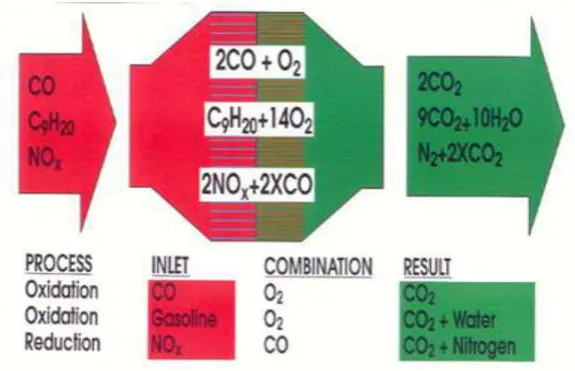
Reddy & Reddy (2012) explained, it is a device used for convert harmful gases like carbon monoxide (CO), nitrogen oxides (NO) into harmless gases like CO2 and N2
etc., In present days "three-way" (oxidation-reduction) catalytic converters are widely used on diesel engines to reduce hydrocarbon and carbon monoxide emissions. Figures 2.2 shows details of three way catalytic converter.
[image:18.595.173.461.521.706.2]Reddy & Reddy (2012) defined, the muffler is defined as a device for reducing the amount of noise emitted by a machine. To reduce the exhaust noise, the engine exhaust is connected via exhaust pipe to silencer called muffler. The various types of mufflers used in automobiles are:
i. Baffle type ii. Resonance type
iii. Wave cancellation type
iv. Combined resonance and absorber type v. Absorber type mufflers.
Purpose of Muffler:
i. to reduce the amount of noise emitted by a vehicle. ii. use neat technology to cancel out the noise.
iii. installed along the exhaust pipe as a part of the exhaust system of an I.C. engine to reduce its exhaust noise.
iv. To reduces exhaust noise by dampening the pulsations in the exhaust gases and allowing them to expand slowly.
v. usually made of sheet steel, coated with aluminum to reduce corrosion. Some are made of stainless steel.
2.4 Exhaust System
same manner, although there are many different variations and configurations. All types of vehicles, not just cars, have exhaust systems, and may vary slightly.
According to Ahmet Selamet (1999) explained, a new automobile exhaust system
reduces pollution and boosts engine power at the same time. The single design takes the place of multiple parts in the standard auto exhaust assembly, including the manifold, muffler and catalytic converter. Rynne (1994) clarify; the effect of vehicle exhausts system components on performance and noise in firing spark-ignition engine. Abraham JA (2010) stated, noise is an unwanted sound at amplitude which causes annoyance or interferes with communication. Noise has been known as menace that can cause a several serious health effect. According to Hultgren, (2011), the noise maybe generated by aerodynamic effects or due to forces that result from combustion process or may result from mechanical excitation of rotating or reciprocating engine components.
2.5 Types of Exhaust Systems
Nowadays, many type of exhaust produce to make various of exhaust. Different design of exhaust also want to increase performance of engine and reduce emission. Types of exhaust system below:
2.5.1 Single Exit Pipe
2.5.2 Dual Rear Exit
Dual Side Exhaust system has nearly the same design and location, as the single pipe exhaust system. The one and major difference is in the quantity of exit pipes. This type of exhaust systems is constructed with two pipes. Both pipes are located near each other on the same side of the vehicle behind the rear passenger's side. Depending on the diameter of the exit pipes the sound of system's performance may vary. When the diameter is smaller, the deeper sound will be produced. A dual side exit exhaust has 2 pipes located on the same part of the vehicle. If you want a louder sound than the single side exit, this is your best bet. It also provides less restriction on your car's exhaust system. The canister exhaust for this type is often larger than the actual size of the cylinder. With this type of exhaust, the pipes are located beneath the bumper and are not bent around the rear wheels. It is often said that a dual rear exit exhaust looks better than the other types.
2.5.3 Opposite Dual Exhaust
terms of the location of the pipes. It provides the same sound and performance. For this exhaust, the two pipes wrap around on each side of the rear wheels. This type of exhaust is suitable for trucks or cars that often tow other vehicles. The downpipe and the exhaust pipe are generally made from stainless steel.
2.5.4 Dual Side Exhaust
Opposite Dual Exhaust is also called extreme dual exit exhaust. It is a variation of the dual rear exhaust system. Opposite dual exhaust is mainly used on vehicles that tow heavy cargo. In order to improve the filtering process, the length of the pipes is increased and they are bent around the wheels. This construction makes it possible to decrease the residue that is released on the object that is towed. Besides the length and location of the pipes there is no major difference towards the other exhaust systems.
2.5.5 High Performance Exhaust Systems
This study focus on performance of motorcycle engine when the length of exhaust modified. According to Obodeh & Ogbor (2009) studied, engine performance is strongly dependent on gas dynamic phenomena in intake and exhaust systems. Han-chi, Hong-wu, & Yi-jie (2012) explained, performance of engine can be studied by analyzing the mass and energy flows between individual engine components and the heat and work transfers within each component.
To get better result for analysis exhaust, different condition of engine operate must be consider. From different condition the exhaust system can be develop with maximum utilization of available energy at the exhaust. Patil et al. (2014) stated, design of each device should offer minimum pressure across the device, so that it should not adversely affect the engine performance. In the exhaust stroke, the piston moves from bottom dead center (BDC) to the top dead center (TDC), pressure rises and gases pushed into exhaust pipe. Then, the power required to drive exhaust gases. This process called exhaust stroke loss. The power produce can increase in speed of the exhaust stroke loss. The output from engine per cycle is dependent on the pumping consumer and directly proportional to the backpressure. To reduce backpressure, the pumping work must be low as possible. The backpressure also effect to the exhaust diffuser system. Patil et al. (2014) explained, the shape of inlet cone of exhaust diffuser system contributes the backpressure. When the backpressure increase, fuel consumption also increase. Figure 2.5 show the variation in heat carried away by exhaust gases in % with backpressure on engine for different load conditions using exhaust diffuser system.
exhaust gasses and the less efficient the exhaust system. According to the Mohiuddin et al. (2007) researched, the newly designed exhaust manifold shows lower backpressure which ultimately result better performance of the engine. Speed of the engine also effect to the peformance of engine.
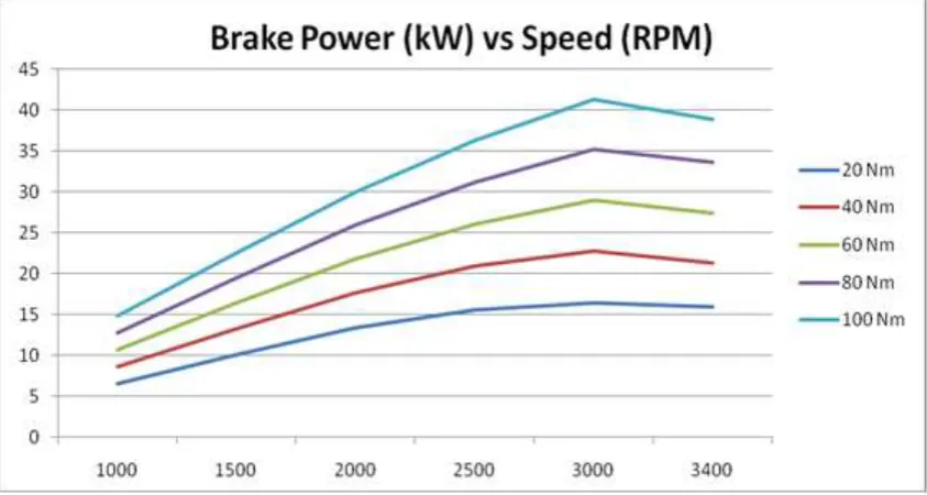
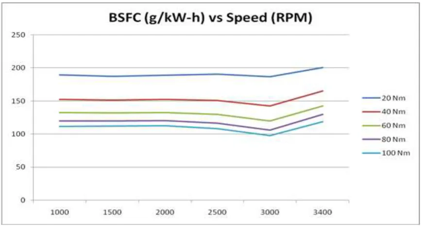
[image:24.595.173.462.329.583.2]From the Mamat et al. (2010) researched, when the brake power achieves maximum point, the brake specific fuel consumption reached it lowest point. Figures 2.3, 2.4, 2.5 and 2.6 shows the different speed effect to the brake power and brake specific fuel consumption (BSFC). The brake power increased when the speed also increased but it decreased after achieved maximum power. The result shows different situation to the BSFC. The BSFC is still maintain when the speed increase until 2500 rpm and then decrease at 3000 rpm but increase after 3000 rpm.
Figure 2.3: The variation in heat carried away by exhaust gases in % with backpressure on engine for different load conditions using exhaust diffuser system
Figure 2.4: Result for varition of backpressure with engine speed (Mohiuddin et al., 2007)
[image:25.595.125.547.403.628.2]Figure 2.6: The different speed effect to brake specific fuel consumption (BSFC) (Mamat et al., 2010)
2.7 Motorcycle engine
Heywood (1988) explained, the purpose of internal combustion engines is the production of mechanical power from the chemical energy contained in the fuel. In internal combustion engine, as distinct from external combustion engines, this energy released by burning or oxidizing the fuel inside the engine. The burning process when the fuel and air mixture together before compress in the engines. The burned products are actual working fluids. The burned product produce high pressure impact to transfer power output directly to the mechanical components in the engine.
2.8 GT Power
Mohiuddin et al. (2007) explained, GT SUITE is an integrated set of computer aided engineering(CAE) tools developed by Gamma Technologies, Ins. for design and analysis of engines, power trains and vehicles. GT SUITE is a complete software to design and simulate the product for analysis. From the Gamma Technologies, these tools are contained in a single executable form which is essential to its use in ‘Intergrated Simulations’. GT SUITE devide to six solvers such as GT Power, GT Drive, GT Vtrain, GT Cool, GT Fuel and GT Crank. In GT SUITE also have GT-ISE is to model-bulding interface and GT-POST is a powerful of supporting tools. Mohiuddin et al. (2007) also say, GT-ISE provides the user with the graphical user interface (GUI) that is used to build models as well as the means to run all GT SUITE applications.
GT Power is industry-standard engine simulation tools, used by all leading engine and vehicle manufacturers and their suppliers. According to F1, NASCAR, IRL, etc all, is also used for ship and power generations engins, small two and four stroke engines and racing engines. GT Power provide for the user with various of components to model any advanced concept. Faisal et al. (2010) studied, GT-Power is a program that widely used in an automotive research area. From the GT Power user manual, among its advantages is its ease of use and its tight integration with the rest of GT SUITE, which give GT Power a virtual engine perspective.
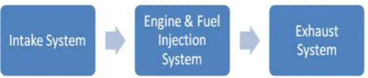
Mohiuddin et al. (2007) have provided some steps for easier model the exhaust system. For the existing exhaust manifold, the pipes are discretized into eight stages for the exhaust manifold. This makes it easier to measure the angle of bend, radius of bend, and the exhaust length. All components are modelled with same specification and dimension with the real components. Figure 2.7 show the basic schematic of engine model in GT Power. From the Faisal et al. (2010) paper, In this GT Power simulation model, the engine will be built into several systems as shown in figure 2.8, there are intake system, engine and fuel injection system and exhaust system.
Figure 2.8: Systems model in the simulation modeling (Faisal et al., 2010)
2.9 Dynamometer
Figure 2.9: Eddy Current Dynanometer (Gitano, 2007)
[image:30.595.115.543.424.663.2]In Malaysia, air pollution and environment protection has drawn much attention. These problems concern since global environmental problem first emerged as a commom wolrdwide concern at the United Nations Conference on Human Environment in 1972. According to Mohsin & Majid (2013) studied, average emission of fine particulate is 77 µ/m3 and this figure is above 50ug/m3 acceptable
standard followed by Department of Environmental for Malaysia.
In the urban city as Kuala Lumpur, the number of motorcycle use rapidly expanded over past several years. Department of Transport Malaysia (2011) stated, the increasing number of motor vehicles is from 19,016782 in 2009 to 2125 milion in 2011. Motorcycle used gasoline fuel for the combustion in the engine. Gasoline fuel produce Carbon Monoxide (CO), Nitrogen Dioxide (NO) and unburned Hydrocarbons (HC) will react with sunlight in the lower atmosphere to form ozone. Figure 2.11 shows relation between exhaust emissions and air/fuel ratio for gasoline engines.
It is estimated that in 2010 the combined air pollutant emission load was 1,681,440 metric tonnes of carbon monoxide (CO); 740,006 metric tonnes of nitrogen dioxides (NO2); 174,820 metric tonnes of sulphur dioxide (SO2) and 26,964
metric tonnes of particulate matter (PM) (Department of Environment Malaysia, 2011). Mohsin & Majid, (2013) stated, in 2010 the emission load of HC and CO was estimated to be 372,924 metric tonnes and 1,597,955 metric tonnes respectively. Except for PM, there was an increase in emission load for HC, CO, SO2 and NO2 as
Figure 2.11: Relation between exhaust emissions and air/fuel ratio for Gasoline Engines (Martyr & Plint, 2007)
Figure 2.12: Estimated annual air pollutant emission loads of HC, CO, PM, NO2 and
[image:32.595.111.505.426.699.2]CHAPTER 3
METHODOLOGY
Figure 3.1: Flowchart for research process Exhaust measurement
Introduction
Literature Review
Methodology
Engine selection
Yes
Result and discussion
Presentation
Finish Submit thesis
Yes
Conclusion Experiment setup
Data analysis
No
Simulation setup
Data analysis No
3.1 Engine selection and exhaust measurement
The selected engine for this study is a motorcycle engine with engine capacity of 125cc. Table 3.1 shows the engine specification of 125cc four stroke motorcycle gasoline engine. Based on Mohd Faisal, Ahmad Jais, Hazlina, & Mohd Taufiq, (2013) research, four stroke spark ignition engine has been selected and are of interest because of they have the potential for very lean operation and they might operate unthrottled (or less throttled) at part load. Mohiuddin, Rahamn, & Dzaidin, (2007) stated, the major area of concern in the work is to focus on the engine of exhaust manifold instead of the whole components of exhaust system.
[image:36.595.128.514.493.770.2]By using GT-Power software, the whole components of exhaust manifold must be considered to insert the parameters in the software for simulation and analysis because the exhaust manifold cannot perform by itself. The simulation and analysis process must have combination of all exhaust components. The components of exhaust system that will be measured are; exhaust manifold, catalytic converter, pipes, and muffler. The exhaust size for 125cc motorcycle engine take from the intake manifold to the end of pipe. Table 3.2 shows the different length of exhaust.
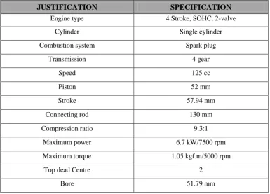
Table 3.1: The specification of 125cc four Stroke Motorcycle Gasoline engine
JUSTIFICATION SPECIFICATION
Engine type 4 Stroke, SOHC, 2-valve
Cylinder Single cylinder
Combustion system Spark plug
Transmission 4 gear
Speed 125 cc
Piston 52 mm
Stroke 57.94 mm
Connecting rod 130 mm
Compression ratio 9.3:1
Maximum power 6.7 kW/7500 rpm
Maximum torque 1.05 kgf.m/5000 rpm
Top dead Centre 2
REFERENCES
Abraham JA. (2010). Fundamentals of Materials Science and Engineering: An
Integrated Fundamentals of Materials Science and Engineering (3rd edition). Inc., 111 River Street, Hoboken, New Jersey.: John Wiley & Sons, Inc.
Ahmet Selamet. (1999). Exhaust System Reduces Auto Emissions, Boosts Engine Performance, ScienceDaily, Ohio State University.
Bagri, S., & Chaube, D. A. (2013). Effect of SC5D Additive on the Performance and Emission \nCharacteristics of CI Engine. International Journal of Modern Engineering Research (IJMER), 3(5), 2831–2835.
Bisen, H. B., & Suple, Y. R. (2013). Experimental Investigations of Exhaust Emissions of four Stroke SI Engine by using direct injection of LPG and its analysis.
International Journal of Modern Engineering Research (IJMER), 3(ISSN: 2249-6645), 1600–1605.
B.P.PUNDIR. (2010). IC Engines : Combustion and Emissions. Oxford, U.K.: Department of Mechanical Engineering, Indian Institute of Technology Kanpur, India.
Department of Environment Malaysia. (2011). A Guide to Air Pollution Index, Kuala Lumpur.
Donaldson, D. (2008). Medium- and Heavy-Duty Exhaust Products Guide. EDonaldson Company, Inc., 9.
Faisal, M., Hushim, B., Jais, A., Alimin, B., Faizal, M., Mohideen, B., Mohd, B. (2010). a Review and Investigation Framework on Port-Fuel Injection for Small 4-Stroke Single Cylinder Engine. In Postgraduate Seminar 2010, Universiti Tun Hussein Onn Malaysia.
Faiz, A., Weaver, C. S., & Walsh, M. P. (1996). Air pollution from motor vehicles. Annals of the New York Academy of Sciences, 136(12), 277–301.
Gitano, H. (2007). Dynamometer Basics, (n.d), University of Science Malaysia, Malaysia.
Han-chi, H., Hong-wu, H., & Yi-jie, B. (2012). Optimization of Intake and Exhaust System for FSAE Car Based on Orthogonal Array Testing. International Journal of Engineering and Technology, 2(3), 392–396.
Heywood, J. B. (1988). Internal Combustion Engine Fundamental, Director, Sloon Automotive laboratory, Massachusetts Institute of Technology.
Hultgren, L. (2011). Full-Scale Turbofan-Engine Turbine Transfer Function
Determination Using Three Internal Sensors. Portland: NASA Glenn Research Center.
Ioannis Gravalos, Dimitrios Moshou, Theodoros Gialamas, Panagiotis Xyradakis, D. K. and Z. T. (2011). Performance and Emission Characteristics of Spark Ignition Engine Fuelled with Ethanol and Methanol Gasoline Blended Fuels. (M. Manzanera, Ed.).
Martyr, A. J., & Plint, M. A. (2007). Engine Testing Theory and Practice. Published by Elsevier Ltd, Jordan Hill, Oxford OX2 8DP.
Mat, S., & Salim, M. A. (2011). Journal of Electrical and Mechanical Engineering The Performance Improvement for Plenum inside Intake Manifold in Automotive Vehicles Engine, 2(1), 13–20.
Mohd Faisal, H., Ahmad Jais, A., Hazlina, S., & Mohd Taufiq, M. (2013). PFI System for Retrofitting Small 4-Stroke Gasoline Engines. International Journal of
Environmental Science and Development, 4(4), 375–378.
Mohiuddin, A. K. M., Rahamn, A., & Dzaidin, M. (2007). Optimal Design Of Automobile Exhaust System Using Gt- Power. International Journal of Mechanical and Materials Engineering (IJMME), 2(1), 40–47.
Mohsin, R., & Majid, Z. A. (2013). Comparative study on exhaust emission and engine performance of single cylinder spark-ignited engine operated on gasoline and natural gas. International Journal of Engineering and Technology, 1, 35–43. Obodeh, O., & Ogbor, a. D. (2009). Improving the performance of two-stroke
motorcycle with tuned adjustable exhaust pipe. Research Journal of Applied Sciences, Engineering and Technology, 1(2), 59–65.
Patil, A. A., Navale, L. G., & Patil, V. S. (2014). Design , Analysis of Flow Characteristics of Exhaust System and Effect of Back Pressure on Engine Performance. International Journal of Engineering , Business and Enterprise Applications ( IJEBEA ), 99–103.
Reddy, M. R., & Reddy, K. M. (2012). Design And Optimization Of Exhaust Muffler In Automobiles. International Journal Of Engineering Research and Applications (IJERA), 2(5), 395–398.
Rynne, E. F. (1994). EngineeringAcoustics:Acoustic Measurements and
Instrumentation. Code 711, 496640 Gate Road, Room 19,San Diego, California 92152-6242,: , ChairNaval Command, Control and Ocean Surveillance Center, RDTE Division.
The-best-performance-exhaust-systems. (2011). http://www.carsdirect.com. Retrieved from 16 Mac 2015
Types of exhaust systems. (2001). http://www.helixsf.com/types/. Retrieved from 16 Mac 2015